Disclosure (#ad): As an Amazon Associate I earn from qualifying purchases.
Set Up the Hardware
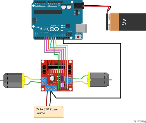
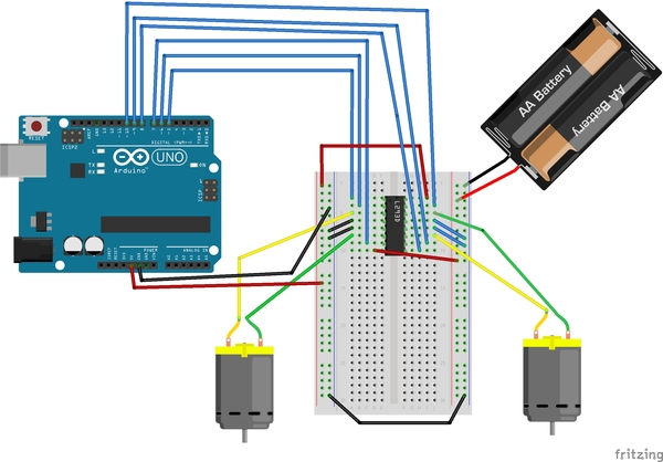
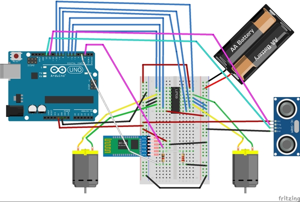
The first thing we need to do is set up the hardware. Below is the wiring diagram, and here is the pdf version so you can see the pin numbers better:
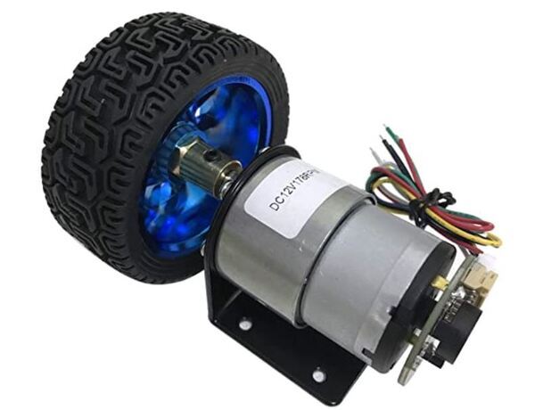
On my motors, the outer pins are the ones that drive the motors. These pins need to be connected to the L298N OUT1-OUT4 pins.
Remove the two black jumpers that are on the board that cover the ENA and ENB pins. Do not remove the other jumper that is near the power input pins.
Write the Code
Now let’s write the code. You will need to:
Load this code to your Arduino from your PC.
Remove the Arduino from your PC.
Turn on your Arduino using the 9V battery.
/*
 * Author: Automatic Addison
 * Website: https://automaticaddison.com
 * Description: Controls the speed and direction of two DC motors.
 */

// Motor A connections
const int enA = 9;
const int in1 = 5;
const int in2 = 6;

// Motor B connections
const int enB = 10;
const int in3 = 7;
const int in4 = 8;

// Set the speed (0 = off and 255 = max speed)
const int motorSpeed = 128;

void setup() {

  // Motor control pins are outputs
  pinMode(enA, OUTPUT);
  pinMode(enB, OUTPUT);
  pinMode(in1, OUTPUT);
  pinMode(in2, OUTPUT);
  pinMode(in3, OUTPUT);
  pinMode(in4, OUTPUT);

  // Turn off motors - Initial state
  digitalWrite(in1, LOW);
  digitalWrite(in2, LOW);
  digitalWrite(in3, LOW);
  digitalWrite(in4, LOW);

  // Set the motor speed
  analogWrite(enA, motorSpeed);
  analogWrite(enB, motorSpeed);
}

void loop() {

  // Go forwards
  go_forward();
  delay(3000);

  // Go backwards
  go_backwards();
  delay(3000);

  // Go right
  go_right();
  delay(3000);

  // Go left
  go_left();
  delay(3000);

  // Stop
  stop_all();
  delay(3000);
}

/*
 *  Forwards, backwards, right, left, stop.
 */
void go_forward() {
  digitalWrite(in1, HIGH);
  digitalWrite(in2, LOW);
  digitalWrite(in3, HIGH);
  digitalWrite(in4, LOW);
}
void go_backwards() {
  digitalWrite(in1, LOW);
  digitalWrite(in2, HIGH);
  digitalWrite(in3, LOW);
  digitalWrite(in4, HIGH);
}
void go_right() {
  digitalWrite(in1, HIGH);
  digitalWrite(in2, LOW);
  digitalWrite(in3, LOW);
  digitalWrite(in4, HIGH);
}
void go_left() {
  digitalWrite(in1, LOW);
  digitalWrite(in2, HIGH);
  digitalWrite(in3, HIGH);
  digitalWrite(in4, LOW);
}
void stop_all() {
  digitalWrite(in1, LOW);
  digitalWrite(in2, LOW);
  digitalWrite(in3, LOW);
  digitalWrite(in4, LOW);
}
Run the Code
When you run this code, you will see your motors move forwards, backwards, right turn, left turn, and then stop. If your motors don’t do this exact sequence, consider switching the position of the wire connections that both motors have to the L298N.
In this tutorial, we’ll learn about the Jacobian matrix, a useful mathematical tool for robotics.
Real-World Applications
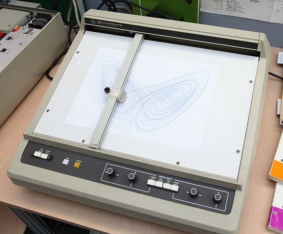
There are some use cases (e.g. robotic painting) where we want to control the velocity of the end effector (i.e. paint sprayer, robotic hand, gripper, etc.) of a robotic arm. One way to do this is to use a library to set the desired speed of each joint on a robotic arm. I did exactly this in this post.
A car painting robot. If the robotic arms move too fast, they will do a poor job painting the vehicle. We can use Jacobian matrices to help control the speed of the arm. Image Source: ResearchGate.
Another way we can do this is to use a mathematical tool called the Jacobian matrix. The Jacobian matrix helps you convert angular velocities of the joints (i.e. joint velocities) into the velocity of the end effector of a robotic arm.
For example, if the servo motors of a robotic arm are rotating at some velocity (e.g. in radians per second), we can use the Jacobian matrix to calculate how fast the end effector of a robotic arm is moving (both linear velocity x, y, z and angular velocity roll ωx, pitch ωy, and yaw ωz).
Prerequisites
It is helpful if you know how to do the following:
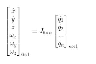
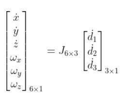
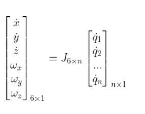
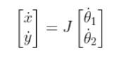
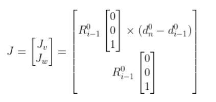
For a robot that operates in three dimensions, the Jacobian matrix transforms joint velocities into end effector velocities using the following equation:
q with the dot on top represents the joint velocities (i.e. how fast the joint is rotating for a revolute joint and how fast the joint is extending or contracting for a prismatic joint) .
The size of this vector is n x 1, with n being equal to the number of joints (i.e. servo motors or linear actuators) in your robotic arm.
Note that q can represent either revolute joints (typically represented as θ) or prismatic joints (which I usually represent as d, which means displacement)
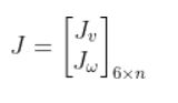
J is the Jacobian matrix. It is an m rows x n column matrix (m=3 for two dimensions, and m=6 for a robot that operates in three dimensions). n represents the number of joints.
The matrix on the left represents the velocities of the end effector.
x, y, and z with the dots on top represent linear velocities (i.e. how fast the end effector is moving in the x, y, and z directions relative to the base frame of a robotic arm)
ωx, ωy, and ωzrepresent the angular velocities (i.e. how fast the end effector is rotating around the x, y, and z axis of the base frame of a robotic arm).
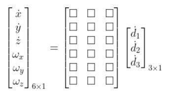
The equation using the Jacobian would be as follows:
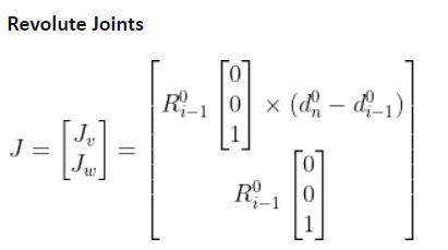
Looking closer at the Jacobian, this term can be divided into two parts, where the first three rows are used for linear velocities, and the bottom three rows are used for angular velocities.
Taking a look at a real-world example, you’ll see that the SCARA robot that I’ve been building (see my YouTube video here) can only rotate around the z axis of the base frame (i.e. straight upwards towards the ceiling out of the board). There is no rotation around the x or y axes of the base frame.
How To Find the Jacobian Matrix for a Robotic Arm
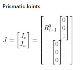
To fill in the Jacobian matrix, we use the following tables:
The upper half of the matrix is used to determine the linear components of the velocity, while the bottom part is used to determine the rotational components of the velocity.
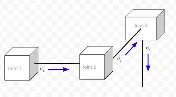
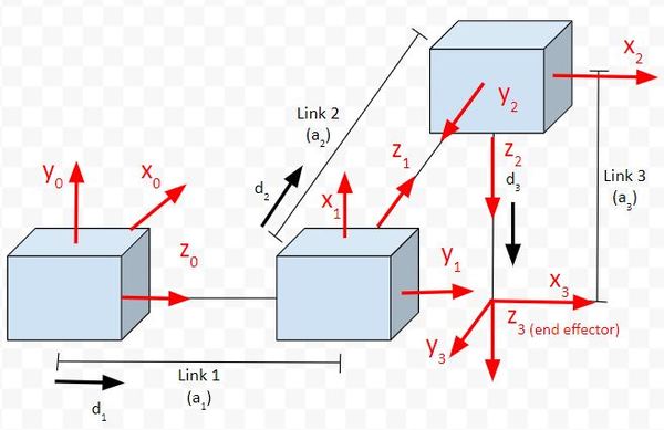
Example 1: Cartesian Robot
Consider the following robot that has three prismatic joints.
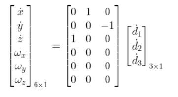
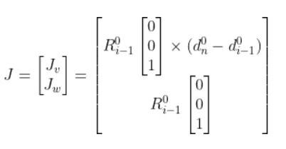
Here is the equation with the Jacobian matrix:
Which is the same as:
Notice that the q’s were replaced with d’s, which represent “displacement” of the prismatic joint (i.e. linear actuator).
To fill in the Jacobian matrix, we have to come one column at a time from left to right. Each column represents a single joint.
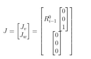
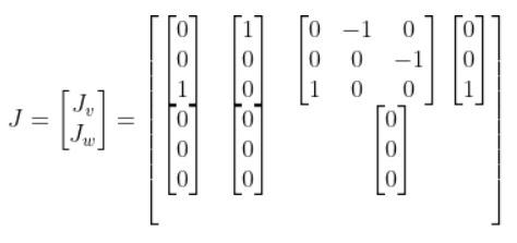
Let’s start with Joint 1. Making i = 1, we get:
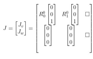
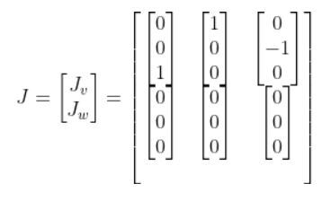
Now let’s fill in the second column of the matrix which represents Joint 2. Making i = 2, we get:
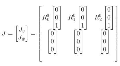
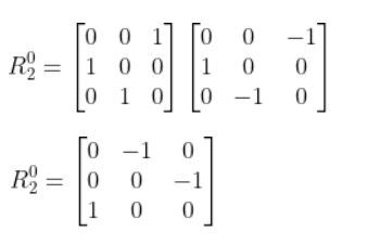
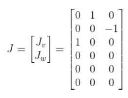
Finally, let’s fill in column 3, which represents Joint 3.
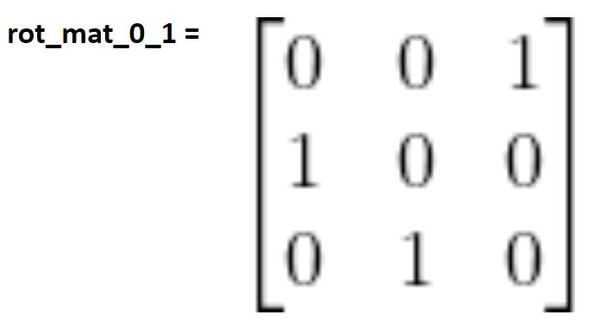
The R in the matrix above stands for “rotation matrix.” For example, R01 stands for the rotation matrix from frame 0 to frame 1.
Now to fill in the rotation matrices, we need to add reference frames to the joints. This tutorial shows you how to do that. I’m going to use that same graphic here.
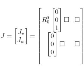
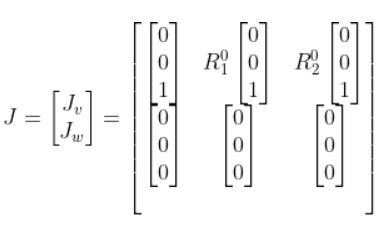
Let’s start with R00. Since we have no rotation from frame to frame 0, R00 is the identity matrix. Anything that is multiplied by the identity matrix will remain itself, so our matrix now looks like this:
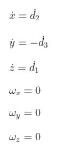
We can do matrix multiplication on the right side of this equation above to yield six equations:
If we look at the kinematic diagram, we can see if the equations above make sense. You can see that the speed of the end effector in the x0 direction is determined by the displacement of joint 2 (i.e. d2).
You can see that the speed of the end effector in the y0 direction is determined by the negative displacement of joint 3 (i.e. d3).
The speed of the end effector in the z0 direction is determined by the positive displacement of joint 1 (i.e. d1).
The last three equations tell us that the end effector will never be able to rotate around the x, y, and z axes of frame 0, the base frame of the robot. This makes sense because all of the joints are prismatic joints. We would need to have revolute joints in order to get rotation.
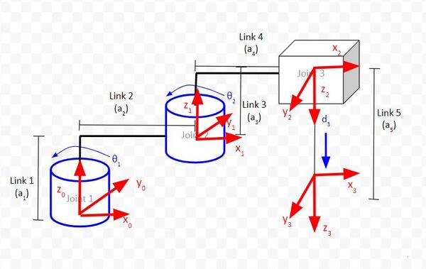
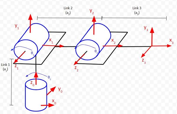
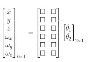
Example 2: Articulated Robot
Now let’s take a look at another example, an articulated robot that has the following kinematic diagram.
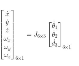
This robotic arm will have three columns since it has three joints (i.e. servo motors). As usual, it will have six rows since we’re working in three dimensions.
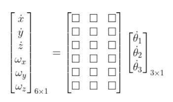
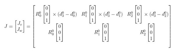
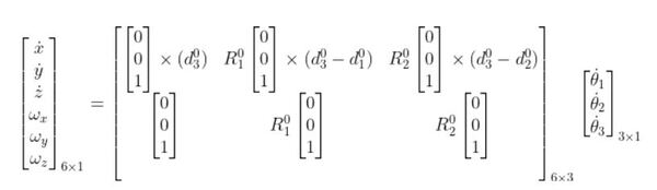
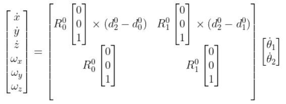
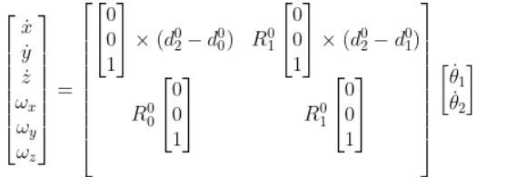
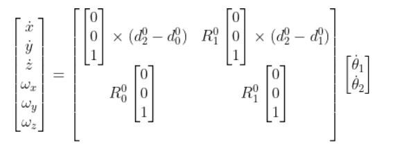
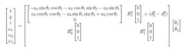
Our equation that relates joint velocity to the velocity of the end effector takes the following form:
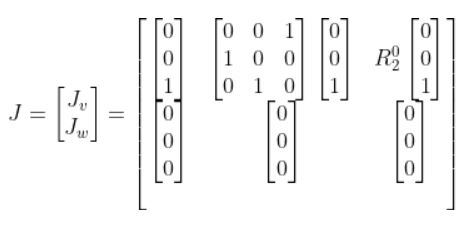
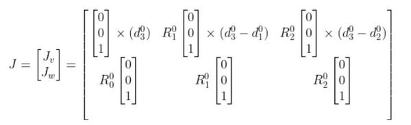
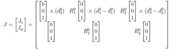
The Jacobian matrix J (the 6×3 matrix above with the squares) takes the following form since we have all revolute joints:
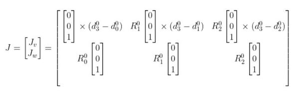
So using the form above, our Jacobian matrix for the articulated robotic arm is (n is the number of joints):
You’ll see that each column (i = 1, 2, and 3) uses the Jacobian for revolute joints since each joint is a revolute joint.
The x in the above matrix stands for the cross product.
Now, let’s fill in this Jacobian matrix, going one column at a time from left to right.
R00 is the identity matrix since there is no rotation from frame 0 to itself.
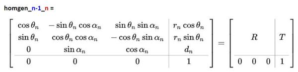
We now need to find d03. d03 comes from the upper right of the homogeneous transformation matrix from frame 0 to frame 3 (i.e. homgen_0_3). That is, it comes from the T part of the matrix of the following form:
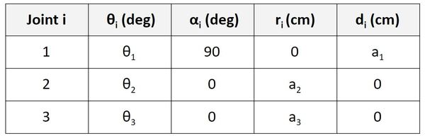
To get the homogeneous transformation matrix from frame 0 to frame 3, we first have to fill in the Denavit-Hartenberg table for the articulated robotic arm. I show you how to do this in this tutorial.
Here was the table we got:
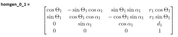
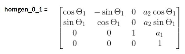
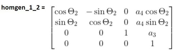
Now, we take a look at that table and go one row at a time, starting with the Joint 1 row. To find the homogeneous transformation matrix from frame 0 to frame 1, we use the values from the first row of the table to fill in this…
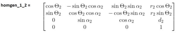
We then look at the second row of the D-H table and fill in the homogeneous transformation matrix from frame 1 to 2…
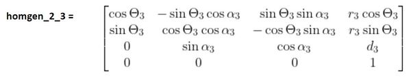
We then look at the third row of the D-H parameter table to fill in the homogeneous transformation matrix from frame 2 to 3…
Then, to find the homogeneous transformation matrix from the base frame (frame 0) to the end-effector frame (frame 3), we would multiply those three transformation matrices together.
homgen_0_3 = (homgen_0_1)(homgen_1_2)(homgen_2_3)
d03 is a three element vector that is made up of the values of the first three rows of the rightmost column of homgen_0_3. I won’t go through all the matrix multiplication for finding homgen_0_3, but if you follow the method I’ve described above, you will be able to get it.
d00 will always be 0, so our Jacobian will look like this at this stage:
Going to the second column of the matrix, d01 is a three element vector that is made up of the values of the first three rows of the rightmost column of homgen_0_1 (which you found earlier).
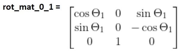
R01 is below (see this tutorial for how to find it):
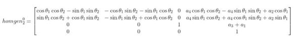
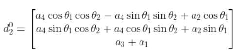
Going to the third column, d02 is a three element vector that is made up of the values of the first three rows of the rightmost column of homgen_0_2. Since you know homgen_0_1 and homgen_1_2, you can multiply those two matrices together to get homgen_0_2.
homgen_0_2 = (homgen_0_1)(homgen_1_2)
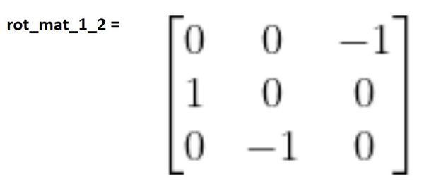
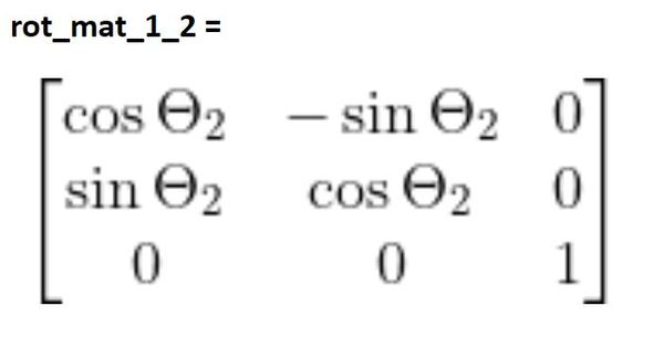
R02 (i.e. rot_mat_0_2) is found by multiplying the rotation matrices from frame 0 to frame 1 and from frame 1 to frame 2.
rot_mat_0_2 = (rot_mat_0_1)(rot_mat_1_2)
We know rot_mat_0_1. Rot_mat_1_2 is the following:
Now in the top half your Jacobian matrix you will need to go column by column and take the cross product of two three-element vectors.
In a real-world setting, you would use a Python library like NumPy to perform this operation. If you do a search for “numpy.cross” you will see how to do this. For example, here is some Python code of how to take the cross product of two three-element vectors:
x = [1, 2, 3]
y = [4, 5, 6]
np.cross(x, y)
Output:
array([-3,  6, -3])
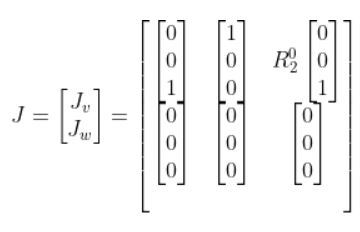
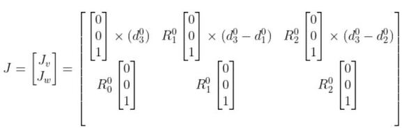
Now going to the bottom half of the matrix, R00 is the identity matrix.
You can fill in the rest of the bottom half of the Jacobian matrix because we know R01 and R02.
Once you have the Jacobian, you will then have the following setup:
From the setup above, you can find six equations, one for each velocity variable (on the far left). These equations enable us to calculate the velocities of the end effector of the articulated robotic arm given the joint velocities.
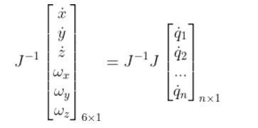
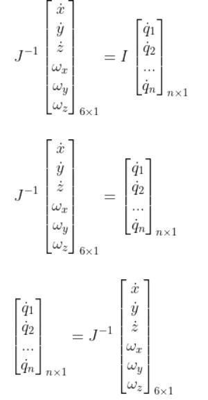
Inverse Jacobian Matrix
In the previous section, we looked at how to calculate the velocities of the end effector of a robotic arm given the joint velocities. What if we want to do the reverse? We want to calculate the joint velocities given desired velocities of the end effector?
To solve this problem, we must use the inverse of the Jacobian matrix.
A matrix multiplied by its inverse is the identity matrix I. The identity matrix is the matrix version of the number 1.
You can only take the inverse of a square matrix. A square matrix is a matrix where the number of rows is equal to the number of columns.
So how would we find J-1? Let’s take a look at an example.
Example
Suppose we have the following two degrees of freedom robotic arm.
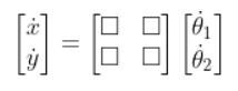
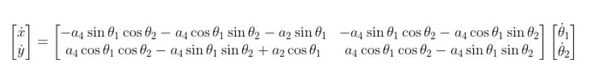
We have the following equation where the matrix with the 12 squares is J, the Jacobian matrix.
We only have two servo motors. These two servo motors control the velocity of the end effector in only the x and y directions (e.g. we have no motion in the z direction).
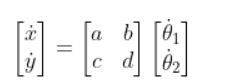
Suppose the only thing that matters to us is the linear velocity in the x direction and the linear velocity in the y direction. We can simplify our equation accordingly to this, where the matrix with the squares is J:
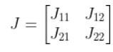
Let’s replace those squares with some variables.
Since…
To get the J-1, we use the following formula:
To get J-1, we first need to find J. J has two revolute joints. Revolute joints take the following form:
So the equation for our two degree of freedom robotic arm will look like this:
R00 is the identity matrix.
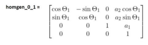
To calculate d02 , we need to find the homogeneous transformation matrix from frame 0 to frame 2. We did exactly this on this tutorial.
homgen_0_2 = (homgen_0_1)(homgen_1_2)
When you do this multiplication, you get the following:
Based on the homogeneous matrix above, here is d02.
Plugging that into this expression below and performing the cross product with the vector [0 0 1], we get:
And since:
We know that:
R01 is the 3×3 matrix in the upper left of homgen_0_1.
d01 is the 3×1 vector in the upper right of homgen_0_1.
We already know d02. We found that earlier in this tutorial.
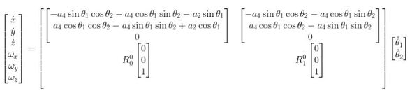
We can therefore fill in the rest of the upper half of the Jacobian matrix to get this:
J is that big matrix above. Since we are only concerned about the linear velocities in the x and y directions, this:
Becomes…
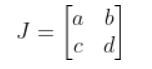
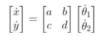
J is that big matrix above. It takes the form:
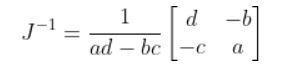
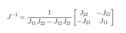
To get the inverse of J (i.e. J-1), we do the following:
The (J11J22 – J12J21) in the denominator is known as the determinant. I’ll call 1/(J11J22 – J12J21) the reciprocal of the determinant.
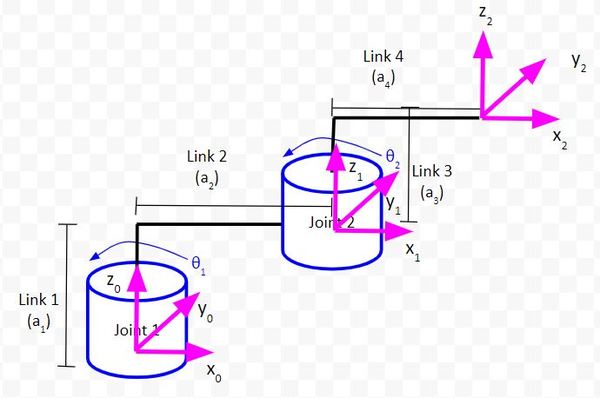
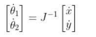
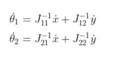
Once we know J-1, we can use the following expression to solve the joint velocities given the velocities of the end effector in the x and y directions.
Which is the same as:
Which is:
Programming the Jacobian on a Real Robot
Let’s take a look at all this math we’ve done so far by implementing it on a real-world robot.
To do this section, you need to have assembled the two degrees of freedom SCARA robot here.
We want to calculate the rotation velocity of the two joints (i.e. servo motors) based on desired linear velocities of the end effector.
We will program our robotic arm so that the end effector of the robotic arm moves in a straight line at a constant linear velocity.
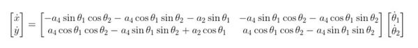
This equation will come in handy. That big nasty matrix below is the Jacobian. We’ll use it to calculate the inverse Jacobian matrix in our code.
Open the Arduino IDE and create a new sketch named jacobian_based_path_planning_v2.ino.
Write the following code. It is helpful to write the code line by line rather than copying and pasting so that you understand what is going on.
/*
Program: Jacobian-Based Path Planning
File: jacobian_based_path_planning_v1.ino
Description: This program moves the end effector of a SCARA robotic arm based on your
desired x and y linear velocities.
Motion is calculated using the Jacobian matrix which relates joint velocities
to end effector velocities.
Note that Servo 0 = Joint 1 and Servo 1 = Joint 2.
Author: Addison Sears-Collins
Website: https://automaticaddison.com
Date: October 14, 2020
*/
#include <VarSpeedServo.h>
// Define the number of servos
#define SERVOS 2
// Conversion factor from degrees to radians
#define DEG_TO_RAD 0.017453292519943295769236907684886
// Conversion factor from radians to degrees
#define RAD_TO_DEG 57.295779513082320876798154814105
// Create the servo objects.
VarSpeedServo myservo[SERVOS];
// Speed of the servo motors
// Speed=1: Slowest
// Speed=255: Fastest.
const int default_speed = 255;
const int std_delay = 10; // Delay in milliseconds
// Attach servos to digital pins on the Arduino
int servo_pins[SERVOS] = {3,5};
// Angle of the first servo
float theta_1 = 0;
float theta_1_increment = 0;
float theta_1_dot = 0; // rotational velocity of the first servo
// Angle of the second servo
float theta_2 = 0;
float theta_2_increment = 0;
float theta_2_dot = 0; // rotational velocity of the second servo
// Linear velocities of the end effector relative to the base frame
// Units are in centimeters per second
// If x_dot = 0.0, the end effector will move parallel to the y axis
// Play around with these numbers, and observe the motion of the end effector
// relative to the x and y axes of the base frame of the robotic arm.
float x_dot = 0.0;
float y_dot = 1.0;
// Jacobian variables
float reciprocal_of_the_determinant;
float J11;
float J12;
float J21;
float J22;
// Inverse Jacobian variables
float J11_inv;
float J12_inv;
float J21_inv;
float J22_inv;
// Link lengths in centimeters
// You measure these values using a ruler and the kinematic diagram
float a2 = 5.9;
float a4 = 6.0;
void setup() {
Serial.begin(9600);
// Attach the servos to the servo object
// attach(pin, min, max ) - Attaches to a pin
// setting min and max values in microseconds
// default min is 544, max is 2400
// Alter these numbers until both servos have a
// 180 degree range.
myservo[0].attach(servo_pins[0], 544, 2475);
myservo[1].attach(servo_pins[1], 500, 2475);
// Set the angle of the first servo.
theta_1 = 0.0;
// Set the angle of the second servo.
theta_2 = 90.0;
// Set initial servo positions
myservo[0].write(theta_1, default_speed, true);
myservo[1].write(theta_2, default_speed, true);
// Let servos get into position
delay(3000);
}
void loop() {
// Make sure the servos stay within their 180 degree range
while (theta_1 <= 180.0 && theta_1 >= 0.0 && theta_2 <= 180.0 && theta_2 >= 0.0) {
// Convert from degrees to radians
theta_1 = theta_1 * DEG_TO_RAD;
theta_2 = theta_2 * DEG_TO_RAD;
// Calculate the values of the Jacobian matrix
J11 = -a4 * sin(theta_1) * cos(theta_2) - a4 * cos(theta_1) * sin(theta_2) - a2 * sin(theta_1);
J12 = -a4 * sin(theta_1) * cos(theta_2) - a4 * cos(theta_1) * sin(theta_2);
J21 = a4 * cos(theta_1) * cos(theta_2) - a4 * sin(theta_1) * sin(theta_2) + a2 * cos(theta_1);
J22 = a4 * cos(theta_1) * cos(theta_2) - a4 * sin(theta_1) * sin(theta_2);
reciprocal_of_the_determinant = 1.0/((J11 * J22) - (J12 * J21));
// Calculate the values of the inverse Jacobian matrix
J11_inv = reciprocal_of_the_determinant * (J22);
J12_inv = reciprocal_of_the_determinant * (-J12);
J21_inv = reciprocal_of_the_determinant * (-J21);
J22_inv = reciprocal_of_the_determinant * (J11);
// Set the rotational velocity of the first servo
theta_1_dot = J11_inv * x_dot + J12_inv * y_dot;
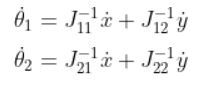
// Set the rotational velocity of the second servo
theta_2_dot = J21_inv * x_dot + J22_inv * y_dot;
// Convert rotational velocity in radians per second to X radians in std_delay milliseconds
// Note that 1 second = 1000 milliseconds and each delay is std_delay milliseconds
theta_1_increment = (theta_1_dot) * (1/1000.0) * std_delay;
// Convert rotational velocity in radians per second to X radians in std_delay milliseconds
// Note that 1 second = 1000 milliseconds and each delay is std_delay milliseconds
theta_2_increment = (theta_2_dot) * (1/1000.0) * std_delay;
theta_1 = theta_1 + theta_1_increment;
theta_2 = theta_2 + theta_2_increment;
// Convert the new angles from radians to degrees
theta_1 = theta_1 * RAD_TO_DEG;
theta_2 = theta_2 * RAD_TO_DEG;
Serial.println(theta_1);
Serial.println(theta_2);
Serial.println(" ");
myservo[0].write(theta_1, default_speed, true);
myservo[1].write(theta_2, default_speed, true);
delay(std_delay); // Delay in milliseconds
}
}
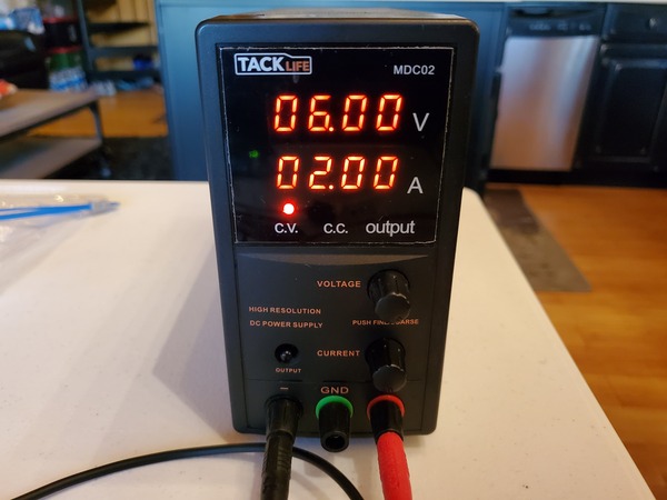
Set the voltage limit on your DC power supply to 6V and the current limit to 2A.
Run the code. You should see the end effector of your robotic arm move parallel to the y axis in a straight line because we set:
After a few seconds, the robotic arm will stop moving in a straight line. The reason for this is that the robotic arm can only move a fixed distance in the positive y direction due to the lengths of the links. The servos, however, continue to rotate until either the first servo or the second servo (or both) reach the limit of their range of rotation (i.e. 0 to 180 degrees).
That’s it! Keep building!
References
Sodemann, Dr. Angela 2020, RoboGrok, accessed 14 October 2020, <http://robogrok.com/>
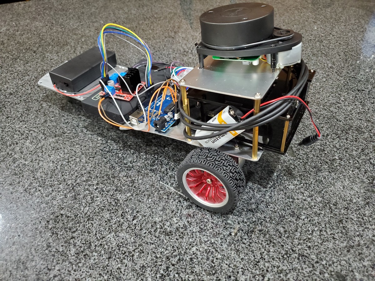
In this tutorial, we will build an autonomous, obstacle-avoiding wheeled robot from scratch using ROS (Robot Operating System), the popular robotics development platform. I decided to write this tutorial because a lot of introductory books and tutorials on ROS, including the official ROS tutorials, have you learn ROS by working with robots in simulation; but you never learn how to apply what you have learned to an actual physical robot that senses, thinks, and acts in the real world.
Our goal is to build the cheapest, most complete robot we could possibly build using ROS.
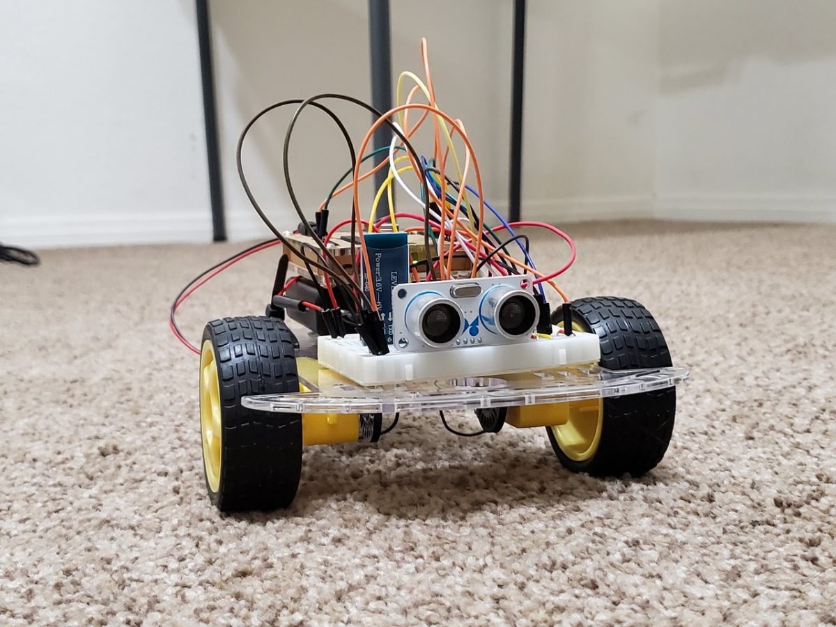
We will use low-cost components to build the robot “body” (I don’t want to spend hundreds of dollars for a robot kit).
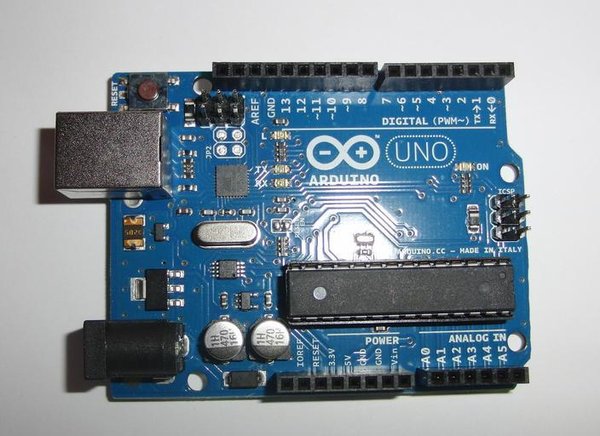
The “brain” of the robot will be Arduino. Arduino is a popular microcontroller (think of it as a small computer) for building electronics projects.
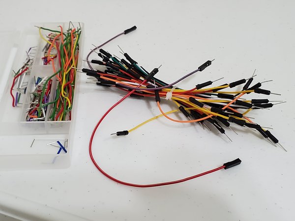
The robot’s “nervous system” — the communication lines that enable the brain to transmit signals and sensory information to and from different parts of its body — will be some inexpensive jumper wires and small electronic components.
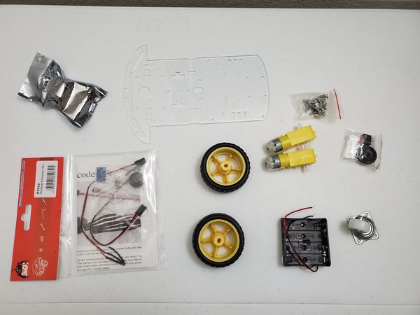
All of the parts you need are listed below in the “You Will Need” section.
There are a lot of steps in this tutorial. Have fun, be patient, and be persistent. Don’t give up! If something doesn’t work the first time around (as is normally the case in robotics), try again. You will learn a lot more by fighting through to the end of this project. Stay relentless!
By the end of this tutorial, you will have rock-solid confidence and will know how to use ROS to design and develop a robot that moves around in the real world (not just on your computer screen).
Real-World Applications
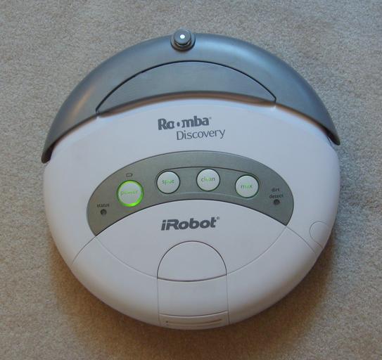
Most models of the Roomba autonomous robotic vacuum cleaner use basic obstacle avoidance techniques (like the one we’ll implement in this project) to clean rooms.
I’m running my Ubuntu Linux inside a virtual machine on Windows 10. If you have MacOS or Linux, that will work just fine. Just make sure you have ROS installed.
If you have experience building a basic wheeled robot using either Arduino or Raspberry Pi, you will find this tutorial easier to follow. If you don’t have that experience, don’t worry. I’ll explain everything as we go.
Also, if you did the Hello World ROS project (to create a basic ROS Publisher and Subscriber node), you will find this tutorial easier to follow.
HC-SR05 Ultrasonic Sensor (HC-SR04 works as well, but it is slightly less accurate. These are the robot’s “eyes”.)
Robot’s Brain
Arduino Uno (Elegoo Uno works just fine and is cheaper than the regular Arduino)
Robot’s Nervous System
400-point Solderless Breadboard (This is the robot’s “spinal cord”…the link between the brain and the nerves in the rest of the body.)
Male-to-Male Jumper Wires (These are the robot’s “nerves” that transmit sensory information and signals to make the robot do stuff like move its motors).
Contains two H-bridges. An H-bridge is a circuit that enables a motor to go both forwards AND backwards.
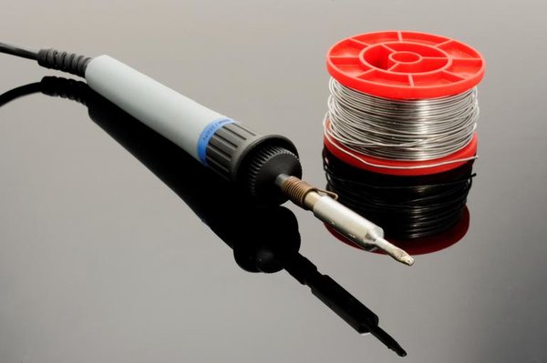
Soldering Equipment
Soldering is a fundamental skill in robotics. It is the process of joining two metal wires or surfaces together using heat, with the use of metal called “solder”.
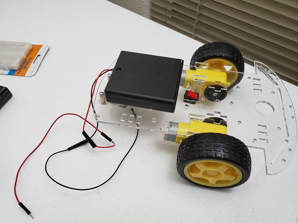
First, open up your robot car chassis kit. You won’t be needing the little switch or the 4 x 1.5V AA battery pack that comes with the robot car chassis, so you can set that aside.
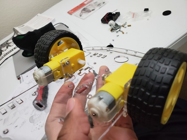
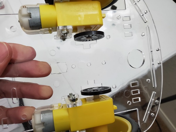
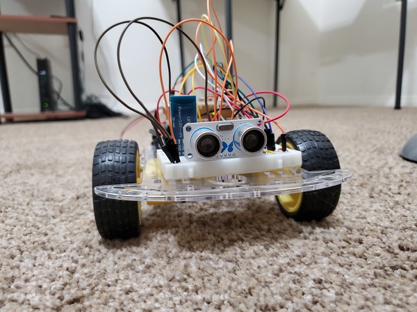
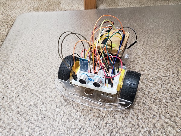
Follow this video below to assemble the robot’s frame:
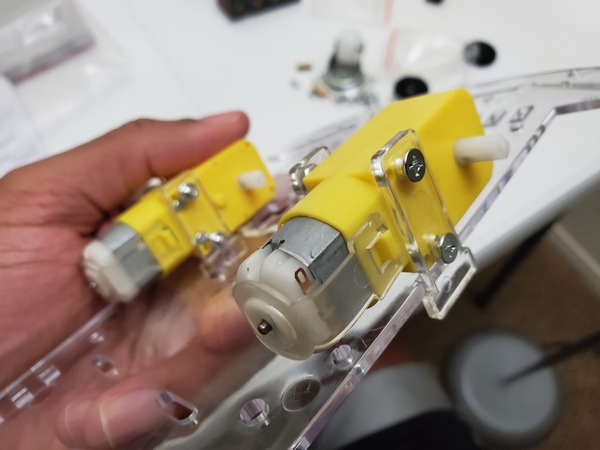
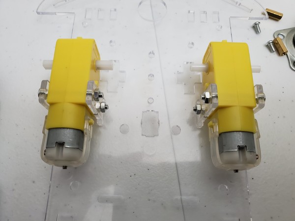
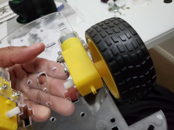
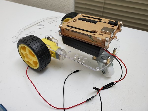
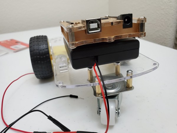
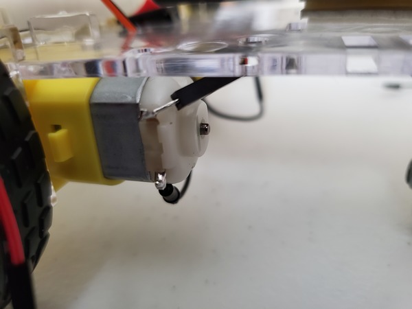
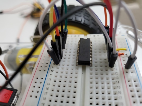
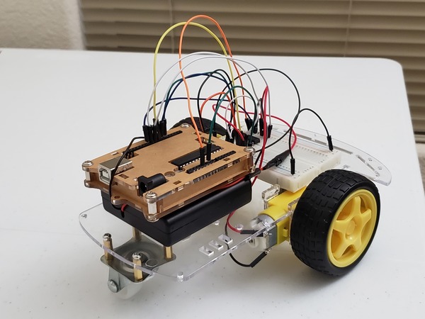
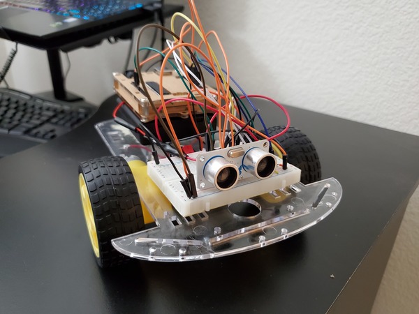
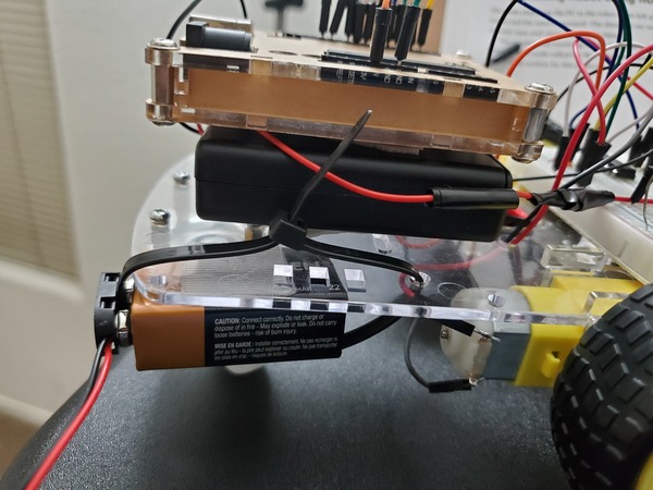
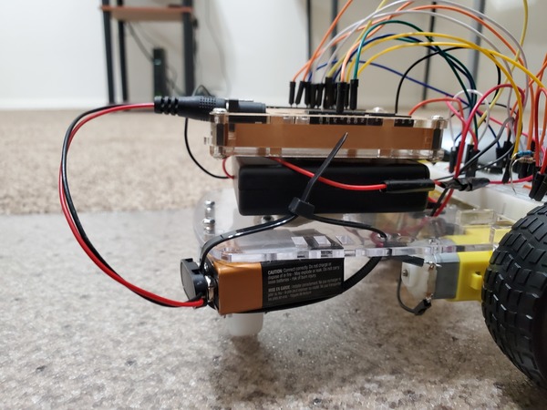
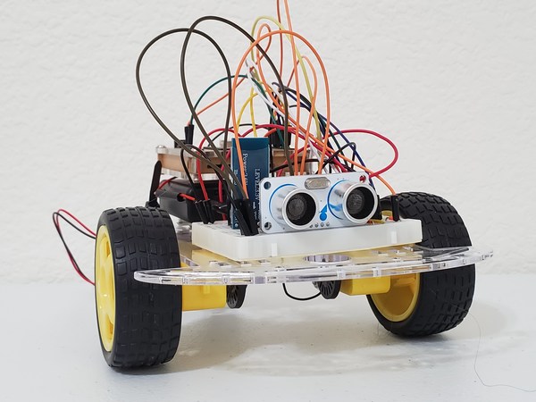
Below are some photos of the assembly of the frame of my robot:
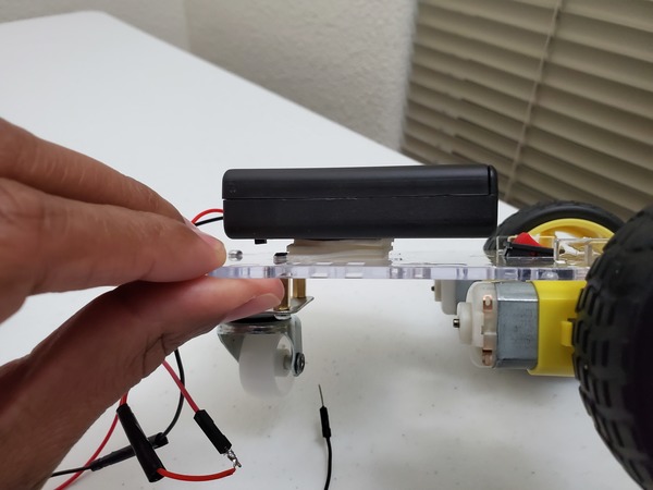
Once you have assembled the robot’s frame, mount the 4 x 1.5V AA battery holder with switch (the one that you purchased) to the rear of the robot. The rear of the robot is the end with the single roller wheel. We will secure it with a few layers of Scotch permanent mounting tape.
Since the leads of the 4×1.5V AA battery pack are kind of short, you can extend the length of them by wrapping each lead with a male-to-male jumper wire. If you know how to solder wires together (just YouTube “How to Solder Wires Together” for some great video tutorials), you can solder these jumper wires to your battery pack leads.
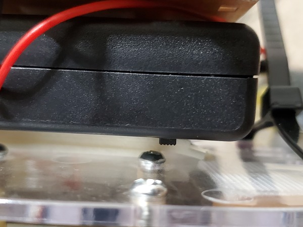
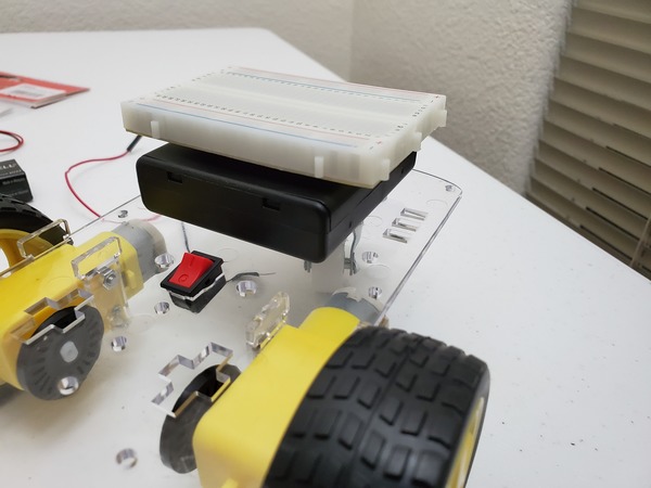
On-Off Switch of the 4×1.5V AA Battery Pack
See how I have extended the lead wires on my battery pack by using male-to-male jumper wires
Mount the Arduino (mine is inside a protective case) to the top of the battery pack using Scotch permanent mounting tape or Velcro fasteners.
Mount the 400-point solderless breadboard to the front of the robot. The back of the solderless breadboard has peel-off tape, but I prefer to use Velcro fasteners so that I can remove the solderless breadboard whenever I want to.
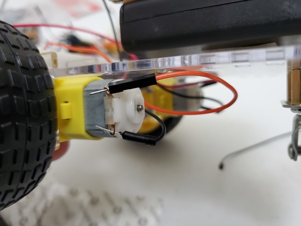
The next thing to do is to connect two male-to-male jumper wires to one of the motors. One jumper wire will thread through the metallic hole on one side of the motor, and the other jumper wire will thread through the hole on the other end of that same motor.
Now wire up the other motor the same way. Connect a male-to-male jumper wire to one of the metallic holes on that motor. Thread another wire through the metallic hole on the other side.
To make sure the jumper wires stick to the metal leads, I recommend you solder them to the leads. Soldering means joining the wire with the metal surface of the motor using hot metal.
Soldering sounds complicated if you have never done it before. It might even seem scary working with hot metal. Don’t worry. I felt the same way before I did my first soldering job. Once you have done one though, you will realize that it is a quick process (lasts no more than a few seconds).
If you have never soldered before, you can check out this video tutorial:
You can also check out my video below where I solder some metal pins to an electronic board. All the soldering equipment used in this video below is listed in the “You Will Need” section earlier in this tutorial:
Now that the robot has its brain (Arduino mounted on the back of the robot) and a body, it needs a “nervous system,” communication lines that enable the brain to transmit signals to and from different parts of its body. In the context of this project, those communication lines are the wires that we need to connect between the different parts of the robot we’re building.
Connect the L293D to the Solderless Breadboard
First, we need to connect the L293D motor controller. The job of this component is to control both of your motors. You can think of an L293D motor controller as “air traffic control” for moving electrons.
In order for a motor to move (or for a light bulb to light…heck any object which needs moving electrons (i.e. electricity) to operate), it needs electrons to flow through it. If we move electrons through a motor in one direction, a motor will spin in one direction. If we reverse the direction electrons travel through a motor, we can make a motor spin the other direction. How can we make electrons change directions? That is the function of the L293D motor controller.
By sending electrons to different combinations of pins of the L293D motor controller, we can make the robot car’s motors go forwards and reverse. You don’t need to know the details of how all this works, but just on a high level know that an L293D motor controller accepts electric signals (i.e. moving electrons) from your Arduino board as well as your batteries (think of batteries and your Arduino as “electron pumps”) and gets them to your motors in a way that causes them to spin either clockwise or counter-clockwise to make the wheels turn.
If you want to deep dive into how H-bridges like the L293D motor controller work, check out this article on Wikipedia.
If you want to understand how electricity (moving electrons) works. Check out this video, which covers the basics.
Ok, with that little bit of theory out of the way, let’s start building again.
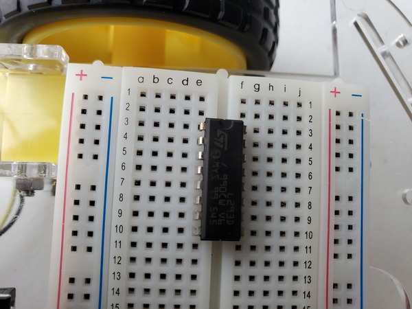
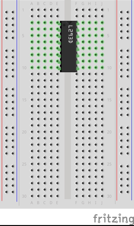
Sink the 16 pins of the L293D motor controller down into the holes of the solderless breadboard so that the controller straddles the gap that runs the length of the breadboard. If this is the first time you have used a solderless breadboard, check out a quick tutorial on how to read a solderless breadboard. There are a lot of good tutorials on YouTube. Here is one I like:
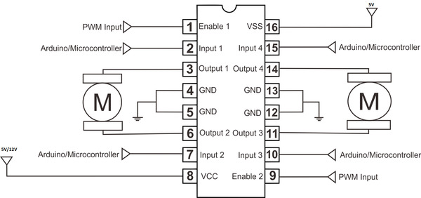
Here is the diagram of the L293D.
Put pin 1 (the pin just to the left of the half-circle notch in the L293D) into pin e3 of the solderless breadboard. You’ll have to bend the legs a bit on the L293D to get it to sink down all the way.
With the L293D settled down firmly into your solderless breadboard, let’s hook everything up. We are going to go from top to bottom on one side of the L293D, and then we will go from top to bottom on the other side of the L293D. We will connect all 16 legs of the L293D, one step at a time, starting from Pin 1.
There are a lot of connections, and you need to get all of them correct in order to get the motors going, so proceed slowly and carefully to make sure you get everything right. No need to hurry.
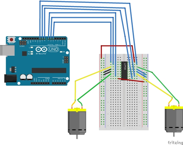
Here is the Arduino with its numbered pins.
Here is L293D.
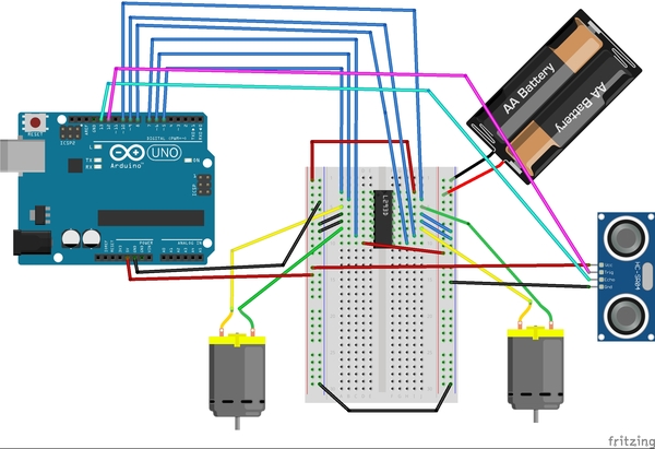
And here is the diagram of all the connections we are about to make (sorry the image is so small…just follow the connections I’ve written below):
Connect Side 1 (Left Motor) of the L293D
Connect Pin 1 of the L293D to Pin 5 of the Arduino.
Pin 1 is the Enable pin of the L293D. It is like a switch that turns the motor ON.
Pin 1 doesn’t make the motor move directly…it just turns the motor on that side to ON so that it is able to move when it receives signals from pins 3 and 6.)
Connect Pin 2 of the L293D to Pin 6 of the Arduino.
Pin 6 on the L293D receives an input signal from the Arduino board, either HIGH (5 volts) or LOW (0 volts) voltage.
Connect Pin 3 of the L293D to one of the leads of Motor A (doesn’t matter which motor, just keep track which one is A and which one is B)
Pin 3 of the L293D outputs a signal to Motor A to make it move.
Connect Pin 4 of the L293D to the blue Ground power rail of your solderless breadboard (the one labeled with a negative (-) sign).
Pin 4 is connected to electric ground (to make sure that the electric charge in the L293D has somewhere to go and dissipate).
Connect Pin 5 of the L293D to the blue Ground power rail of your solderless breadboard (the one labeled with a negative (-) sign).
Pin 5 is connected to electric ground (to make sure that the electric charge in the L293D has somewhere to go and dissipate).
Connect Pin 6 of the L293D to one of the leads of Motor A.
Pin 6 of the L293D outputs a signal to Motor A to make it move.
Connect Pin 7 of the L293D to Pin 7 of the Arduino.
Pin 7 receives an input signal from the Arduino board, either HIGH (5 volts) or LOW (0 volts) voltage.
Connect Pin 8 of the L293D to the red Positive power rail of your solderless breadboard (the one labeled with a positive (+) sign).
This pin requires at least a 5V input power supply (which will come from your batteries…more on this later) to power the motors.
Connect Side 2 (Right Motor) of the L293D
Connect Pin 16 of the L293D to the positive (red) power rail of the breadboard. Then connect the positive (red) power rail to the 5V pin of the Arduino.
This pin is the 5V power supply for the L293D itself. It is not the power supply used to power your motors.
Connect Pin 15 of the L293D to Pin 10 of the Arduino.
Connect Pin 14 of the L293D to one of the leads of Motor B
Connect Pin 13 of the L293D to the blue Ground power rail of your solderless breadboard (the one labeled with a negative (-) sign).
Connect Pin 12 of the L293D to the blue Ground power rail of your solderless breadboard (the one labeled with a negative (-) sign).
Connect Pin 11 of the L293D to one of the leads of Motor B.
Connect Pin 10 of the L293D to Pin 9 of the Arduino.
Connect Pin 9 of the L293D to Pin 8 of the Arduino.
Connect the Power Rails
Now we need to connect the power rails of your breadboard.
Get a jumper wire and connect both blue Ground negative (-) rails together.
Connect the black (negative) lead of the 4×1.5V AA battery pack to the blue Ground rail (note there are two AA batteries in the image…you will need 4).
Connect the red (positive) lead of the battery pack to the red positive power rail of the solderless breadboard.
Connect the blue Ground (negative) rail to the GND pin on the Arduino.
Connect the 5V pin of the Arduino to the red (positive) rail of the solderless breadboard.
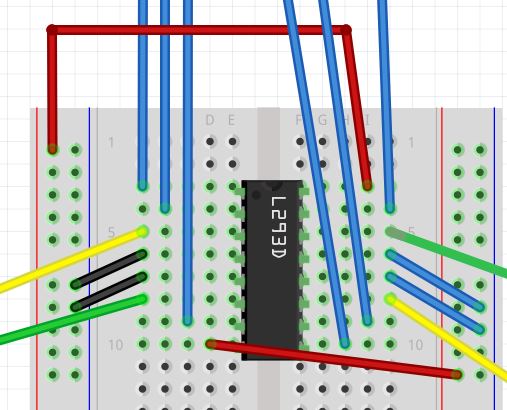
Here is what the final connection should look like:
Test Your Connections
Now let’s test our connections.
Plug in your Arduino to the USB port on your PC.
Open up the Arduino IDE.
We are going to write a program that makes the wheels of your robot go forward, backwards, and then stop. Open a new sketch, and type the following code:
/**
* Bruno Santos, 2013
* feiticeir0@whatgeek.com.pt
* Small code to test DC motors
* 2x with a L298 Dual H-Bridge Motor Driver
* Free to share
**/

//Testing the DC Motors with
// L293D

//Define Pins
//Motor A
int enableA = 5;
int MotorA1 = 6;
int MotorA2 = 7;

//Motor B
int enableB = 8;
int MotorB1 = 9;
int MotorB2 = 10;

void setup() {

  Serial.begin (9600);
  //configure pin modes
  pinMode (enableA, OUTPUT);
  pinMode (MotorA1, OUTPUT);
  pinMode (MotorA2, OUTPUT);

  pinMode (enableB, OUTPUT);
  pinMode (MotorB1, OUTPUT);
  pinMode (MotorB2, OUTPUT);

}

void loop() {
  //enabling motor A and B
  Serial.println ("Enabling Motors");
  digitalWrite (enableA, HIGH);
  digitalWrite (enableB, HIGH);
  delay (3000);
  //do something

  Serial.println ("Motion Forward");
  digitalWrite (MotorA1, LOW);
  digitalWrite (MotorA2, HIGH);

  digitalWrite (MotorB1, LOW);
  digitalWrite (MotorB2, HIGH);

  //3s forward
  delay (3000);

  Serial.println ("Motion Backwards");
  //reverse
  digitalWrite (MotorA1,HIGH);
  digitalWrite (MotorA2,LOW);

  digitalWrite (MotorB1,HIGH);
  digitalWrite (MotorB2,LOW);

  //3s backwards
  delay (3000);

  Serial.println ("Stoping motors");
  //stop
  digitalWrite (enableA, LOW);
  digitalWrite (enableB, LOW);
  delay (3000);
}
Before you upload your code to your Arduino, hold your robot in your hand because the wheels are about to move, and you don’t want your robot to rip away from your computer!
You can now upload the code to your Arduino, and turn the 4×1.5V AA battery pack to the ON position.
When you have had enough, upload a blank, new sketch to your Arduino board (this will stop the program).
Right after you upload the code to your board, the first movement your wheels should make is forward. If a wheel is not moving forward on that first segment of the loop, you need to switch the holes that the two leads from that wheel are connected to. In this case, if it is motor A that is not moving like it should, the leads connected to Pin 3 and Pin 6 of the L293D need to switch places.
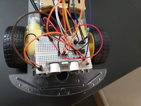
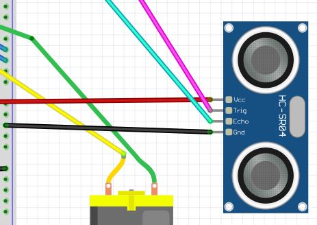
Connect the HC-SR05 Ultrasonic Sensor (the “Eyes”)
Now we need to connect the HC-SR05 ultrasonic sensor to the solderless breadboard in order to be able to detect obstacles in the robot’s path. I recommend you sink the ultrasonic sensor down into available holes of your solderless breadboard. You want the ultrasonic sensor to face the front of your robot.
Here are the connections:
VCC on the sensor connects to the positive (red) rail of the solderless breadboard, which is connected to the 5V pin on the Arduino
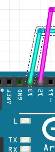
Echo on the sensor connects to Digital Pin 13 on the Arduino
Trig (stands for trigger) on the sensor connects to Digital Pin 12 on the Arduino
GND (stands for Ground) on the sensor connects to ground on the solderless breadboard (blue negative rail).
Let’s test the ultrasonic sensor.
Plug in your Arduino to the USB port on your laptop computer.
Open the Arduino IDE.
Upload the following sketch to the Arduino to test the ultrasonic sensor.
/**
 *  This program tests the ultrasonic
 *  distance sensor
 *
 * @author Addison Sears-Collins
 * @version 1.0 2019-05-13
 */

/* Give a name to a constant value before
 * the program is compiled. The compiler will
 * replace references to Trigger and Echo with
 * 7 and 8, respectively, at compile time.
 * These defined constants don't take up
 * memory space on the Arduino.
 */
#define Trigger 12
#define Echo 13

/*
 *  This setup code is run only once, when
 *  Arudino is supplied with power.
 */
void setup(){

  // Set the baud rate to 9600. 9600 means that
  // the serial port is capable of transferring
  // a maximum of 9600 bits per second.
  Serial.begin(9600);

  // Define each pin as an input or output.
  pinMode(Echo, INPUT);
  pinMode(Trigger, OUTPUT);
}

void loop(){

  // Make the Trigger LOW (0 volts)
  // for 2 microseconds
  digitalWrite(Trigger, LOW);
  delayMicroseconds(2);

  // Emit high frequency 40kHz sound pulse
  // (i.e. pull the Trigger)
  // by making Trigger HIGH (5 volts)
  // for 10 microseconds
  digitalWrite(Trigger, HIGH);
  delayMicroseconds(10);
  digitalWrite(Trigger, LOW);

  // Detect a pulse on the Echo pin 8.
  // pulseIn() measures the time in
  // microseconds until the sound pulse
  // returns back to the sensor.
  int distance = pulseIn(Echo, HIGH);

  // Speed of sound is:
  // 13511.811023622 inches per second
  // 13511.811023622/10^6 inches per microsecond
  // 0.013511811 inches per microsecond
  // Taking the reciprocal, we have:
  // 74.00932414 microseconds per inch
  // Below, we convert microseconds to inches by
  // dividing by 74 and then dividing by 2
  // to account for the roundtrip time.
  distance = distance / 74 / 2;

  // Print the distance in inches
  Serial.println(distance);

  // Pause for 100 milliseconds
  delay(100);
}
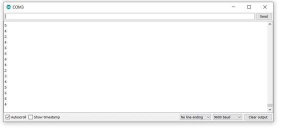
As soon as uploading is finished and with the USB cable still connected to the Arduino, click on the green magnifying glass in the upper right of the IDE to open the Serial Monitor.
Make sure you have the following settings:
Autoscroll: selected
Line ending: No Line ending
Baud: 9600 baud
Place any object in front of the sensor and move it back and forth. You should see the distance readings (in inches) on the Serial Monitor change accordingly.
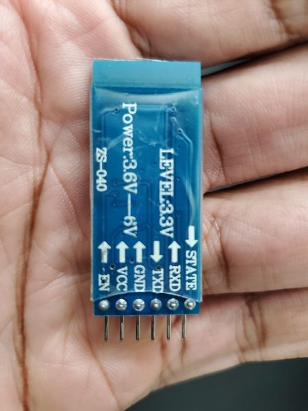
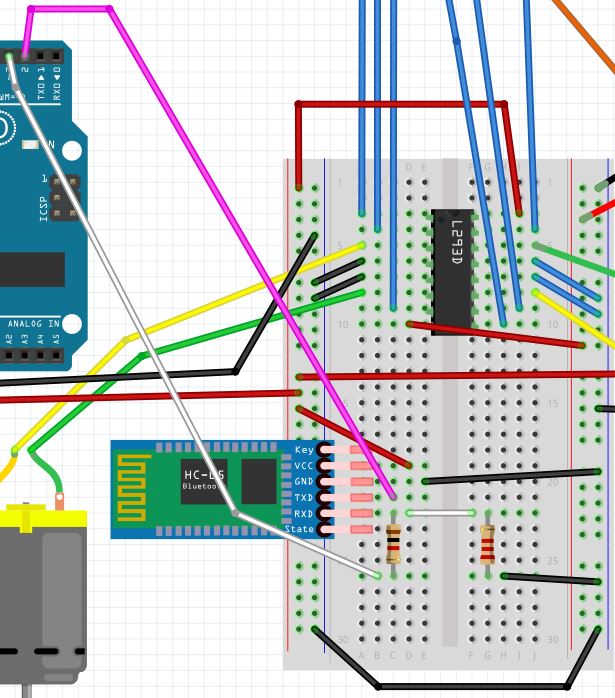
Connect the HC-05 Wireless Bluetooth RF Transceiver (the “Mouth”)
Now we need to connect the HC-05 Wireless Bluetooth RF Transceiver (i.e. bluetooth module).
Connect the VCC pin of the bluetooth module to the red (positive) power rail of your solderless breadboard (the rail connected to the 5V pin of the Arduino).
Note that the bluetooth module can accept an input power supply of 3.6 to 6V, so we could have also connected it to the rail connected to the 6V battery pack (i.e. 1.5V * 4 batteries).
Connect GND to the negative (blue) ground power rail of the solderless breadboard.
Connect the TXD pin (transmitter) of the bluetooth module to digital pin 2 (this will be the receiver RX) on the Arduino.
Connect the RXD pin (receiver) of the bluetooth module to a 1K ohm resistor.
We have to use a resistor because this pin can only handle 3.3V, but the Arduino generates 5V. We don’t want to burn out our bluetooth module!
Connect the 1K ohm resistor to digital pin 3 (this will be the transmitter TX) on the Arduino.
Connect the RXD pin (receiver) of the bluetooth module to a 2K ohm resistor.
This whole 1K ohm + 2K ohm resistor set up is used to divide the 5V input voltage from the Arduino. It is formally called a voltage divider.
Connect the 2K ohm resistor to the negative (blue) ground power rail of the solderless breadboard.
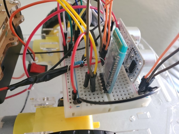
There are a lot of wires and components connected. Double check that everything is wired correctly.
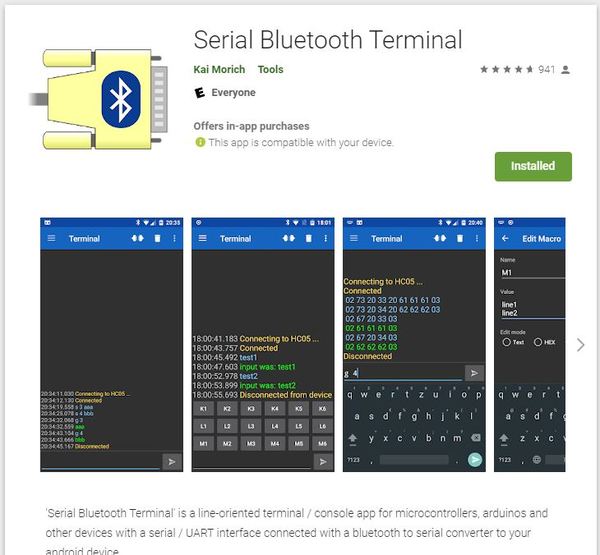
Once you have the HC-05 connected, let’s test it. First, download a bluetooth terminal app on your smartphone. We want to speak with the Arduino via our smartphone. I will download the Serial Bluetooth Terminal app from the Google Play store.
Next, we write the following code and upload it to our Arduino board.
#include <SoftwareSerial.h>
SoftwareSerial EEBlue(2, 3); // RX | TX
void setup()
{
Serial.begin(9600);
EEBlue.begin(9600); //Default Baud rate
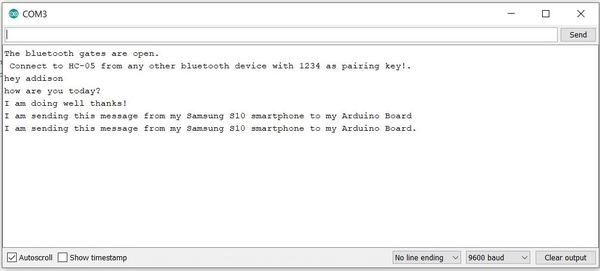
Serial.println("The Bluetooth gates are open.");
Serial.println("Connect to HC-05 with 1234 as key!");
}
void loop()
{
// Feed any data from bluetooth to Terminal.
if (EEBlue.available())
Serial.write(EEBlue.read());
// Feed all data from terminal to bluetooth
if (Serial.available())
EEBlue.write(Serial.read());
}
Click the magnifying glass in the upper right of the IDE to start the program.
Now, on your smartphone, open the Serial Bluetooth Terminal app.
Turn on Bluetooth on your smartphone.
Pair with the HC-05.
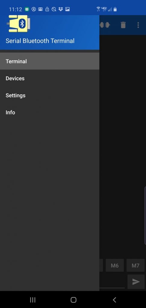
Within the Serial Bluetooth Terminal app, go to the menu on the left-hand side and select Devices.
Select HC-05. Your smartphone will now connect to your HC-05.
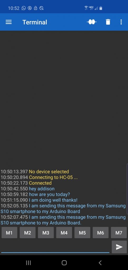
You are now ready to send messages to your Arduino. Type in a message and click the arrow key to send the message to your Arduino.
The message should show up on the Serial Monitor of your Arduino.
Congratulations! You have Bluetooth all set up on your Arduino.
You might be wondering…what the heck does URDF mean? URDF stands for Unified Robot Description Format. URDF is a text-based format (i.e. XML format or Xacro format to be more specific) that is used in ROS to describe all of the parts of a particular robot, including sensors, controllers, actuators, joints, links, etc.
A URDF file tells a computer what a robot looks like in real life (i.e. its physical description). ROS can use the URDF file to create simulations of a robot before the roboticist builds and deploys the robot in the real world.
In this section, we’re going to focus on how to use a URDF file to simulate your wheeled robot. We will use a ready-made URDF file rather than building one from scratch.
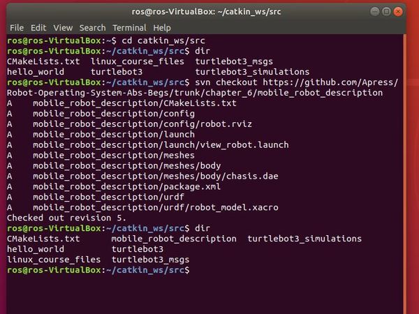
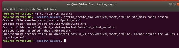
Ok, now we are going to copy a ready-made mobile robot description package (that contains the URDF file we want) into our catkin_ws/src folder. Credit to Lentin Joseph, author of Robot Operating System (ROS) for Absolute Beginners for creating this package.
Open up a new Linux terminal window.
cd catkin_ws/src
Download the mobile_robot_description package from Github to the catkin_ws/src folder.
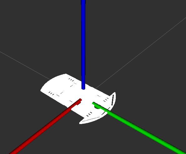
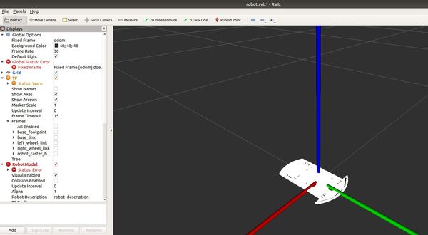
You can use your mouse to see the robot from different angles. It is kind of clunky trying to figure out how to maneuver about, but it is what it is.
To see the actual code of the launch file we just ran, go to the directory the file is located in.
cd ~/catkin_ws/src/mobile_robot_description/launch
gedit view_robot.launch
Note that this project is using ROS Melodic. If you are using a ROS Noetic, you will need to make some modifications to the launch file and URDF files. Credit to one of my avid readers for pointing this out.
* In the launch file
    * Changed `command="$(find xacro)/xacro.py` to `command="$(find xacro)/xacro`
    * Changed `<node name="robot_state_publisher" pkg="robot_state_publisher" type="state_publisher" />` to `<node name="robot_state_publisher" pkg="robot_state_publisher" type="robot_state_publisher" />`
* In the urdf file
    * Changed `<property name=...` to `<xacro:property name=...` (3 places)
So now that you have seen how to run a URDF file, let’s take a look at how we can get our robot to do something useful by writing some code for it.
Program the Arduino (i.e. the “Brain” of the Robot)
Now let’s get our hands dirty with some code. We need to program the Arduino board so that it can:
Read the data from the HC-SRO5 ultrasonic sensor.
Control the motion of the robot.
Communicate with us on our PC.
Here is the code:
// Project Name: Autonomous Obstacle-Avoiding Wheeled Robot

// Author: Addison Sears-Collins

// This code is used to drive a two-wheeled differential
// drive robot.
// You will need to modify the pins according
// to the wiring connections you made when assembling
// the robot.

// Set up Serial connection with Bluetooth module
#include <SoftwareSerial.h>

//(Receiver RX | Trasmitter TX)
SoftwareSerial EEBlue(2, 3);

////////////////////////////////////////////////////////

//Module to interface with the ultrasonic sensor
#define TRIGGER_PIN  12  //Arduino pin connected to TRIG
#define ECHO_PIN     13  //Arduino pin connected to ECHO

////////////////////////////////////////////////////////

//Setup Ultrasonic sensor
void Setup_Ultrasonic()
{

  // Define each pin as an input or output.
  pinMode(ECHO_PIN, INPUT);
  pinMode(TRIGGER_PIN, OUTPUT);

}

////////////////////////////////////////////////////////

 /* Motor driver pin definitions and mappings to Arduino
  *
  *
  */

/* MOTOR PIN DEFINITIONS

ARDUINO DIGITAL PIN ||||  MOTOR DRIVER (L298 PIN)

          5               ENA (Enable 1 - Left Motor)

          6               IN1

          7               IN2

          8               ENB (Enable 2 - Right Motor)

          10              IN4

          9               IN3


*/


#define enableA 5   // Connected to Left Motor
#define MotorA1 6
#define MotorA2 7

#define enableB 8  //Connected to Right Motor
#define MotorB1 9
#define MotorB2 10


///////////////////////////////////////////////////////

//Initializes the motor pins that are defined as MACROS
void Setup_Motors()
{

  // Set up left motor
  pinMode(enableA,OUTPUT);
  pinMode(MotorA1,OUTPUT);
  pinMode(MotorA2,OUTPUT);

  // Set up right motor
  pinMode(enableB,OUTPUT);
  pinMode(MotorB1,OUTPUT);
  pinMode(MotorB2,OUTPUT);

  delay(200);     // Pause 200 milliseconds

  go_forward();  // Move forward

}

////////////////////////////////////////////////////////

//Setup Serial communication
void Setup_Serial(int baud_rate)
{

  Serial.begin(9600);
  EEBlue.begin(9600);  //Default Baud for communications

}


//////////////////////////////////////////////////////
// Returns the distance to the obstacle as an integer
int Update_Ultrasonic()
{

  int distance = 0;
  int average = 0;

  // Grab four measurements of distance and calculate
  // the average.
  for (int i = 0; i < 4; i++) {

    // Make the TRIGGER_PIN LOW (0 volts)
    // for 2 microseconds
    digitalWrite(TRIGGER_PIN, LOW);
    delayMicroseconds(2);

    // Emit high frequency 40kHz sound pulse
    // (i.e. pull the TRIGGER_PIN)
    // by making TRIGGER_PIN HIGH (5 volts)
    // for 10 microseconds
    digitalWrite(TRIGGER_PIN, HIGH);
    delayMicroseconds(10);
    digitalWrite(TRIGGER_PIN, LOW);

    // Detect a pulse on the ECHO_PIN pin 8.
    // pulseIn() measures the time in
    // microseconds until the sound pulse
    // returns back to the sensor.
    distance = pulseIn(ECHO_PIN, HIGH);

    // Speed of sound is:
    // 13511.811023622 inches per second
    // 13511.811023622/10^6 inches per microsecond
    // 0.013511811 inches per microsecond
    // Taking the reciprocal, we have:
    // 74.00932414 microseconds per inch
    // Below, we convert microseconds to inches by
    // dividing by 74 and then dividing by 2
    // to account for the roundtrip time.
    distance = distance / 74 / 2;

    // Compute running sum
    average += distance;

    // Wait 10 milliseconds between pings
    delay(10);
  }

  distance = average / 4;

  Serial.print("u ");
  Serial.print(distance);
  Serial.print("\n");

  int distance_copy = distance;

  // Initialize string
  char str[] = "u ";
  char str_dist[10];

  // Convert distance integer into a string
  sprintf(str_dist, "%d", distance_copy);

  // Add a new line
  char add_new_line[] = "\n";

  // Concatenate to produce the new string
  strcat(str_dist, add_new_line);
  strcat(str, str_dist);

  // Output data to bluetooth
  EEBlue.write(str);

  return distance;

}

//////////////////////////////////////////////////////////
// The following function controls
// the motion of the robot

void Move_Robot(int distance)
{

  // If obstacle <= 2 inches away
  if (distance >= 0 && distance <= 2) {
    go_backwards();   // Move in reverse for 0.5 seconds
    delay(500);

    /* Go left or right to avoid the obstacle*/
    if (random(2) == 0) {  // Generates 0 or 1, randomly
      go_right();  // Turn right for one second
    }
    else {
      go_left();  // Turn left for one second
    }
    delay(1000);
    go_forward();  // Move forward
  }
  delay(50); // Wait 50 milliseconds before pinging again
}

/*
 *  Forwards, backwards, right, left, stop.
 */
void go_forward() {
  //enabling motor A and B
  digitalWrite (enableA, HIGH);
  digitalWrite (enableB, HIGH);

  // Move forward
  digitalWrite (MotorA1, LOW);
  digitalWrite (MotorA2, HIGH);
  digitalWrite (MotorB1, LOW);
  digitalWrite (MotorB2, HIGH);

}
void go_backwards() {
  //enabling motor A and B
  digitalWrite (enableA, HIGH);
  digitalWrite (enableB, HIGH);

  // Go backwards
  digitalWrite (MotorA1,HIGH);
  digitalWrite (MotorA2,LOW);
  digitalWrite (MotorB1,HIGH);
  digitalWrite (MotorB2,LOW);

}
void go_right() {
  //enabling motor A and B
  digitalWrite (enableA, HIGH);
  digitalWrite (enableB, HIGH);

  // Turn right
  digitalWrite (MotorA1, LOW);
  digitalWrite (MotorA2, HIGH);
  digitalWrite (MotorB1,HIGH);
  digitalWrite (MotorB2,LOW);
}
void go_left() {
  //enabling motor A and B
  digitalWrite (enableA, HIGH);
  digitalWrite (enableB, HIGH);

  // Turn left
  digitalWrite (MotorA1,HIGH);
  digitalWrite (MotorA2,LOW);
  digitalWrite (MotorB1, LOW);
  digitalWrite (MotorB2, HIGH);
}
void stop_all() {
  digitalWrite (enableA, LOW);
  digitalWrite (enableB, LOW);
}

//////////////////////////////////////////////////
//Read from Serial Function

void Read_From_Serial()
{
  // Read data from Serial terminal of Arduino IDE
  while(Serial.available() > 0)
    {
     EEBlue.write(Serial.read());
    }

   // Read data from Bluetooth module
   //while(EEBlue.available() > 0)
   // {
   //   Serial.write(EEBlue.read());
   //  int data = Serial.read();

   // }

}

////////////////////////////////////////
//Update all
void Update_all()
{

  int distance = Update_Ultrasonic();

  Read_From_Serial();

  Move_Robot(distance);

}


/////////////////////////////////////////
// Setup function for Arduino
void setup() {

  // Initializes the pseudo-random number generator
  // Needed for the robot to wander around the room
  randomSeed(analogRead(3));

  Setup_Ultrasonic();

    Setup_Serial(9600);

    Setup_Motors();

}
///////////////////////////////////////
// This part loops over and over again
void loop() {


  Update_all();


}
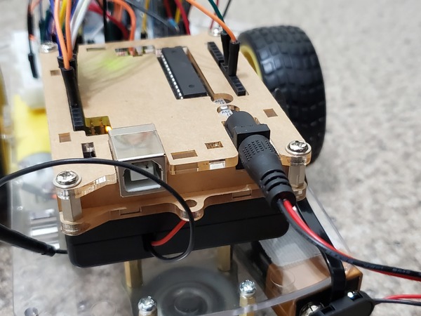
Let’s test the code. With your robot connected to your PC via the USB cord, upload the code to your Arduino board.
Unplug the Arduino from your computer.
Arduino can handle an input supply voltage from 7 – 12V, so let’s add a 9V battery to the board using Velcro fasteners. You can also use some multi-purpose black cable ties.
Before you plug the battery into your Arduino, make sure your Arduino is somewhere on the floor with a lot of space. Hardwood or smooth floors work best. The robot’s motors are not powerful enough to move through thick carpet.
Turn on the motors by switching on the 4×1.5V AA battery pack.
Now plug in the Arduino. The Arduino program you burned into your board will start automatically whenever power is supplied.
If your car does not automatically start, put your hand in front of the ultrasonic sensor to get the car started.
You should see your robot moving around the floor autonomously, avoiding obstacles anytime it gets within two inches of an object. Yay!
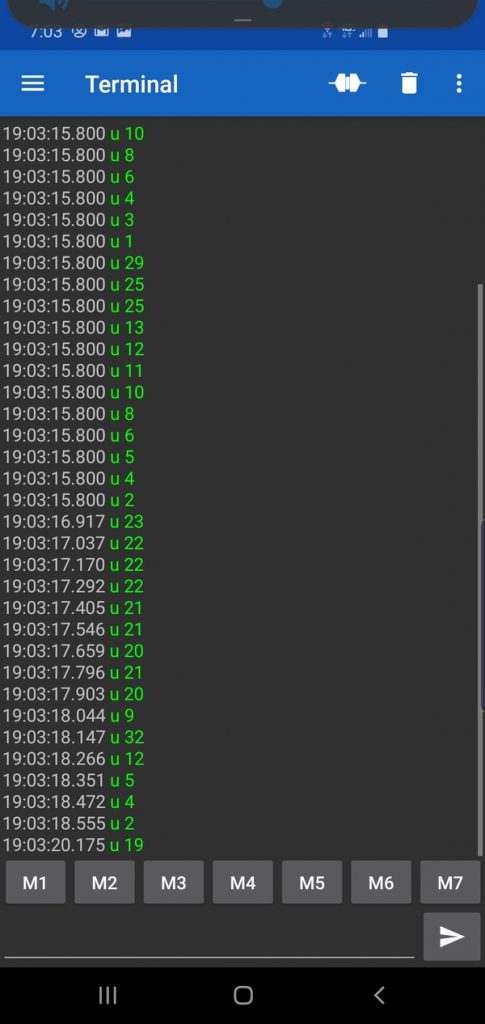
Now, open up your smartphone, and launch the Serial Bluetooth Terminal App. You should see the distance measurements (prefixed with “u “, which means ultrasonic sensor) being printed to your phone.
Whew! That was a lot of work. We are not done yet, but we have come a long way so far.
Now we need to get ROS integrated into our project. Specifically, we want to have our master computer (i.e. PC…desktop computer with Ubuntu Linux installed) “listen” to the raw ultrasonic sensor distance data and publish that data as a message to a ROS topic. All this communication will happen via Bluetooth.
The first thing we need to do is to find the MAC address (i.e. Bluetooth Address) of our HC-05 bluetooth module.
Make sure your Arduino board is powered on (so that the HC-05 Bluetooth light is blinking), and the 4×1.5V AA battery pack is turned off.
If you are on a Windows 10 computer like I am, go to search for Bluetooth and Other Devices and then:
Click Add Bluetooth or other device
Click Bluetooth
Click HC-05
Type the password: 1234
Click Connect
Click Done and close out all windows.
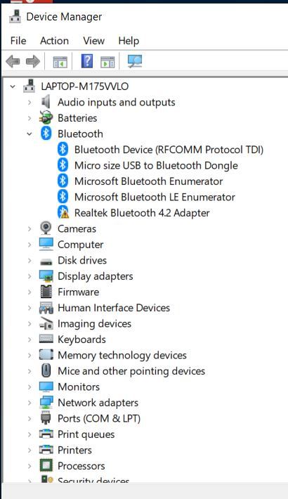
Right-click on the Windows icon in the bottom left of your desktop.
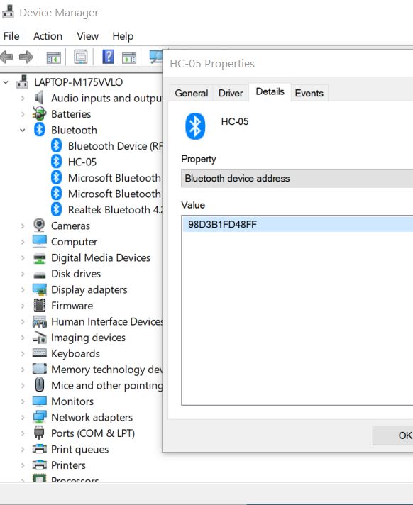
Go to the Device Manager.
Expand the Bluetooth options
Find HC-05
Right-click on the Bluetooth device
Click Properties
Go to the Details tab
Under “Property” select “Bluetooth device address”
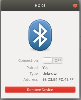
The MAC address for my Bluetooth device is 98:D3:B1:FD:48:FF. Write that address down. We will need it later.
Now, to get Bluetooth enabled in Ubuntu Linux, first, unplug any Bluetooth device that is connected to your PC (i.e. your laptop, personal computer).
Start your PC.
Plug the USB Bluetooth dongle into the USB port on your computer. You cannot use your built-in Bluetooth for Virtual Box. It won’t work. That is why you need the external USB Bluetooth dongle.
Restart your PC.
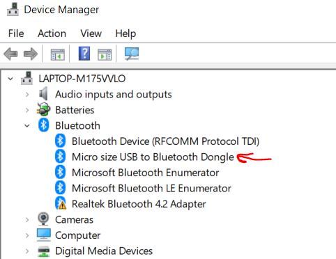
If you are on Windows machine like I am, search for the Device Manager on your PC by right-clicking the Windows icon on your desktop.
Open up the Bluetooth option.
Make sure the Bluetooth dongle is installed on your computer. There should be no exclamation points or weird error messages near it. If you do see that, restart your PC.
If your dongle is still showing weird messages, it is likely because the built-in Bluetooth on your computer is conflicting with it. Bluetooth dongles are notoriously hard to set up on PCs. Restart your computer again, but, before you do that, insert your dongle into a different USB port.
Be persistent in getting your Bluetooth dongle to work (Don’t give up! Robotics requires ironclad persistence and patience to get things working). If everything looks good, it should look like this:
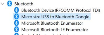
You can also try disabling any Bluetooth options other than the Bluetooth dongle. On a Windows machine, you do this through the Bluetooth option on the Device Manager as well.
Eventually, you will get your dongle enabled. Once you do, disable it by right-clicking on it and clicking “Disable device”. You will see a tiny down arrow over the Bluetooth icon.
Now, launch Ubuntu Linux in your Virtual Machine.
Go back to the Device Manager in Windows, and enable the Bluetooth adapter (right-click on the Bluetooth device and select “Enable device”).
Now return to Ubuntu Linux and, at the menu at the top, go to Devices -> USB.
Select the Bluetooth dongle to enable it. Mine is labeled Broadcom Corp BCM.
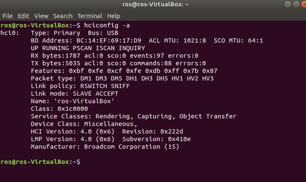
To make sure everything is working, open a new terminal window and type the following command:
hciconfig -a
Make sure the output says “UP RUNNING”. That is how you know everything is working properly.
Now that Bluetooth is enabled, we need to pair our Ubuntu Linux with the robot’s HC-05 Bluetooth module.
Power up your robot (just the Arduino…NOT the motors of your robot).
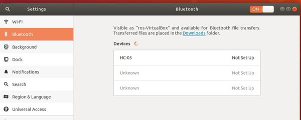
Open the Bluetooth settings by going to your system settings:
gnome-control-center
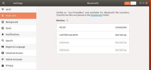
Select Bluetooth.
Now that your Bluetooth panel is open, your computer will begin searching for Bluetooth devices to connect to. Wait until it has found “HC-05”, which is the robot’s Bluetooth. It may take a while, and you might need to restart this Bluetooth panel in System Settings multiple times to get it to work. Bluetooth is fickle like that.
Click the device under the Devices list.
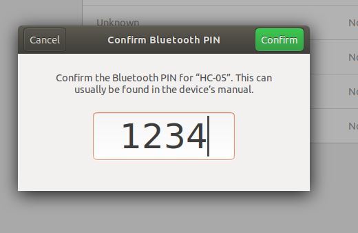
Eventually a panel will show up. Type in the PIN and click confirm. The PIN is 1234, and is the same for all HC-05s.
You will establish a brief connection, then it will get Disconnected. You can click on the HC-05, and it should say “Paired”.
Now, open a new terminal window and download blueman, the Bluetooth Manager. This package helps us to double check to see if Ubuntu Linux is setup to connect to the robot’s Bluetooth.
Type:
sudo apt-get install blueman
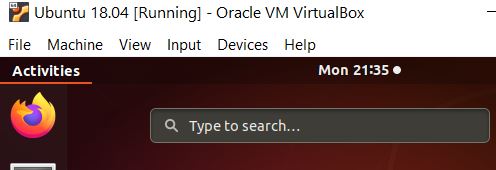
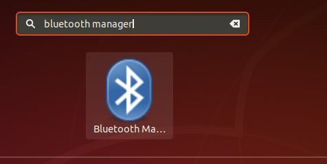
Next, go to Activities on your Desktop, and search for Bluetooth Manager.
Click Install.
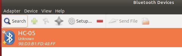
Launch the application and look for the HC-05 (make sure your robot is powered on, otherwise it won’t be visible).
Hover your cursor over HC-05, and it should say “Trusted and Bonded”. You should also see a little key on the upper-left of the Bluetooth icon.
Test the Bluetooth Feed
Let’s see if we can read the ultrasonic sensor data transmitting from our robot.
Open a new terminal window in Ubuntu Liunx, and create a new directory called sandbox.
mkdir sandbox
Move to that directory.
cd sandbox
Create a new file:
touch bluetooth_test.py
Open the file.
gedit bluetooth_test.py
Add this code. Make sure you modify my code with your own robot_bluetooth_mac_address.
#!/usr/bin/env python

'''
File name: bluetooth_test.python

This program tests the Bluetooth connection between
your PC and your robot.
The PC receives messages from the robot
via Bluetooth and prints
those messages to your screen.

Modified from
https://people.csail.mit.edu/albert/bluez-intro/x232.html

Author: Addison Sears-Collins
'''

import bluetooth # Import the python-bluez library
import time

##################################################
# Bluetooth parameters

robot_bluetooth_mac_address = '98:D3:B1:FD:48:FF'
port = 1
pc_bluetooth_handle = None
data_size = 300

######################################################
# Connect the PC's Bluetooth to the robot's Bluetooth

def connect():
  global pc_bluetooth_handle

  while(True):
    try:
      pc_bluetooth_handle = bluetooth.BluetoothSocket(
               bluetooth.RFCOMM)
      pc_bluetooth_handle.connect((
              robot_bluetooth_mac_address, port))
      break;
    except bluetooth.btcommon.BluetoothError as error:
      pc_bluetooth_handle.close()
      print (
         "Could not connect: ", error, "; Retrying in 10s...")
      time.sleep(10)

  return pc_bluetooth_handle

# Connect to the robot's Bluetooth
pc_bluetooth_handle = connect()

#############################################################
# Main code

# If this file is the main (driver) program you are executing
if __name__ == '__main__':

  while(True):
    try:
      # Keep reading data from the robot
      incoming_data_from_robot = pc_bluetooth_handle.recv(
                      data_size)
      time.sleep(0.05)
      print(incoming_data_from_robot)

    except bluetooth.btcommon.BluetoothError as error:
      print ("Caught BluetoothError: ", error)
      time.sleep(5)
      pc_bluetooth_handle = connect()
      pass

  pc_bluetooth_handle.close()
Save the file and then go back to the terminal.
Install the following Bluetooth library. This library is called python-bluez. It handles all the Bluetooth functionalities, including accessing the robot’s Bluetooth that is connected to your PC.
sudo apt-get install python-bluez
Now, let’s change the access permissions on the bluetooth_test.py file so that we can run it.
chmod +x bluetooth_test.py
Now, run the program.
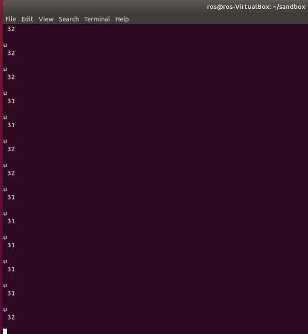
python bluetooth_test.py
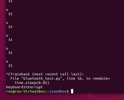
Click on the terminal window, and press CTRL+C at any time to stop the program from running.
To rerun the program, you can press the up arrow on your keyboard until you find ‘python bluetooth_test.py’. Then press ENTER to rerun it.
Troubleshooting Tips
If your program is not working, try the following:
Unplug your Arduino and plug it back in.
Launch a new terminal, and move to the sandbox folder.
Launch bluetooth_test.py (using the python bluetooth_test.py command)
In a terminal window, launch Bluetooth settings using this command: gnome-control-center
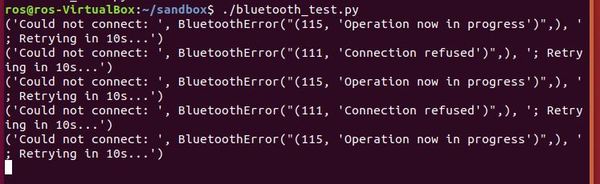
As I mentioned previously, I have no idea why Bluetooth is so fickle. Just keep trying the steps I’ve outlined above until you get the distance data printed to your screen.
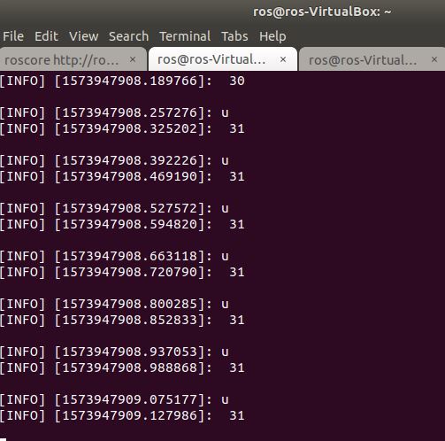
As far as the data feed is concerned, the u means ultrasonic sensor, and the number after that is the distance to the object in front of the robot, in inches. I’m sure there is a way more efficient way to get Bluetooth connected, but this process works for me.
Now, we need to get this program integrated with ROS. We want it to publish that distance data (i.e. ROS message) to a topic and have a Subscriber node subscribe to that topic so that it can receive the distance data. The setup will be very similar to what we did in the hello world program.
Here we’ll create the publisher (“talker”) node which will continually broadcast a message. In plain English, this is a Python program that will read the incoming distance data from Bluetooth and publish that data to a ROS topic named ‘obstacle_distance’. We will name this Publisher node talker.py.
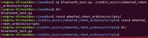
So that we don’t have to start from scratch, copy bluetooth_test.py into your ~/catkin_ws/src/wheeled_robot_arduino/scripts folder.
Now let’s rename bluetooth_test.py. Its new name will betalker.py. talker.py will be the Publisher node.
mv bluetooth_test.py talker.py
Now, edit the file.
gedit talker.py
Here is the full code.
#!/usr/bin/env python

import rospy # ROS Python library
from std_msgs.msg import String

import bluetooth # Import the python-bluez library

##################################################
# Bluetooth parameters

robot_bluetooth_mac_address = '98:D3:B1:FD:48:FF'
port = 1
pc_bluetooth_handle = None
data_size = 300

##################################################
# Publisher List

# Ultrasonic distance sensor data will
# be published to a ROS topic named
# obstacle_distance using the message
# type String. Other data types like
# Float32, Int64, etc. are possible in other
# applications. Here we use String.
ultrasonic_handle = rospy.Publisher(
         'obstacle_distance', String, queue_size=10)

####################################################
# Launch the ROS node

rospy.init_node('talker', anonymous=True)
rospy.loginfo("Starting Talker Node")


#####################################################
# Connect the PC's Bluetooth to the robot's Bluetooth

def connect():
  global pc_bluetooth_handle

  while(True):
    try:
      pc_bluetooth_handle = bluetooth.BluetoothSocket(
                                 bluetooth.RFCOMM)
      pc_bluetooth_handle.connect((
                    robot_bluetooth_mac_address, port))
      break;
    except bluetooth.btcommon.BluetoothError as error:
      pc_bluetooth_handle.close()
      rospy.logwarn(
       "Could not connect: ", error, "; Retrying in 10s...")
      rospy.sleep(10)

  return pc_bluetooth_handle

pc_bluetooth_handle = connect() # Connect to robot's Bluetooth

#############################################################
# Main code

# If this file is the main (driver) program you are executing
if __name__ == '__main__':

  while not rospy.is_shutdown():
    try:
      # Keep reading data from the robot
      incoming_data_from_robot = pc_bluetooth_handle.recv(
                              data_size)
      rospy.loginfo(incoming_data_from_robot)
      ultrasonic_handle.publish(incoming_data_from_robot)
      rospy.sleep(0.05)

    except bluetooth.btcommon.BluetoothError as error:
      rospy.logerr("Caught BluetoothError: ", error)
      time.sleep(5)
      pc_bluetooth_handle = connect()
      pass

  pc_bluetooth_handle.close()
Save the file and then close the window.
Now, we need to build the node.
cd ~/catkin_ws
catkin_make
Open a new terminal window.
Plug in the Arduino board on your robot to get Bluetooth started.
Launch ROS.
roscore
Open a new terminal tab and run your ROS publisher node named talker.py.
rosrun wheeled_robot_arduino talker.py
As soon as you run the command above (you have to act within about 10 seconds), open up a new terminal window and type:
gnome-control-center
Make sure you are on your Bluetooth settings. The Bluetooth panel looks like this:
You might need to try executing this command numerous times, opening and closing your Bluetooth panel while the code is trying to execute. As I’ve mentioned before in this tutorial, Bluetooth is fickle and doesn’t often work on the first try (but don’t give up! It WILL work).
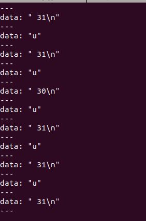
Let’s check out the obstacle_distance ROS topic now to see what messages are publishing to it. While the code is still running, open up a new terminal tab and type:
rostopic echo obstacle_distance
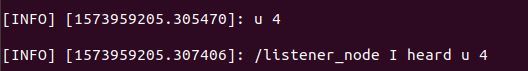
Here is the output. We use the u separator (which stands for ultrasonic) to separate the distance readings.
Congratulations! You have build a complete ROS Publisher Node from scratch.
Now, instead of opening up a new window to check out the obstacle_distance topic using the command above, how about we build a ROS Subscriber node that subscribes to the topic and prints out what it sees? We’ll call this Subscriber node listener.py. Let’s build it now!
Press CTRL+C on all open tabs and windows to kill all processes. You can also disconnect power from the Arduino on your robot.
Open a new terminal, and go to your ~/catkin_ws/src/wheeled_robot_arduino/scripts folder.
Create a new file named listener.py.
gedit listener.py
Type the following code and save.
#!/usr/bin/env python
import rospy
from std_msgs.msg import String

def callback(data):

    # Print the data that is heard from the ROS topic
    rospy.loginfo(
        rospy.get_caller_id() + " I heard %s", data.data)

def listener():

    # Initialize the node
    rospy.init_node('listener', anonymous=True)

    # Subscribe to the obstacle_distance topic
    rospy.Subscriber("obstacle_distance", String, callback)

    # keeps python from exiting until this node is stopped
    rospy.spin()

if __name__ == '__main__':
    listener()
Change its permissions.
chmod +x listener.py
Now, we need to build the node.
cd ~/catkin_ws
catkin_make
Open a new terminal window.
Plug in the Arduino board on your robot to get Bluetooth started.
Launch ROS.
roscore
Open a new terminal tab and run your ROS publisher node named talker.py.
rosrun wheeled_robot_arduino talker.py
Immediately, go to a new terminal window, and open your Bluetooth panel.
gnome-control-center
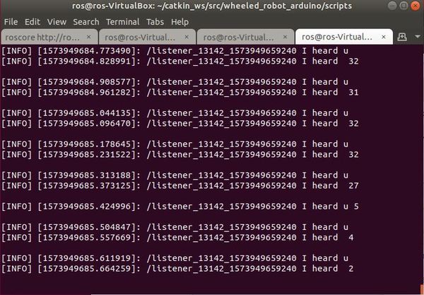
Now, in a new terminal window, run the ROS subscriber node named listener.py.
Launching talker.py and listener.py separately can be a bit tedious. How about we execute both files from a single script? Let’s do that. We will use a ROS launch file, which will speed up the launch process of our programs.
Go to your wheeled_robot_arduino package.
roscd wheeled_robot_arduino
Create a folder called ‘launch’.
mkdir launch
Move to the launch folder.
cd launch
Create a new file called talker_listener.launch.
gedit talker_listener.launch
Type the code below, and save it. This file will run both Python programs, talker.py and listener.py.
Immediately, go to a new terminal window, and open your Bluetooth panel.
gnome-control-center
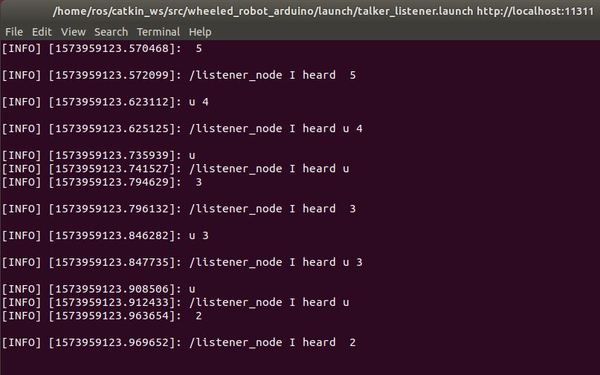
Watch the talker.py (ROS publisher node) publishing to the /obstacle_distance topic and listener.py (ROS subscriber node) echoing back what it is hearing.
You will notice that, unlike when we used the Serial Bluetooth Terminal app, the data isn’t always lined up because the speed at which the program is executing within Ubuntu Linux is lagging relative to the speed at which data (e.g. u 5) is coming in via Bluetooth. This is perfectly OK for our purposes in this tutorial, but for you perfectionists out there, you can go back to your Arduino code and remove the ‘u’ character that prints just prior to the distance data. In this way, the only thing that will print out is the distance value (i.e. ‘5’ instead of ‘u 5’).
Grand Finale – Launch Your Autonomous Wheeled Robot
Ok, now we are ready to put it all together.
We will have our robot move around the room autonomously, avoiding obstacles along the way. While it is doing that, it is feeding obstacle distance data back to your PC via Bluetooth. This data is being read by the Publisher node, talker.py. talker.py is publishing this data to the obstacle_distance ROS topic. listener.py is subscribed to the obstacle_distance topic. It ‘hears’ the distance readings and prints these to the screen.
Plug your Arduino into the 9V battery power source.
Place the robot somewhere in an open space on the floor.
Open a new terminal window in Ubuntu Linux and type:
Immediately, go to a new terminal window, and open your Bluetooth panel.
gnome-control-center
Make sure the data is flowing into your Linux terminal.
Now, turn on your robot’s motors by switching the 4 x 1.5V battery pack to ON.
Watch your robot move around the room!
Check out the terminal to see the printout of the distance data!
Congratulations! We have come a long way. We have successfully designed and developed an autonomous wheeled robot using ROS…from scratch!
The complex robots, like the ones you might have seen being built by companies like Amazon, iRobot, or Boston Dynamics, have bigger sensors, more code, more wiring, etc…but, at their core, they work using the same fundamentals that drive the autonomous robot we have just built. They all sense the world, think about what they have sensed, and then act.
I hope you have learned a lot along the way. Keep building!


