
Definition
In the previous tutorial, we discussed how coordinate frames rotate relative to each other. The goal was to find the orientation of the end effector of a robot (gripper, paint brush, robotic hand, vacuum suction cup, etc.) relative to the base of the robot.
However, when a robotic arm moves around in the world, orientation is just half the puzzle. The end effector changes position as well. To account for this change in the position of the end effector, we use what is called a displacement vector.
A vector is a list of numbers. In robotics, we typically use three numbers (all organized in a single column), to represent displacement (i.e. change in position) of one frame relative to another frame in the x, y, and z directions.
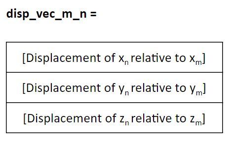
We’ll use the following notation to represent the displacement of coordinate frame n relative to coordinate frame m.
Example 1 – Displacement in the x direction
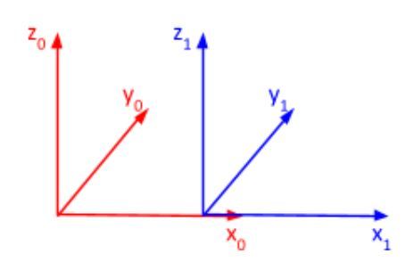
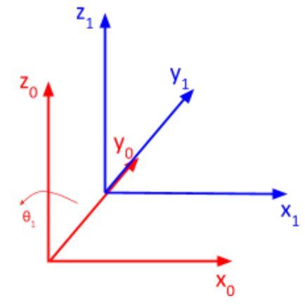
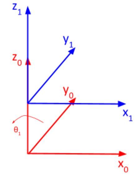
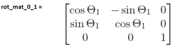
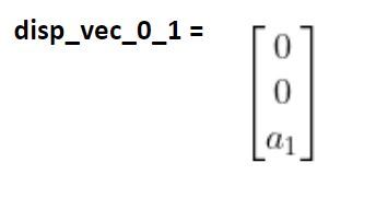
We have two coordinate frames: frame 0 and frame 1. Let’s do a brief review of how to find rotation matrices before we get to the displacement vector.
Rotation Matrix
You can see that frame 1 has no rotation relative to frame 0.
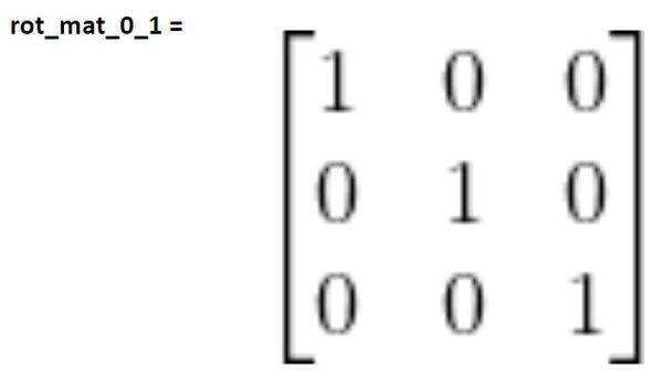
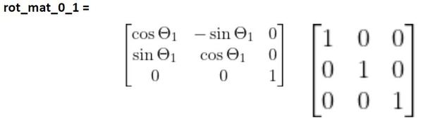
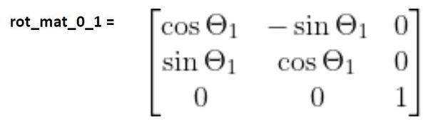
Therefore, the first term we’ll use to calculate the rotation matrix from frame 0 to 1 will be the identity matrix. This rotation matrix shows how the axes of frame 1 project onto the axes of frame 0 when there is no rotation.
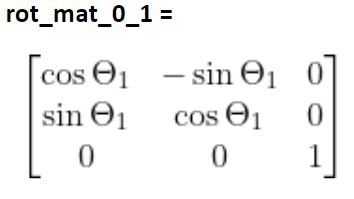
Now that we’ve converted the axes, we need to complete the derivation of the rotation matrix from frame 1 to 0 by finding the matrix that takes into account the rotation of frame 1 due to changes in θ1.
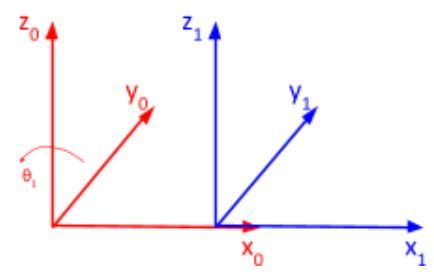
θ1 is a rotation around the z0 axis. We therefore need to multiply the matrix we found above by the standard form of the z rotation matrix.
Displacement Vector
As mentioned earlier, rotation is just half the puzzle. Now that we know how frame 1 is rotated relative to frame 0, we now need to know how frame 1 is displaced relative to frame 0.
Our displacement vector needs to have three elements:
- Change in the position along the x-direction
- Change in the position along the y-direction
- Change in the position along the z-direction
For example, let’s say that the distance from the origin of frame 1 to the origin of frame 0 is a. There is no displacement in the y and z directions.
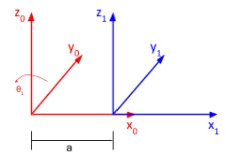
Here is the displacement vector:
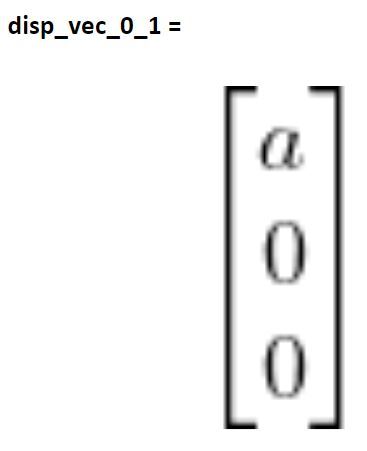
No matter how much θ1 changes (i.e. frame 1 rotates relative to frame 0), the origin of frame 1 will remain in the same position. Thus, the displacement vector will always remain the same.
Now let’s take a look at another example.
Example 2 – Displacement in the y direction
Rotation Matrix
You can see that frame 1 has no rotation relative to frame 0.
Therefore,
Displacement Vector
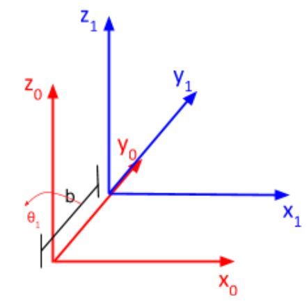
In the graphic below, all we have is displacement in the y direction. I’ll call this distance b.
Here is the displacement vector:
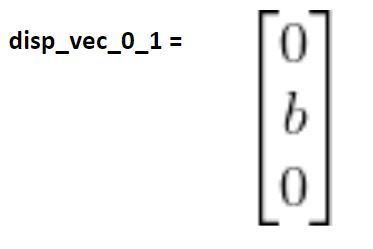
No matter how much frame 1 rotates, the distance between the origins of both frames will remain the same. So the displacement vector will always be what you see above regardless of the value of the joint variable θ1.
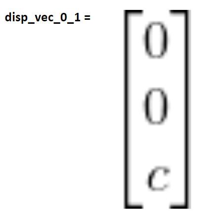
Example 3 – Displacement in the z direction
Rotation Matrix
You can see that frame 1 has no rotation relative to frame 0.
Therefore,
Displacement Vector
All we have is displacement in the z direction. I’ll call this distance c.
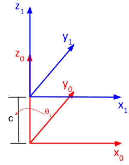
Here is the displacement vector:
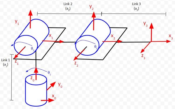
Example 4 – Two Degree of Freedom Robotic Arm
Now, let’s take a look at some real-world examples. We’ll draw the displacement vector for a two degree of freedom robotic arm.
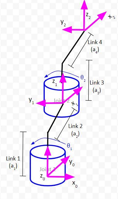
Here is a kinematic diagram for a two degree of freedom robotic arm.
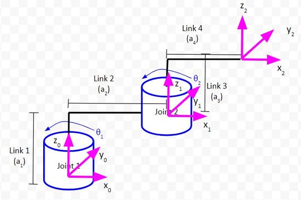
Rotation Matrix
Here are the rotation matrices for this two-degree of freedom manipulator.
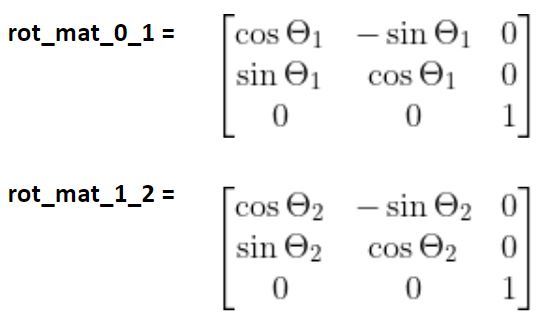
The complete rotation matrix is as follows:
rot_mat_0_2 = (rot_mat_0_1)(rot_mat_1_2)
Displacement Vector
Let’s determine the displacement vector from frame 0 to frame 1. We need to find the displacement in the x0, y0, and z0 direction.
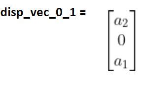
The problem with this displacement vector above though is that it only makes sense when θ1 = 0 degrees. What happens when θ1 = 90 degrees?
You see that the displacement vector is different when θ1 = 90 degrees. When θ1 changes, the origin of frame 1 rotates around z0. Therefore, the displacement of the origin of frame 1 relative to the origin of frame 0 changes as the joint variable changes.
To be able to control the position of the end effector in code, we need to find a displacement vector that will be correct regardless of the value of θ1. To do that, we have to make the values in the displacement vector dependent on the joint variables θ.
Let’s see how to do this now.
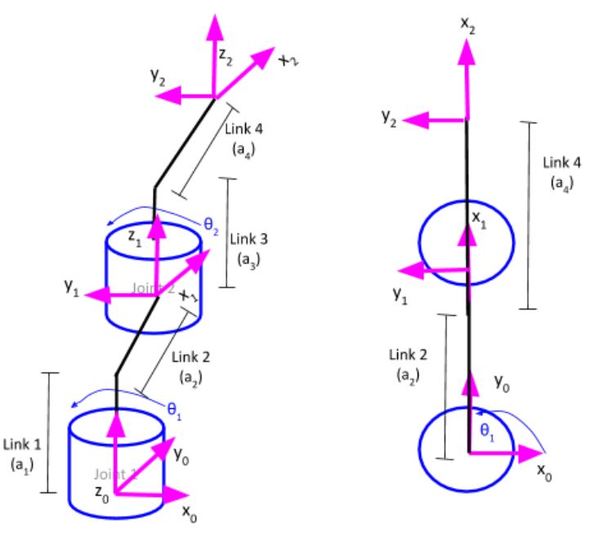
We will draw an aerial view of the kinematic diagram we just worked with. The birds-eye view would look like this:
Now let’s assume that θ1 = 45 degrees.
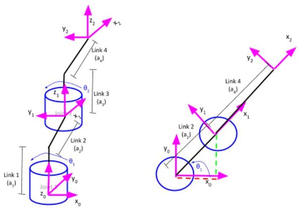
What would our displacement vector be for the displacement of frame 1 relative to frame 0?
Using trigonometry, we know that:
- cos(θ1) = (length of red dashed line) / a2 [displacement in the x0 direction]
- sin(θ1) = (length of green dashed line) / a2 [displacement in the y0 direction]
- a1 [displacement in the z0 direction]
The red dashed line represents the displacement of frame 1 relative to frame 0 in the x0 direction.
The green dashed line represents the displacement of frame 1 relative to frame 0 in the y0 direction.
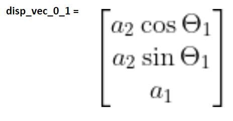
Therefore, using algebra to solve for the length of both of these dashed lines, our displacement vector is:
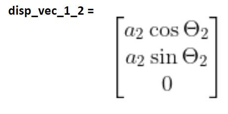
Now let’s look at the displacement from frame 1 to frame 2. We’ll just examine both of these frames and forget frame 0 which we’ve already taken care of.
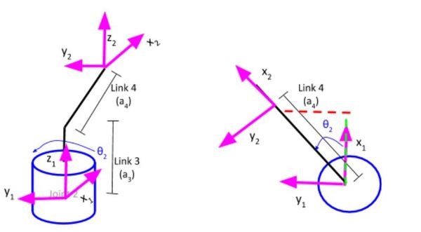
Using trigonometry, we know that:
- cos(θ2) = (length of green dashed line) / a4 [displacement in the x1 direction]
- sin(θ2) = (length of red dashed line) / a4 [displacement in the y1 direction]
- a3 [displacement in the z1 direction]
Example 5 – Cartesian Robot
Now, let’s derive the displacement vectors for a cartesian robot.
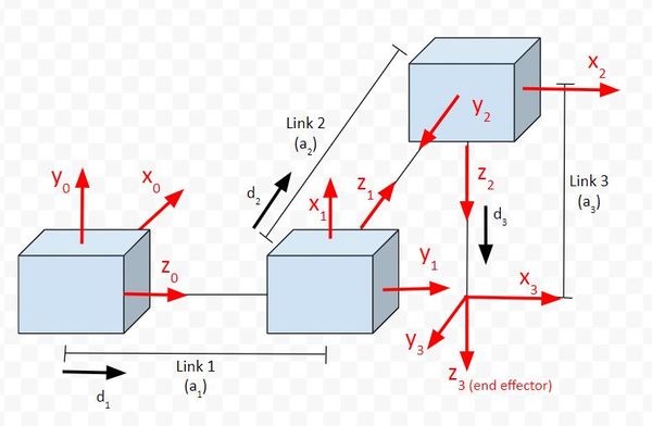
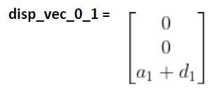
Let’s examine the displacement vector of frame 1 relative to frame 0. The kinematic diagram above shows the position and orientation of all the joints and links when the joint variable values are all 0 (i.e. the prismatic joints are in their home position…unextended).
Since we have only prismatic joints in this case, the direction of displacement will always stay constant.
In our case, the only change to the value of displacement will be along the z0 axis. The value of this displacement is a1 + d1, where d1 represents the amount of extension of the joint when the cartesian robot is powered on.
Therefore,
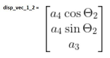
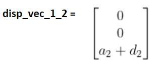
Following the same logic, the displacement vector of frame 1 to frame 2 is…
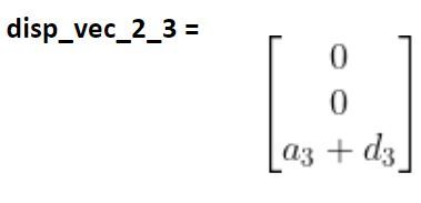
And finally, let’s write the displacement vector that represents the displacement from the origin of frame 2 to the origin of frame 3.
Example 6 – Articulated Robot
We’ll start by deriving the displacement vector from frame 0 to frame 1. We have to look and see how the position of the origin of frame 1 changes when the value of θ1 changes.
Does it change? No.
No matter what value θ1 is, the origin will stay in the exact same position in 3D space. In this case, we have a fixed displacement vector. There is only displacement along the z0 axis, therefore:
Let’s take a look at the displacement from the origin of frame 1 to the origin of frame 2. We have to look and see how the position of the origin of frame 2 changes when the value of θ2 changes.
Imagine θ2 = 45 degrees. You can see that the origin of frame 2 changed along the y1 axis as well as the x1 axis. There was no change along the z1 axis.
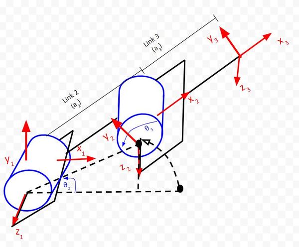
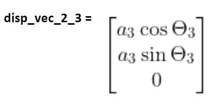
Now let’s look at the displacement of the origin of frame 3 from the origin of frame 2. The same logic applies:
References
Credit to Professor Angela Sodemann for teaching me this stuff. Dr. Sodemann is an excellent teacher (She runs a course on RoboGrok.com). On her YouTube channel, she provides some of the clearest explanations on robotics fundamentals you’ll ever hear.