
In this tutorial, we’ll learn how to find the rotation matrices for different types of robotic arms. Rotation matrices help us represent the orientation of a robotic arm (i.e. which way a robotic arm is pointing).
Rotation matrices will help us determine how the end effector of a robot (i.e. robotic gripper, paint brush, robotic hand, vacuum suction cup, etc.) changes orientation due to changes in the servo motor angles (i.e. joint variables).
Prerequisites
- You have Python installed and know how to write and run a basic program (e.g. “Hello World”).
- If you’re using Windows or MacOS, you can download Anaconda and get access to Python that way.
- You have NumPy installed. NumPy is a scientific computing library for Python.
- If you’re using Windows or macOS, you can download Anaconda and then use the following command to install NumPy (conda install numpy).
- If you’re using Linux, you can use this command in the terminal window (pip3 install numpy).
- You know how to multiply matrices (if you don’t know, there are a bunch of videos on YouTube that explain how to do it).
Getting Started
In robotics, the orientation of a robotic system can be represented in mathematical terms using rotation matrices. Rotation matrices transform the coordinate axes (e.g. x, y, and z) representing the orientation of a 3D object in one frame to the coordinate axes of another frame.
The definition of a rotation matrix is important, so be sure to refer back to it so you keep the big picture in mind.
Now, before you proceed in this section, read through my two posts where I explain:
In those cases, we use a robotic car, but the same principles apply to a robotic arm.
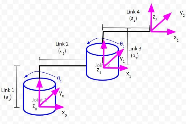
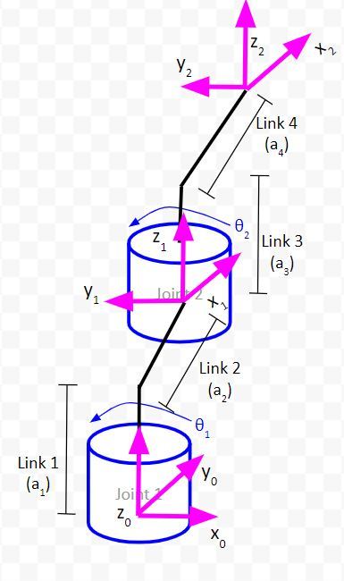
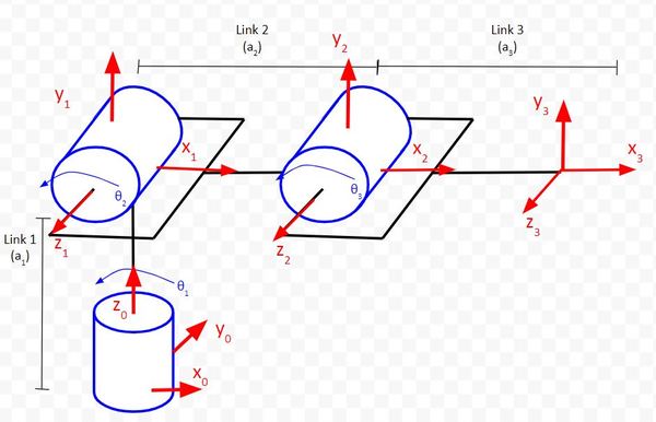
In the case of a two degree of freedom robotic arm, we have three coordinate frames (i.e. reference frames).
- The base coordinate frame (x0, y0, and z0 axes in the image below) could be our global reference frame.
- We then have a local reference frame (x1, y1, z1) that is rotated at an angle from the global reference frame.
After that, we have another local reference frame (x2, y2, z2) that is rotated relative to the local reference frame before it (x1, y1, z1).
Imagine the base reference frame (x0, y0, z0) is a person. Our base frame might ask, ”Hey, I see the (x2, y2, z2) reference frame is rotated. What is the orientation of that reference frame in terms of my own reference frame?”
To answer that question, we would need to convert the (x2, y2, z2) frame to the (x1, y1, z1) frame using a rotation matrix. We would then convert the (x1, y1, z1) frame to the (x0, y0, z0) frame using another rotation matrix. We would then have our answer.
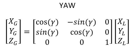
Specifically, in our example above, when any of the servos above move, the only rotation you will have is rotation around the z-axes. There is no rotation around either the x or y-axes with any of these joints. The matrix that enables you to convert between two reference frames when you only have rotation around the z-axis is below where the joint variables of your servo motors (θ) would be plugged into where you see γ:
You can see how rotation matrices are powerful tools in robotics. With rotation matrices, we can calculate the orientation of a robotics gripper (i.e. the end effector, (x2, y2, z2) ) in terms of the base reference frame (x0, y0, and z0) using a sequence of matrix multiplications. This is particularly useful for applications where you need the gripper to point a particular direction (e.g. a robotic arm painting an automobile).

Example 1 – Two Degree of Freedom Robotic Arm
Let’s draw the rotation matrices for this two-degree of freedom manipulator.
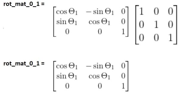
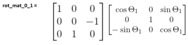
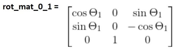
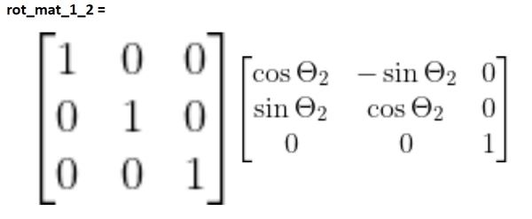
As θ1 changes, frame 1 will rotate around the z0 axis. We can therefore represent this rotation using the standard z rotation matrix. We also need to multiply this matrix by the matrix that represents the projection of frame 1 on frame 0 when the joint variable is θ1 = 0 degrees.
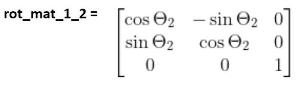
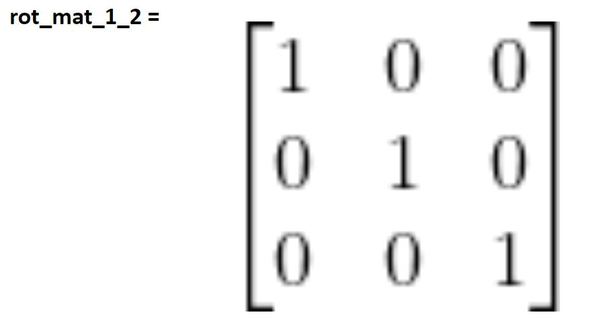
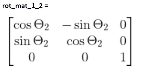
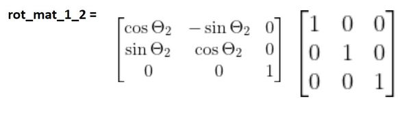
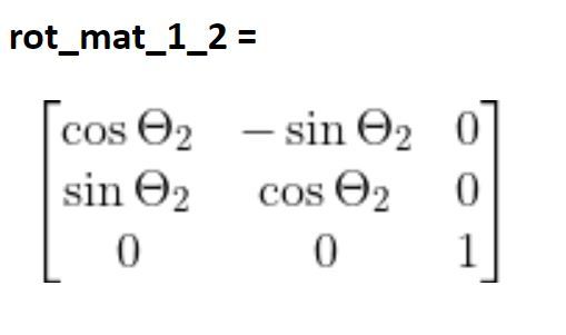
Following the same logic, the rotation matrix between frame 1 and frame 2 is:
The complete rotation matrix is as follows:
rot_mat_0_2 = (rot_mat_0_1)(rot_mat_1_2)
Let’s look at an example of how rotation matrices work in actual code. We’ll use Python.
Open up a new Python file and write the following code. As a guideline, the matrix “rot_mat_0_1” in the code below is the rotation matrix that would convert the (x1, y1, z1) frame to the base frame (x0, y0, z0). The matrix follows the format below where (xL, yL, zL) is (x1, y1, z1) and (xG, yG, zG) is (x0, y0, z0). γ is the servo (joint) angle.
In the code, make sure:
- servo_0_angle = 0
- servo_1_angle = 0
import numpy as np # Scientific computing library

# Project: Calculating Rotation Matrices
# Author: Addison Sears-Collins
# Date created: August 1, 2020

# Servo (joint) angles in degrees
servo_0_angle = 0 # Joint 1
servo_1_angle = 0 # Joint 2

# Convert servo angles from degrees to radians
servo_0_angle = np.deg2rad(servo_0_angle)
servo_1_angle = np.deg2rad(servo_1_angle)

# Define the first rotation matrix.
# This matrix helps convert frame 1 to frame 0.
# There is only rotation around the z axis of servo_0.
rot_mat_0_1 = np.array([[np.cos(servo_0_angle), -np.sin(servo_0_angle), 0],
                        [np.sin(servo_0_angle), np.cos(servo_0_angle), 0],
                        [0, 0, 1]])

# Define the second rotation matrix.
# This matrix helps convert the
# end-effector frame (frame 2) to frame 1.
# There is only rotation around the z axis of servo_1 (joint 2).
rot_mat_1_2 = np.array([[np.cos(servo_1_angle), -np.sin(servo_1_angle), 0],
                        [np.sin(servo_1_angle), np.cos(servo_1_angle), 0],
                        [0, 0, 1]])

# Calculate the rotation matrix that converts the
# end-effector frame to the servo_0 frame.
rot_mat_0_2 = rot_mat_0_1 @ rot_mat_1_2

# Display the rotation matrix
print(rot_mat_0_2)
Now, run the code. Your output should be the identity matrix. What does this mean? It means that when both servo angles are 0 (remember in a kinematic diagram, we assume that all servo angles are 0 degrees), there is no rotation between frame 0 and frame 2.
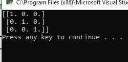
When you look at the kinematic diagram below, you can see that the third reference frame (frame 2) has the exact same orientation as the first reference frame (frame 0).
Now, let’s take a look at a case where θ1 = 90 degrees (Servo 0 angle). Here is the kinematic diagram.
Make sure:
- servo_0_angle = 90
- servo_1_angle = 0
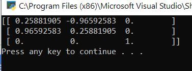
Here is the output:
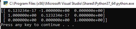
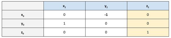
The value in row 0, column 0 is extremely small. We can call it 0. Let’s put the output above in a table to make it easier to see.
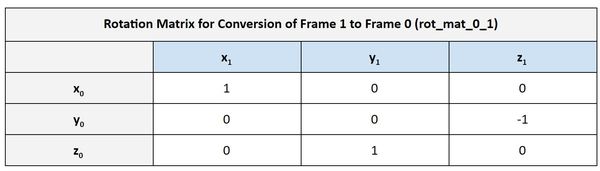
Rotation Matrix From Frame 0 to Frame 2 When θ1 = 90 degrees
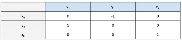
The table above is another way to look at a rotation matrix. It shows the projection of the x2, y2, and z2 axes on the x0, y0, z0 axes, respectively. I use the word projection here because what a rotation matrix does is project the coordinate axes of one reference frame onto the coordinate axes of another reference frame…in this case, projecting the axes of frame 2 onto the axes of frame 0.
- If an axis in one frame points in the same direction as an axis in another frame, we put in a 1 in that cell of the matrix.
- If an axis in one frame points in the opposite direction as an axis in another frame, we put a -1 in that cell of the matrix.
- If an axis in one frame is perpendicular to an axis in another frame, we put a 0 in that cell of the matrix.
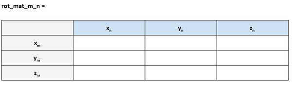
The template for a rotation matrix in this form is below. We want to know the projection of the n coordinate frame on the m coordinate frame. Another way to say this is that rot_mat_m_n is the rotation of frame n relative to frame m:
The yellow cells below, for example, tells us that the projection of x2 on y0 is 1. Does this make sense when we look at the kinematic diagram?
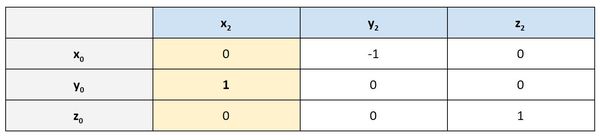
We can see in the diagram above that x2 has the same orientation (i.e. pointing exact same direction) as y0. So it makes sense that the value in the rotation matrix is 1.
Let’s look at another example. Column 2 shows that the projection of y2 on x0 is -1. Does this make sense?
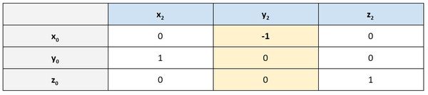
We can see in the kinematic diagram below that y2 points in the exact opposite direction of x0. It therefore makes sense that we have -1 there in the second column.
You can see in the third column of the rotation matrix that z2 and z0 both have the same orientation. Therefore, we have 1 in that column (and 0s in the other rows of that column).
You can change the value of the joint variables to whatever angle you want. Try:
- servo_0_angle = 12
- servo_1_angle = 63
What was your output? Did you get this?
Example 2 – Cartesian Robot
Let’s see how to create the rotation matrices for the cartesian robot.
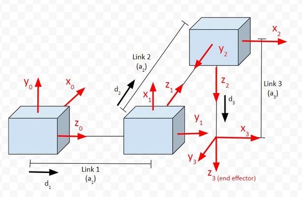
Our goal is to find a rotation matrix that can help us convert frame 3 (the end-effector frame) to frame 0 (the base frame). My notation for this rotation matrix is rot_mat_0_3.
To find rot_mat_0_3, we need to first find the “internal” rotation matrices. That is the rotation matrices from frame 3 to frame 2, from frame 2 to frame 1, and then from frame 1 to frame 0. We then multiply these rotation matrices together to get the final rotation matrix.
Here is how all this looks mathematically:
rot_mat_0_3 = (rot_mat_0_1)(rot_mat_1_2)(rot_mat_2_3)
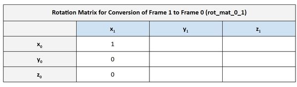
Let’s go through this step by step. First, let’s find rot_mat_0_1.
The first column represents the projection x1 on each of the axes of frame 0. We can see that x1 has the same orientation as y0. We put a 1 in that corresponding cell in the rotation matrix. We put a 0 in the other cells because x1 is perpendicular to x0 and z0. In this case, we are assuming the joint variables are all 0…i.e. none of the linear actuators are extended from their 0 position.
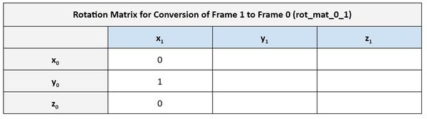
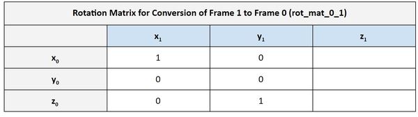
Using the same logic above, we can fill out the second column of the table. y1 has the same orientation as z0.
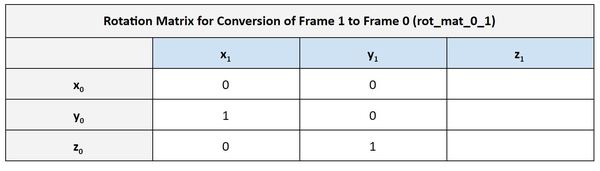
We then finish the third column of the rotation matrix.

Therefore in the case where the joint variables are all 0.
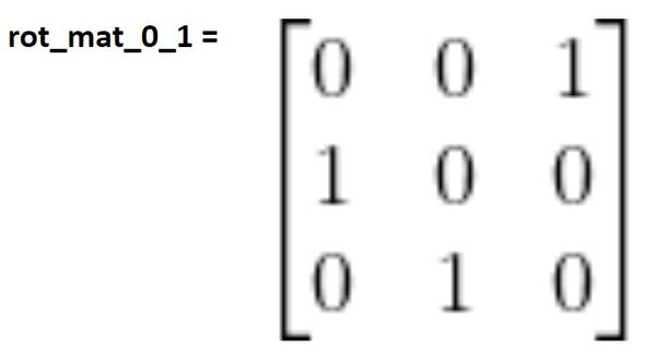
That matrix above tells us how frame 1 converts to frame 0 when the joint variable is 0 (i.e. the linear actuator is not extended).
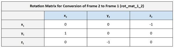
Now let’s create the rotation matrix between frame 2 and frame 1. Remember our diagram:
You can see that frame 3 has the same orientation as frame 2. Therefore, we use the identity matrix.
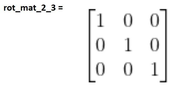
Remember the matrix above tells us how frame 3 converts to frame 2 when the joint variable is 0 (i.e. the linear actuator is not extended). However, since there is no rotation for any of the joints (since they are all prismatic joints), the three rotation matrices we’ve derived above will be the exact same for any value of the joint variable.
Example 3 – Articulated Robot
Now let’s create the rotation matrices for an articulated manipulator.
Our goal is to find a rotation matrix that can help us convert frame 3 (the end-effector frame) to frame 0 (the base frame). My notation for this rotation matrix is rot_mat_0_3.
rot_mat_0_3 = (rot_mat_0_1)(rot_mat_1_2)(rot_mat_2_3)
Let’s go through this step by step. First, let’s find rot_mat_0_1.
The first column represents the projection x1 on each of the axes of frame 0. We can see that x1 has the same orientation as x0. We put a 1 in that corresponding cell in the rotation matrix. We put a 0 in the other cells because x1 is perpendicular to y0 and z0.
Using the same logic above, we can fill out the second column of the table. y1 has the same orientation as z0.
We then finish the third column of the rotation matrix.
The matrix above tells us how frame 1 converts to frame 0 when the joint variable is 0 (i.e. the linear actuator is not extended). But are we done yet? No we are not.
The matrix above only tells us how frame 1 converts to frame 0 when the joint variables (i.e. servo angles) are at 0 degrees. All we’ve done so far is convert one axes to another, but we haven’t accounted for the fact that a revolute joint (in comparison to the prismatic, linear actuator joints we worked with in the cartesian robots case) rotates to different angles when the articulated robot (e.g. robotic arm) is in action.
If all we used was the matrix above, that wouldn’t be sufficient because we have no way of converting frame 1 to frame 0 when the robot is in action. We need to add another matrix that takes into account the rotation of the base frame servo (i.e. changes in θ1).
Look at the diagram above. You can see that frame 1 can rotate in response to changes in θ1. When θ1 changes, it causes rotation around both the (I’ve linked below to the standard form of the y and z rotation matrices…derivation included in case you’re interested where these matrices come from):
Which matrix do we use?
It doesn’t matter. However, which one we choose impacts the order of the matrix multiplication. Remember that, unlike regular multiplication, the order in which two matrices are multiplied matters.
If you use the standard z-rotation matrix (assume rotation around the z0 axis of frame 0), you would place that before the matrix we found earlier.
If you use the standard y-rotation matrix (assume rotation around the y1 axis of frame 1), you would place that after the matrix we found earlier (i.e. on the right). That would look like this:
Multiplying the matrices above, together, we get:
The middle column of the matrix above represents the projection of the y1 axis onto frame 0. You can see that, no matter what servo 0 (i.e. joint 1) does, y1 will always point in the same direction as z0.
Now let’s create the rotation matrix between frame 2 and frame 1. Remember our diagram:
The first thing we need to do is to convert the x, y, and z axes of frame 2 to the x, y, and z axes of frame 1 assuming all the joint variables (i.e. the servo angles θ) are 0 degrees. You can see in the kinematic diagram that:
- x-axis of frame 2 is just like the x-axis of frame 1
- y-axis of frame 2 is just like the y-axis of frame 1
- z-axis of frame 2 is just like the z-axis of frame 1
Therefore, the first term we’ll use to calculate the rotation matrix from frame 2 to 1 will be the identity matrix.
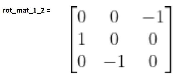
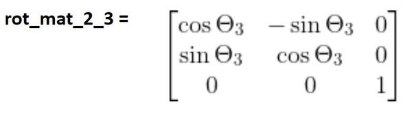
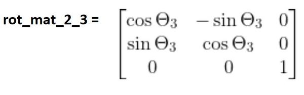
Now that we know the frame 1 equivalent to the axes in frame 2, we need to complete the derivation of the rotation matrix from frame 2 to 1 by finding the matrix that takes into account the rotation of frame 2 due to changes θ2..
θ2 is a rotation around the z1 axis and also the z2 axis. We therefore need to multiply the matrix we found above by the standard form of the z rotation matrix.
You can see that frame 3 has the same orientation as frame 2. Therefore, the same logic applies again.
Now we’re done. The three matrices above would go into your code and would enable you to flexibly convert frame 3 (end-effector frame) into frame 0, given that you know the angles of each servo motor.
rot_mat_0_3 = (rot_mat_0_1)(rot_mat_1_2)(rot_mat_2_3)
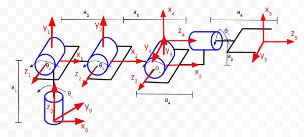
Example 4 – Six Degree of Freedom Robotic Arm
Draw the Denavit-Hartenberg Frames
Now let’s create the rotation matrices for a 6 degree of freedom robotic arm like the one pictured below.
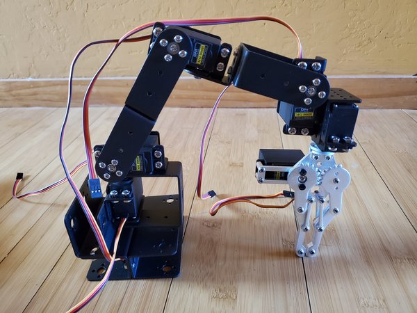
Our goal is to find a rotation matrix that can help us convert frame 5 (the point where the tip of both fingers of the robotic gripper make contact with each other) to frame 0 (the base frame). My notation for this rotation matrix is rot_mat_0_5.
rot_mat_0_5 = (rot_mat_0_1)(rot_mat_1_2)(rot_mat_2_3)(rot_mat_3_4)(rot_mat_4_5)
Let’s go through this step by step. First, let’s find rot_mat_0_1.
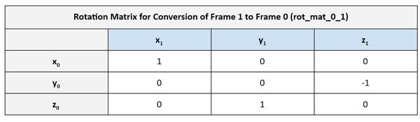
Now we have one matrix needed to calculate the rot_mat_0_1. We need to find the other now. To do that, we need to now account for rotation between the two frames. Frame 1 can rotate in response to changes in θ1. When θ1 changes, it causes rotation around the z0 axis of frame 0.
Let’s use the standard z-rotation matrix (assume rotation around the z0 axis of frame 0). We need to place that before the matrix we just found:
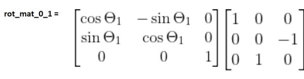
Multiplying the matrices above, together, we get:
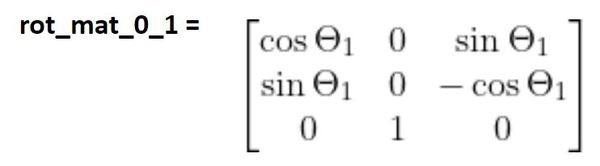
Now let’s create the rotation matrix between frame 2 and frame 1. Remember our diagram:
The first thing we need to do is to convert the x, y, and z axes of frame 2 to the x, y, and z axes of frame 1. You can see in the kinematic diagram that:
- x-axis of frame 2 is just like the x-axis of frame 1
- y-axis of frame 2 is just like the y-axis of frame 1
- z-axis of frame 2 is just like the z-axis of frame 1
Therefore, the first term we’ll use to calculate the rotation matrix from frame 2 to 1 will be the identity matrix.
Now that we know the frame 1 equivalent to the axes in frame 2, we need to complete the derivation of the rotation matrix from frame 2 to 1 by finding the matrix that takes into account the rotation of frame 2 due to changes θ2..
θ2 is a rotation around the z1 axis. z1 and the z2 axis both point the same direction. We therefore need to multiply the matrix we found above by the standard form of the z rotation matrix. We can put it before or after…it doesn’t matter in this case. Let’s put it before.
You can see that frame 3 has the same orientation as frame 2. Therefore, the same logic applies again.
Now, let’s find rot_mat_3_4.
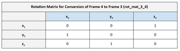
Now that we’ve projected the axes of frame 4 onto frame 3, we need to account for rotation between the axes.
Frame 4 can rotate in response to changes in θ4. When θ4 changes, it causes rotation around the z3 axis of frame 3.
Let’s use the standard z-rotation matrix (assume rotation around the z3 axis of frame 3). We need to place that before the matrix we just found:
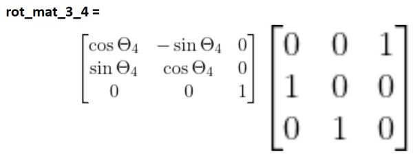
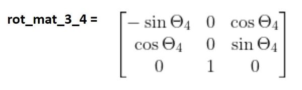
Now we multiply the matrices together:
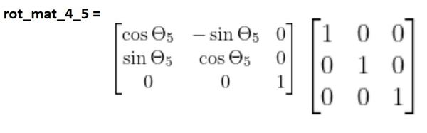
Finally, we need to convert from frame 5 to frame 4. You can see that both frames have the same orientation, so we use the identity matrix to project the axes of frame 5 on to frame 4.
Now we need to complete the derivation of the rotation matrix from frame 5 to 4 by finding the matrix that takes into account the rotation of frame 5 due to changes in θ5.
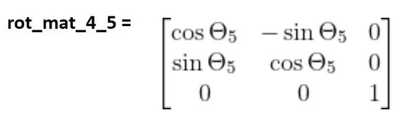
θ5 is a rotation around the z4 axis. z4 and the z5 axes both point the same direction. We therefore need to multiply the identity matrix by the standard form of the z rotation matrix.
Create the Code in Python
Here is the code. I saved the file as rotation_matrices_6dof.py.
import numpy as np # Scientific computing library

# Project: Calculating Rotation Matrices for a 6 DOF Robotic Arm
# Author: Addison Sears-Collins
# Date created: August 6, 2020

# Servo (joint) angles in degrees
servo_0_angle = 0 # Joint 1
servo_1_angle = 0 # Joint 2
servo_2_angle = 0 # Joint 3
servo_3_angle = 0 # Joint 4
servo_4_angle = 0 # Joint 5

# This servo would open and close the gripper (end-effector)
servo_5_angle = 0 # Joint 6

# Convert servo angles from degrees to radians
servo_0_angle = np.deg2rad(servo_0_angle)
servo_1_angle = np.deg2rad(servo_1_angle)
servo_2_angle = np.deg2rad(servo_2_angle)
servo_3_angle = np.deg2rad(servo_3_angle)
servo_4_angle = np.deg2rad(servo_4_angle)
servo_5_angle = np.deg2rad(servo_5_angle)

# This matrix helps convert the servo_1 frame to the servo_0 frame.
rot_mat_0_1 = np.array([[np.cos(servo_0_angle), 0, np.sin(servo_0_angle)],
                        [np.sin(servo_0_angle), 0, -np.cos(servo_0_angle)],
                        [0, 1, 0]])

# This matrix helps convert the servo_2 frame to the servo_1 frame.
rot_mat_1_2 = np.array([[np.cos(servo_1_angle), -np.sin(servo_1_angle), 0],
                        [np.sin(servo_1_angle), np.cos(servo_1_angle), 0],
                        [0, 0, 1]])

# This matrix helps convert the servo_3 frame to the servo_2 frame.
rot_mat_2_3 = np.array([[np.cos(servo_2_angle), -np.sin(servo_2_angle), 0],
                        [np.sin(servo_2_angle), np.cos(servo_2_angle), 0],
                        [0, 0, 1]])

# This matrix helps convert the servo_4 frame to the servo_3 frame.
rot_mat_3_4 = np.array([[-np.sin(servo_3_angle), 0, np.cos(servo_3_angle)],
                        [np.cos(servo_3_angle), 0, np.sin(servo_3_angle)],
                        [0, 1, 0]])

# This matrix helps convert the servo_5 frame to the servo_4 frame.
rot_mat_4_5 = np.array([[np.cos(servo_4_angle), -np.sin(servo_4_angle), 0],
                        [np.sin(servo_4_angle), np.cos(servo_4_angle), 0],
                        [0, 0, 1]])

# Calculate the rotation matrix that converts the
# end-effector frame (frame 5) to the servo_0 frame.
rot_mat_0_5 = rot_mat_0_1 @ rot_mat_1_2 @ rot_mat_2_3 @ rot_mat_3_4 @ rot_mat_4_5

# Display the rotation matrix
print(rot_mat_0_5)
Here is the output:
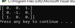
We see that the rotation matrix that converts the end-effector frame into the base frame is:
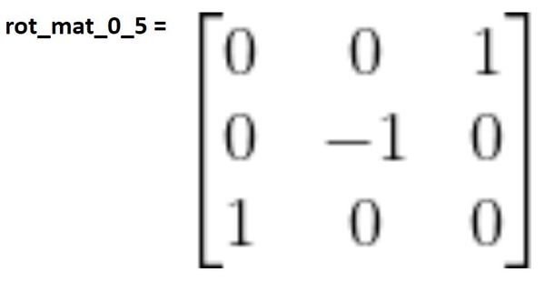
As an error check, see if the matrix above makes sense.
- Column 1 is saying that x5 and z0 point the same direction, and every other axis combination is perpendicular.
- Column 2 indicates that y5 and y0 point in the opposite direction, and every other axis combination is perpendicular.
- Column 3 indicates that z5 and x0 point the same direction, and every other axis combination is perpendicular.
You can see in the diagram below that the rotation matrix from frame 0 to frame 5 when all joint variables are 0 degrees makes sense.
Going Beyond Rotation
Up until now, we have learned how to account for changes in the orientation of reference frames in robotic manipulators. We know how to convert the orientation of the end-effector frame into the orientation of the base 0 frame. All we need to know are the angles of each servo, and we can plug those into the matrices and solve for the solution.
But rotation (i.e. orientation) is just half of the puzzle. The end-effector (i.e. paint brush, robotic gripper, robotic hand, vacuum suction cup, etc.) can change position as well as orientation. If we want to program a robot to pick up an item off a conveyor belt in a factory, we need to make sure the end-effector is oriented correctly, but we also need to make sure it goes to the right position in three-dimensional space (i.e. has the right x, y, and z coordinates).
After all, the origin (0, 0, 0) of the reference frame (i.e. x-y-z coordinate frame) for the end-effector is not located in the same position as the origin of the base frame. So in addition to the end-effector’s orientation, we also need to know its position in terms of the base frame if we want to have our robot do useful work.
We have ignored the link lengths (labeled with the letter a) and the fact that the end-effector is displaced from the base frame.
In my next post, we’ll examine how to account for this displacement.
Keep building!
References
Credit to Professor Angela Sodemann from whom I learned these important robotics fundamentals. Dr. Sodemann teaches robotics over at her website, RoboGrok.com. While she uses the PSoC in her work, I use Arduino and Raspberry Pi since I’m more comfortable with these computing platforms. Angela is an excellent teacher and does a fantastic job explaining various robotics topics over on her YouTube channel.