
In this tutorial, we’ll learn the fundamentals of assigning Denavit-Hartenberg coordinate frames (i.e. x, y, and z axes) to different types of robotic arms.
Denavit-Hartenberg (D-H) frames help us to derive the equations that enable us to control a robotic arm.
The D-H frames of a particular robotic arm can be classified as follows:
- Global coordinate frame: This coordinate frame can have many names…world frame, base frame, etc. In this two degree of freedom robotic arm, the global coordinate frame is where the robot makes contact with the dry-erase board.
- Joint frames: We need a coordinate frame for each joint.
- End-effector frame: We need a coordinate frame for the end effector of the robot (i.e. the gripper, hand, etc….that piece of the robot that has a direct effect on the world).
To draw the frames (i.e. x, y, and z axes), we follow four rules that will enable us to take a shortcut when deriving the mathematics for the robot. These rules collectively are known as the Denavit-Hartenberg Convention.
Four Rules of the Denavit-Hartenberg Convention
Here are the four rules that guide the drawing of the D-H coordinate frames:
- The z-axis is the axis of rotation for a revolute joint.
- The x-axis must be perpendicular to both the current z-axis and the previous z-axis.
- The y-axis is determined from the x-axis and z-axis by using the right-hand coordinate system.
- The x-axis must intersect the previous z-axis (rule does not apply to frame 0).
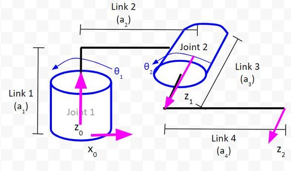
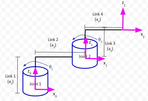
1. The z-axis is the axis of rotation for a revolute joint (like Joints 1 and 2 in the diagram below).
For example, in the diagram below, the z-axis (pink line) for Joint 1 will point straight upwards out of the servo motor. This coordinate frame is the global reference frame. It is the frame that is connected to the first joint.
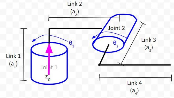
Let’s draw the second z-axis.
For our last z-axis, I have a choice. I’ll put it in the same direction as the second z-axis.
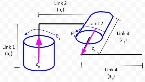
2. The x-axis must be perpendicular to both the current z-axis and the previous z-axis.
Let’s draw the x-axis for the global reference frame. We need to make sure it is perpendicular to the z0 axis. We have a choice here. I’ll go with the x-axis pointing to the right since it is easier to see on the diagram.
Let’s draw the x-axis for the Joint 2 reference frame. We need to make sure it is perpendicular to both z0 and z1.
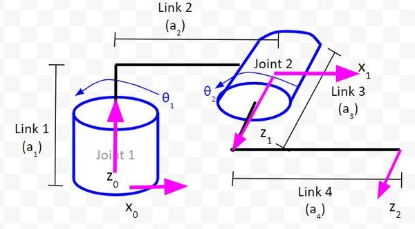
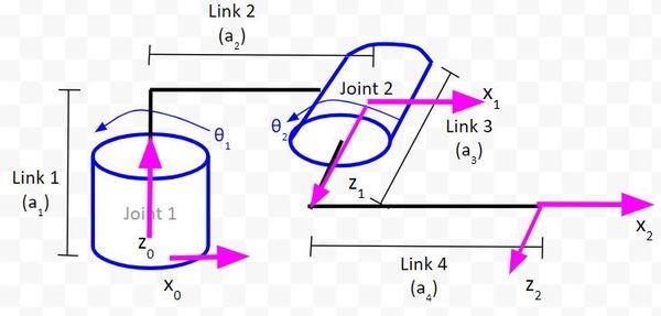
Now, let’s draw x2.
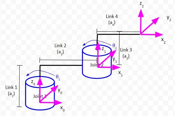
3. The y-axis is determined from the x-axis and z-axis by using the right-hand coordinate system.
For the right-hand rule, you:
- Take your right hand and point your four fingers in the direction of the x-axis.
- Point your thumb in the direction of the z-axis.
- Your palm points in the direction of the y-axis.
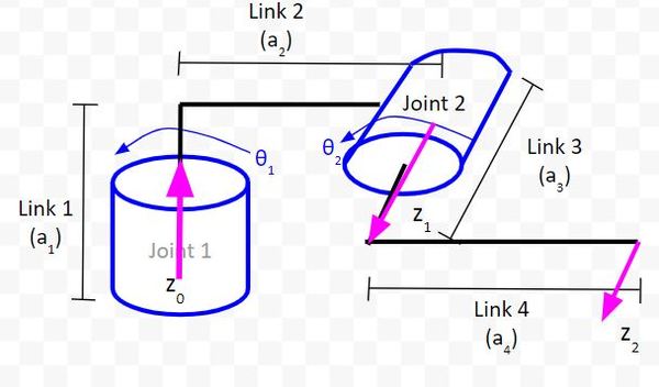
So, in this diagram below, how do we draw y0?
- x0 points to the right (point the four fingers of your right hand in that direction).
- z0 points toward the sky (point your thumb in that direction).
- Therefore, y0 points into the page.
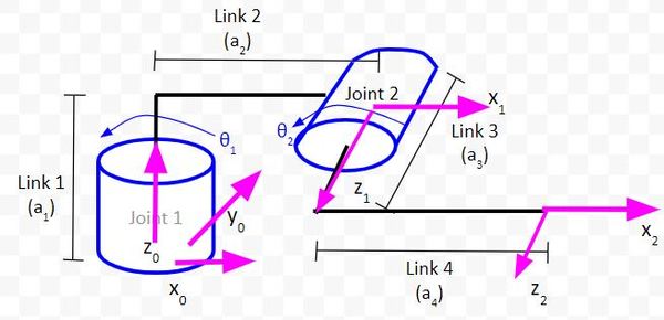
Below I have drawn the y-axis for coordinate frames 1 and 2 using the right-hand rule.
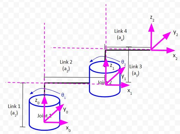
4. The x-axis must intersect the previous z-axis (rule does not apply to frame 0).
You can see from the red lines below that this rule holds for the diagram we drew.
More Practice With Denavit-Hartenberg Frames
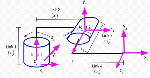
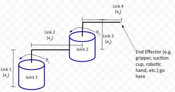
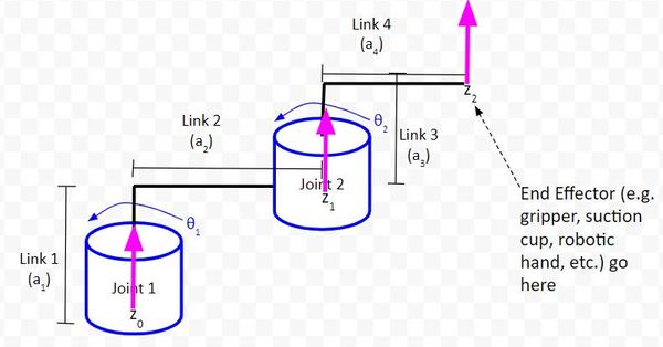
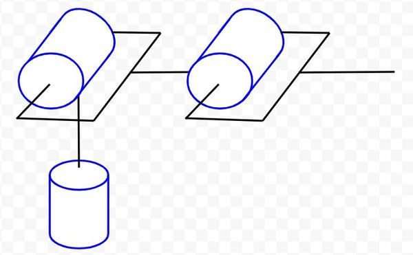
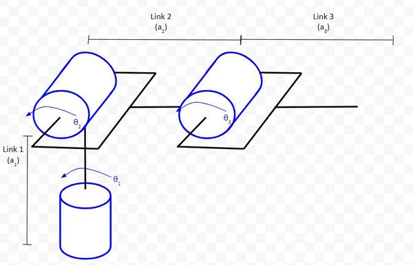
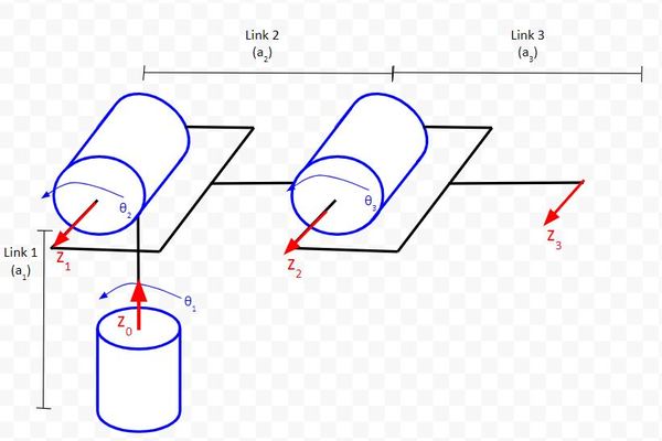
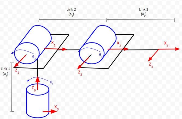
Example 1 – Two Degree of Freedom Robotic Arm
Let’s get some more practice drawing D-H frames on a kinematic diagram. We’ll use this diagram below of the two-degree of freedom robotic arm.
Remember the four rules.
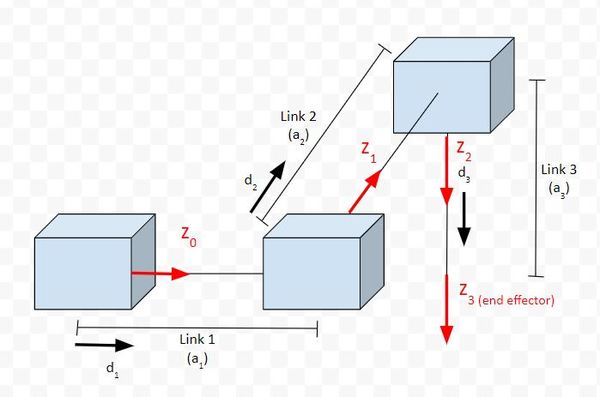
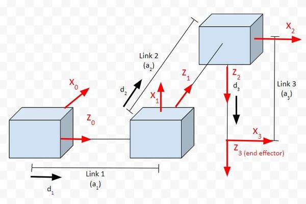
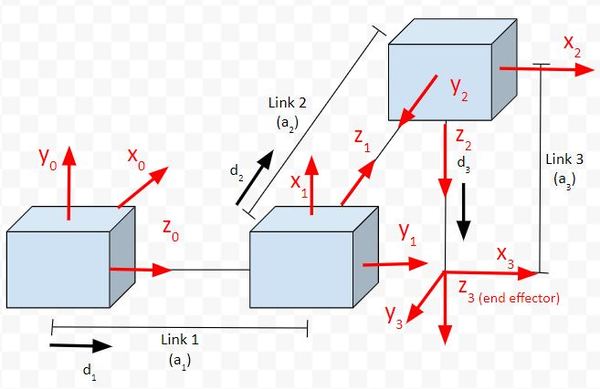
Rule #1: The z-axis is the axis of rotation for a revolute joint (like Joints 1 and 2 in the diagram below).
Rule #2: The x-axis must be perpendicular to both the current z-axis and the previous z-axis.
Rule #3: The y-axis is determined from the x-axis and z-axis by using the right-hand coordinate system.
Rule #4: The x-axis must intersect the previous z-axis (rule does not apply to frame 0).
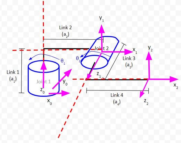
We draw a dashed line extending the x and z-axes and confirm that the axes intersect.
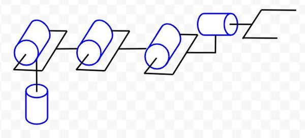
Example 2 – Cartesian Robot
Let’s do some more examples so that you get comfortable drawing kinematic diagrams.
We’ll start with the cartesian robot. You’ll often see this robot in 3D printing, laser cutting, and computer numerical control (CNC) applications.
Here is an example of a cartesian robot.
A cartesian robot is made up of three prismatic joints, that correspond to the x, y, and z axes. These joints are perpendicular to each other.
Whereas a revolute joint produces rotational motion, a prismatic joint produces linear (i.e. sliding) motion along a single axis. In a real application, a prismatic joint is a linear actuator. This type of actuator can be purchased at any online store that sells electronics equipment (e.g. Amazon, eBay, etc.).
Let’s draw the kinematic diagram for a cartesian robot.
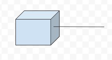
Here is our first joint:
Let’s add our second and third joint.
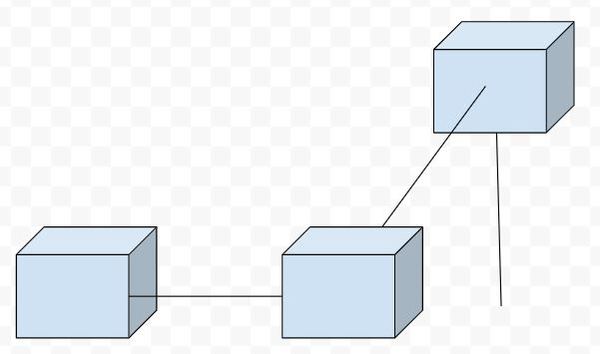
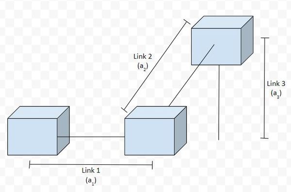
Now, let’s label the links. When drawing the kinematic diagram for prismatic joints, we assume that each joint is not extended.
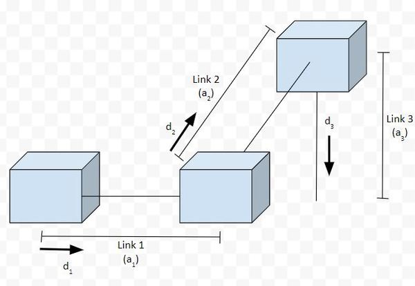
Let’s draw in arrows to show the direction of motion (we’ll use the letter d to represent the direction of motion from a 0 position of the linear actuator…i.e. prismatic joint).
Let’s draw the axes.
Rule #1: For a prismatic joint, the z-axis has to be the direction of motion.
Rule #2: The x-axis must be perpendicular to both the current z-axis and the previous z-axis.
Rule #3: The y-axis is determined from the x-axis and z-axis by using the right-hand coordinate system.
You stick your fingers in the direction of x. Your thumb goes in the direction of z. Your palm faces the direction of y.
Rule #4: The x-axis must intersect the previous z-axis (rule does not apply to frame 0).
Check each frame to see if this rule holds. You extend the z-axes and see if they intersect the next x axis. You’ll find that Rule 4 will be followed for all frames.
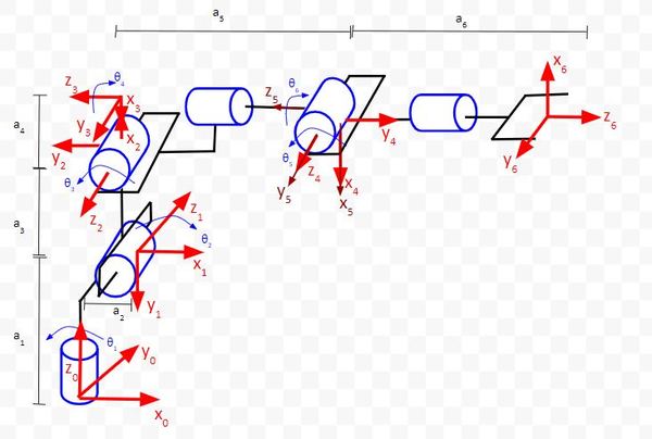
Example 3 – Articulated Robot
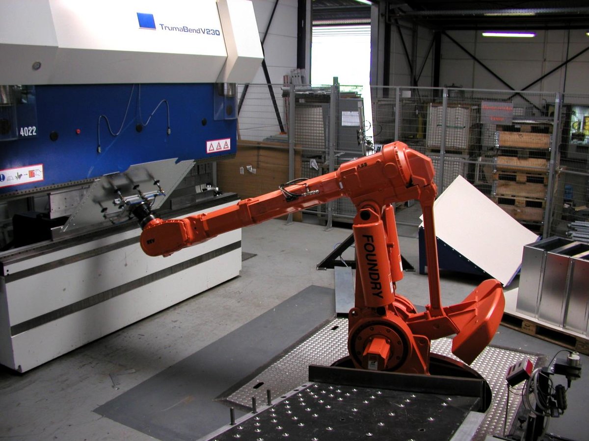
Articulated robots are your standard robot arms. They are the most common types of robots you will find in factories. This type of robot is the one that is most similar to the human arm.
Here is an example of an articulated robot.
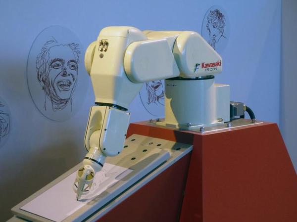
Articulated robots come in all shapes and sizes. Some of these types of robots can be pretty strong. If you go inside a car factory, you’ll see giant articulated robots lifting cars and trucks with ease.
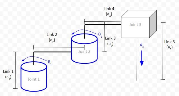
Let’s draw the kinematic diagram for a three degree of freedom articulated robot. This robot is similar to an old robot named the Stanford Arm. The difference is that, in this robot diagram, we will make the third joint a revolute joint instead of a prismatic joint.
Let’s label the links (we’ll use the letter a to represent link lengths) and draw the direction of positive rotation.
Now, let’s go through the four rules.
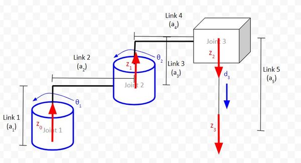
Rule #1: The z-axis is the axis of rotation for a revolute joint (like Joints 0 and 1 in the diagram below).
For the end effector in the image above, I made the z-axis the same direction as the frame before it since it will make the math easier.
Rule #2: The x-axis must be perpendicular to both the current z-axis and the previous z-axis.
Note that, for the base frame, we can set the x-axis to be anything we want as long as rule #2 holds. I’ve made it go to the right in the diagram below.
For drawing the other x axes, you have a choice of which direction you want to make them. I like to look ahead to rule #4 (Rule #4: The x-axis must intersect the previous z-axis) to help with this decision.
Rule #3: The y-axis is determined from the x-axis and z-axis by using the right-hand coordinate system.
You stick your fingers in the direction of x. Your thumb goes in the direction of z. Your palm faces the direction of y.
Rule #4: The x-axis must intersect the previous z-axis (rule does not apply to frame 0).
Check each frame to see if this rule holds. You extend the z-axes and see if they intersect the next x axis. You’ll find that Rule 4 will be followed for all frames.
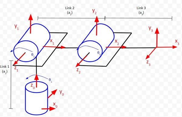
Example 4 – SCARA Robot
Let’s see how to draw the kinematic diagram for the SCARA robot.
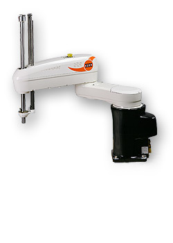
Here is an example of the SCARA robot:
The SCARA robot is commonly used for pick and place (i.e. moving a part from one point to another) and small assembly applications.
Rule #1: The z-axis is the axis of rotation for a revolute joint. For a prismatic joint, the z-axis has to be the direction of motion.
Rule #2: The x-axis must be perpendicular to both the current z-axis and the previous z-axis.
Rule #3: The y-axis is determined from the x-axis and z-axis by using the right-hand coordinate system.
Rule #4: The x-axis must intersect the previous z-axis (rule does not apply to frame 0).
Check each frame to see if this rule holds. You extend the z-axes and see if they intersect the next x axis. You’ll find that Rule 4 will be followed for all frames.
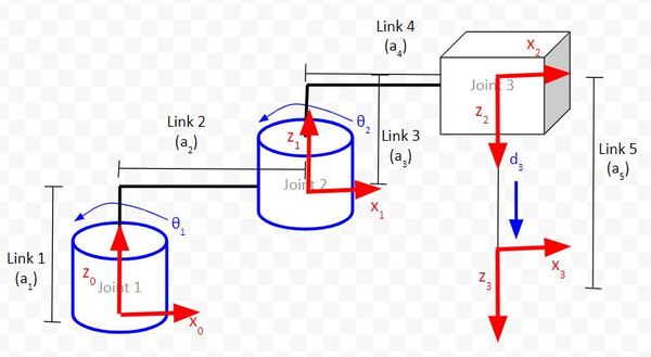
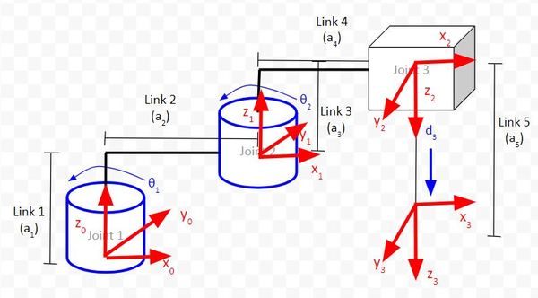
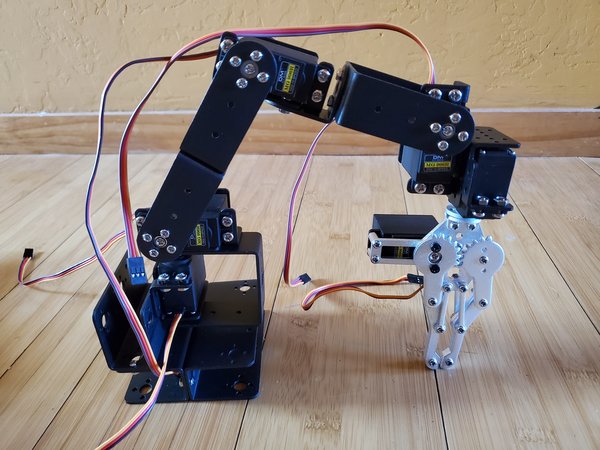
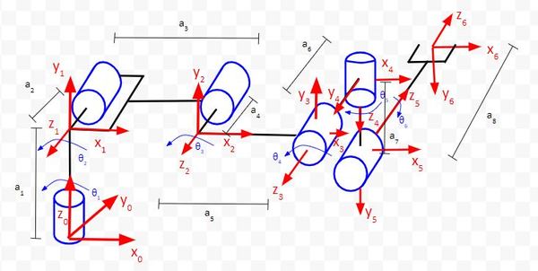
Example 5 – Six Degree of Freedom Robotic Arm
Now, let’s draw the kinematic diagram and D-H frames for a 6 degree of freedom robotic arm like the one below.
Note that the 6th servo is located on the gripper. I won’t include that joint in the analysis since it is not part of the main arm of the robot.
We start by drawing the kinematic diagram. Remember that, in a kinematic diagram, we assume that all servos are at 0 degrees (i.e. all joint variables are 0). Therefore, for some servos, we’ll have to make the assumption that the angle range of the servo is from -90 to 90 degrees as opposed to the normal 0 to 180 degree range so that we have a valid kinematic diagram.
Let’s label the links and draw the direction of positive rotation.
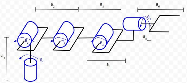
Now, let’s go through the four rules.
Rule #1: The z-axis is the axis of rotation for a revolute joint.
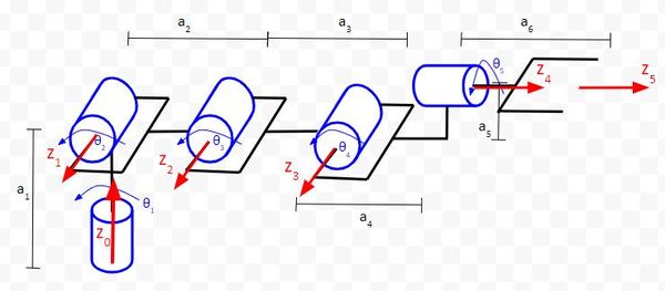
Rule #2: The x-axis must be perpendicular to both the current z-axis and the previous z-axis.
Up until now, we have always placed the origin of a coordinate frame at the center of the joint. However, doing this is not required. We can place the frame origin wherever we want.
Notice in the diagram below that we have to move the origin of frame 4 backwards, by a distance of a4 in order to satisfy Rule #2.
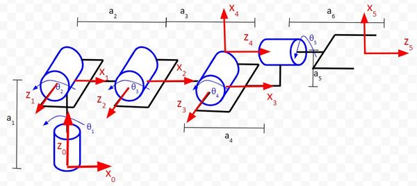
Rule #3: The y-axis is determined from the x-axis and z-axis by using the right-hand coordinate system.
You stick your fingers in the direction of x. Your thumb goes in the direction of z. Your palm faces the direction of y.
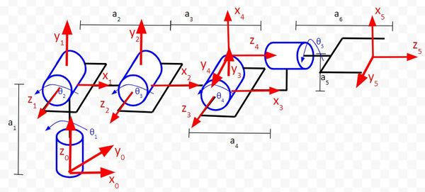
Rule #4: The x-axis must intersect the previous z-axis.
If you go frame by frame in the diagram above, you can see that the rule holds.
Example 6 – Six Degree of Freedom Collaborative Robot
Let’s draw the kinematic diagram for a six degree of freedom robot like the Universal Robots UR5. At the end of this robotic arm, you would typically have some sort of end effector like a hand, gripper, or suction cup.
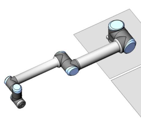
The kinematic diagram will be drawn with the robotic arm in a flat orientation, parallel to a table, for example.
Remember the four rules:
- The z-axis is the axis of rotation for a revolute joint.
- The x-axis must be perpendicular to both the current z-axis and the previous z-axis.
- The y-axis is determined from the x-axis and z-axis by using the right-hand coordinate system.
- The x-axis must intersect the previous z-axis (rule does not apply to frame 0).
We can see in the diagram that all the rules hold.
Example 7 – Six Degree of Freedom Industrial Robot
Let’s draw the kinematic diagram for a six degree of freedom industrial robot like the FANUC LRMate 200iD.
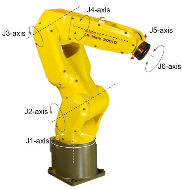
Go through each of the four rules. Here is what I drew:
Keep building!
References
Credit to Professor Angela Sodemann for teaching me this stuff. Dr. Sodemann is an excellent teacher (She runs a course on RoboGrok.com). On her YouTube channel, she provides some of the clearest explanations on robotics fundamentals you’ll ever hear.