
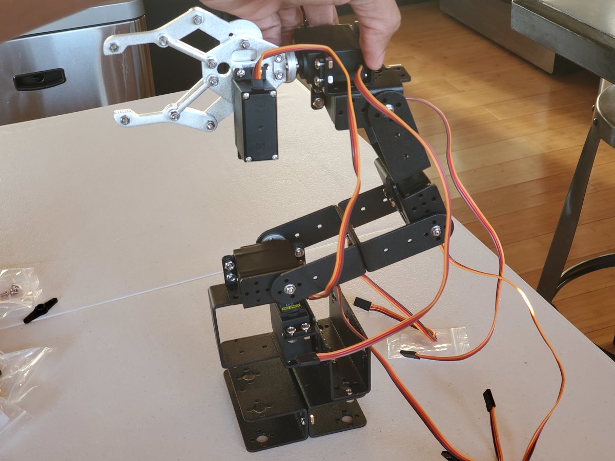
In this tutorial, we will build a robotic arm with six degrees of freedom from scratch. A degree of freedom is the number of variables needed to fully describe the position and orientation of a system (e.g. x, y, z, and rotation about each of those axes in the case of our robotic arm).
Our goal is to build an early prototype of a product to make it easier and faster for factories, warehouses, and food processing plants to pick up objects and place them into boxes (i.e. pick and place).
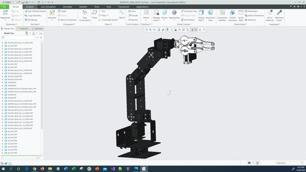
I modeled the robot in a CAD (Computer-aided design) program called Creo Parametric. Here are the STL files.
Real-World Applications
Robotic arm systems have a number of real-world applications. Here are just a few examples:
- Warehouses and Logistics
- Grocery Stores
- Hospitals and Medical Centers
- Military
- Food Processing Plants
- And more…
Let’s get started!
Prerequisites
- No prior knowledge necessary. We’ll build everything from the ground up.
You Will Need
This section is the complete list of components you will need for this project.
- 6DOF Robotic Arm Kit with MG996R Servos (Robotic arm)
- Phillips Screwdriver
- 7/32 Wrench
- 9/32 Wrench
- Needle-nose Pliers
- Wire cutters
- 1 Male-to-Female, Female-to-Female, and Male-to-Male Jumper Wires Kit
- 1 6-Channel Digital Servo Tester
- 4xAA Battery Holder with On Off Switch
- 4 AA Batteries
- 1 x DC Adjustable Power Supply Capable of 30V/10A (You could also use a 4 x AA Battery Holder With Wires or a 6V, 2800mAh, NiMH Battery Pack. Just be aware that these batteries will drain really quickly).
Directions
Let’s assemble the robotic arm. Follow the steps carefully, and take your time to make sure everything is set up properly. It took me almost a week to assemble the arm. Go slowly.
The instructions for assembling the arm come inside the package, but let’s walk through the process anyways.
Unpack the Robotic Arm Kit
Open the robotic arm kit. Lay out all the components on a table. You should have the following pieces of hardware:
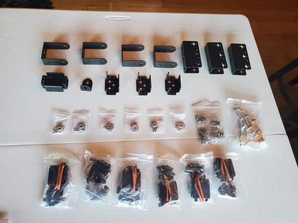
- 1 x Aluminum Clamp Claw
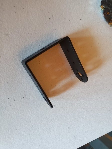
- 1 x L-type Servo Bracket
- 3 x U-type Robot Waist Bracket
- 4 x Long U-type Servo Bracket
- 4 x Miniature Ball Radial Bearing
- 5 x Multi-functional Servo Bracket
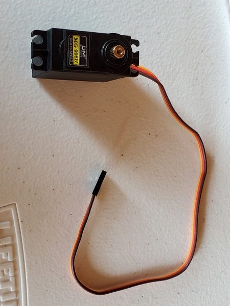
- 6 x MG996R Servo
- 6 Sets x Aluminum Servo Horns
- 4 Sets x Round Head M3*10 Screws and M3 Nuts (The 10 means 10mm in length, including the head)
- 20 Sets x Round Head M3*8 Screws and M3 Nuts
- 24 Sets x Fixed Head M4*10 Screws and M4 Nuts (I never used these)
- 30 Sets x Round Head M3*6 Screws and M3 Nuts
- *Note: The kit that I have didn’t have labels on the screws, making it tricky to figure out what screws to use at what stage. Just use screws and nuts that can fit into the hole when the time comes. Don’t sweat over the exact type of screw I mention in this tutorial. The end goal is to make sure every part is secure.
Assemble the Base
Grab 6 x M3*8 screws and nuts (these are the screws that are 8mm long from the top of the head to the base of the screw)..
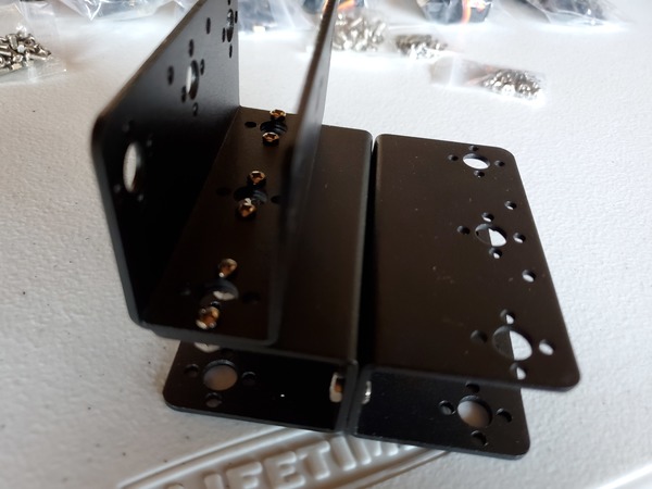
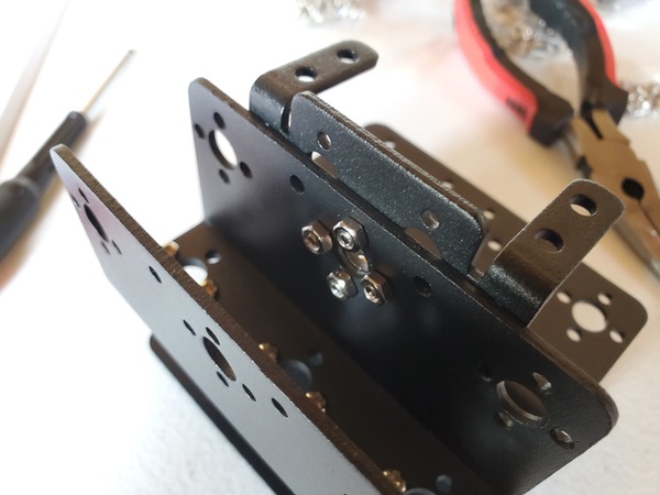
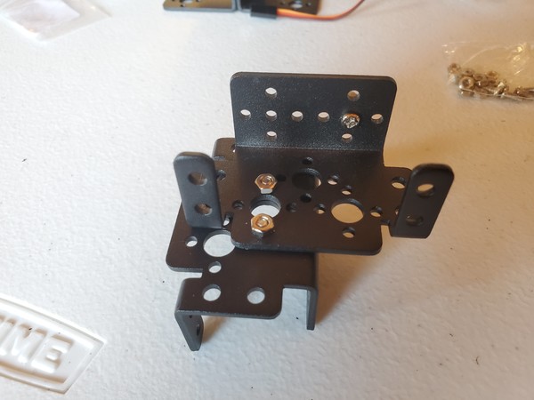
Using a screwdriver (helpful to use needle-nose pliers to hold the nut in place as you screw in the screws and nuts), connect two of the U-type robot waist brackets together using the M3*8 screws and nuts.
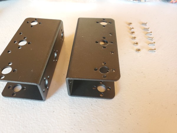
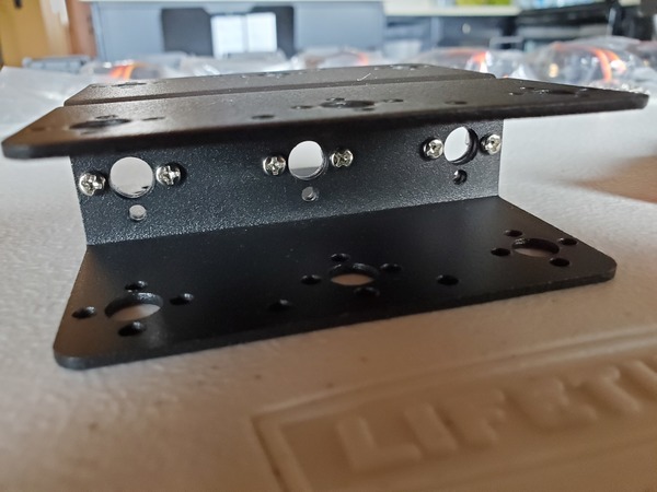
Grab the third U-type robot bracket, and attach it to one side of the base using six M3*8 screws and nuts.
Install the First Servo Motor
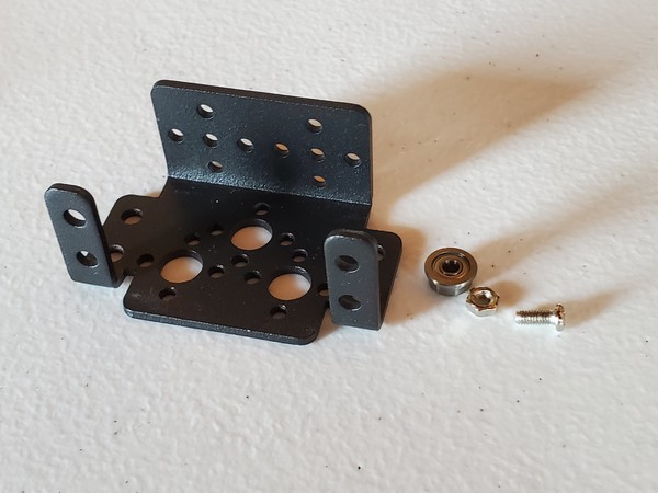
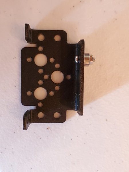
Grab one M3*10 screw, nut, and a bearing.
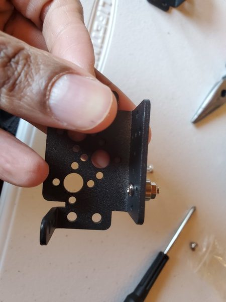
Grab one Multi-functional servo bracket.
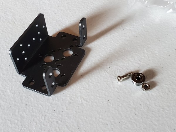
Place a screw through the hole. It might have a bit of trouble fitting through the hole, so make sure you apply enough force to snap it through there.
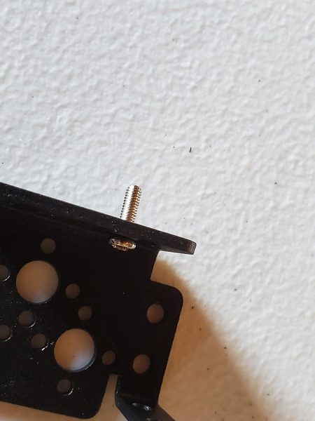
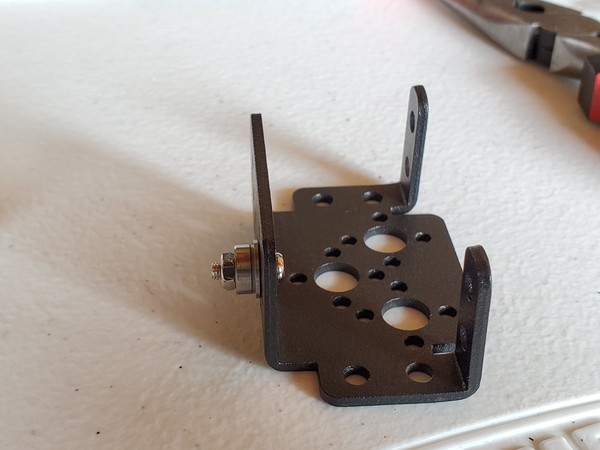
Insert the bearing over the screw, with the wide end of the bearing touching the Multi-functional servo bracket.
Insert the nut over the screw in order to hold the bearing in place.
Tighten the screw with a 7/32 inch wrench.
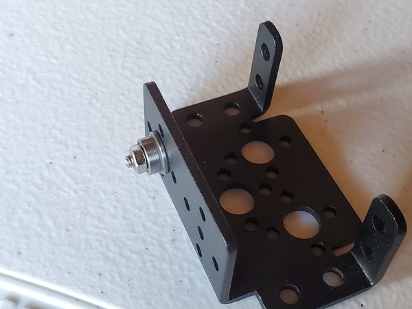
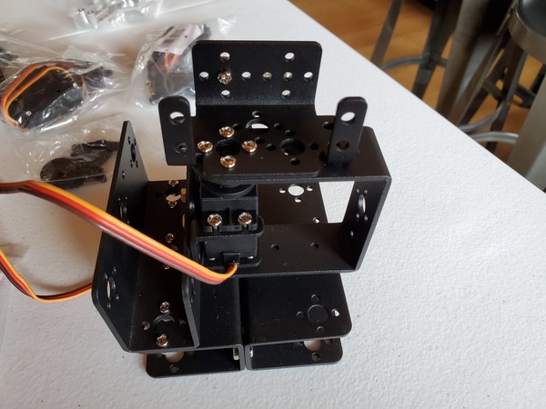
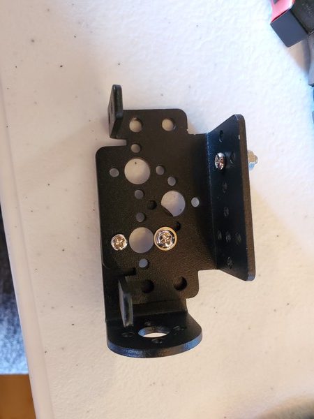
Now we need to attach the Multi-functional servo bracket to that U-type bracket that was mounted on top of the robot base. Use four M3*6 screws and nuts to do this job.
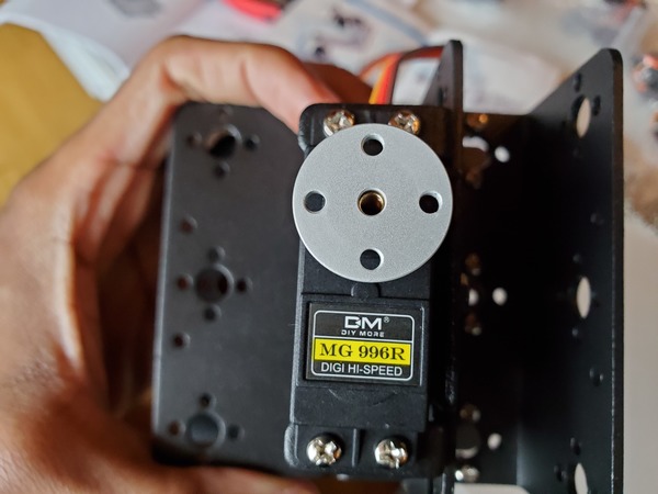
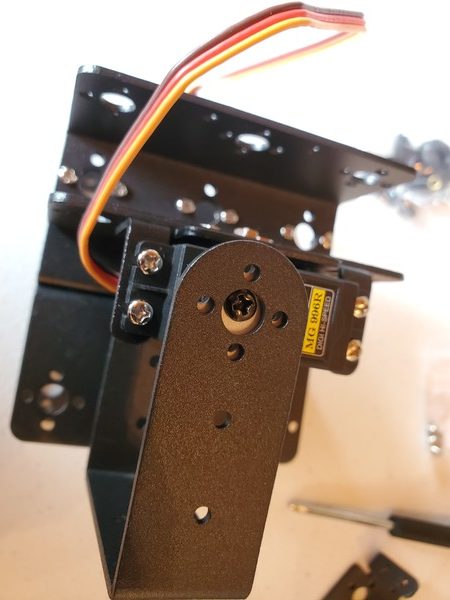
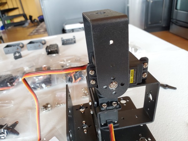
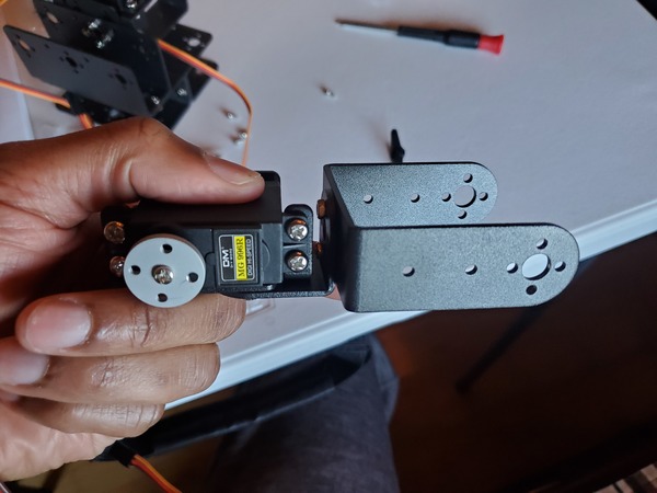
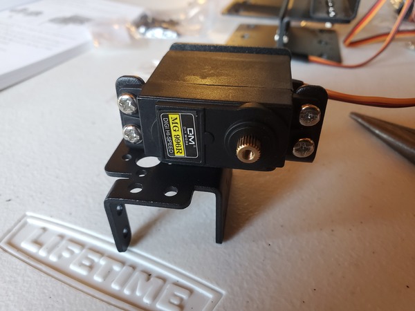
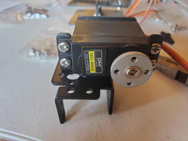
Take one of your servo motors outside of its bag.
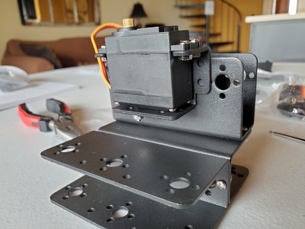
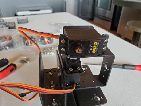
Mount it over the two arms of the Multi-functional servo bracket. Make sure the motor is mounted just as you see it here. We will call this servo motor the steering servo.
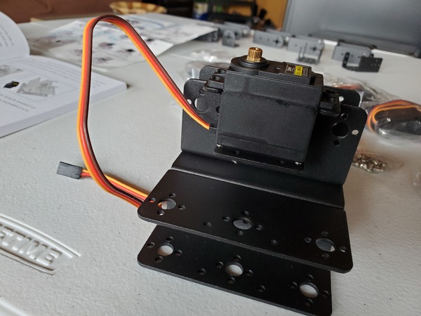
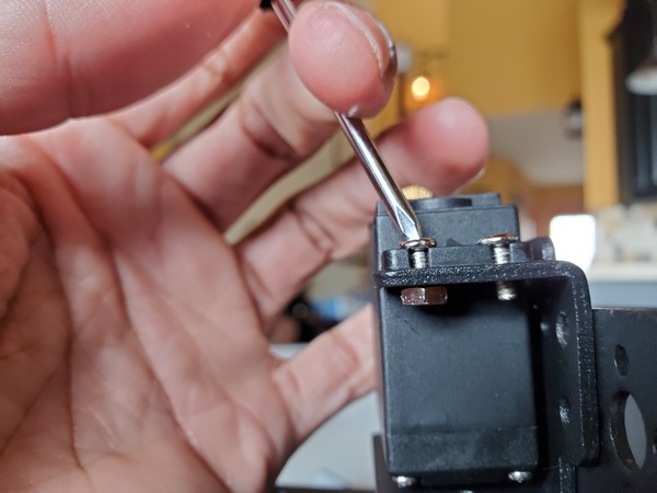
Get four M3*8 screws and nuts (the fattest screws and nuts in the kit). Use these to secure the steering servo into place.
I recommend holding the nut in place with one of your fingers or the needle-nose pliers and using a Phillips screwdriver to tighten the screw inside the nut.
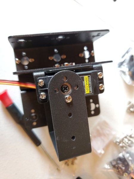
Here is how your setup should look at this stage.
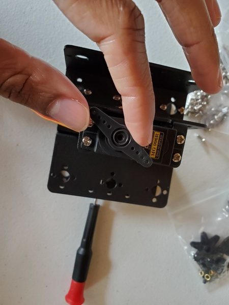
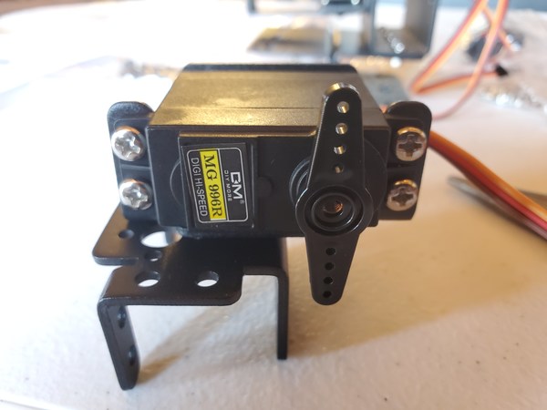
Grab one of the plastic rocker arms. It should be inside the bag that had your servo motor.
Insert the rocker arm on top of the steering servo. The grooves of the steering servo should fit nicely with the grooves of the rocker arm.
The rocker arm should be placed perpendicular across the steering servo axis (i.e. that golden, grooved metal circle on top of the steering servo).
Now take your finger and move the rocker arm to the left and to the right.
Take note of where the rocker stops turning when you twist the rocker arm to the left side with your fingers.
Now take note of where the rocker arm stops turning on the right side.
Reposition the rocker arm so that it is perpendicular across the steering servo when the underlying steering servo axis is exactly at the halfway point between the left and right stopping points that you just marked.
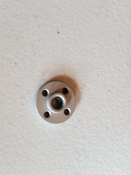
After you have adjusted the angle of the steering servo axis using the rocker arm, grab the servo horn.
Carefully remove the rocker arm by pulling it straight up off the steering servo axis. You want to be careful not to move the steering servo axis.
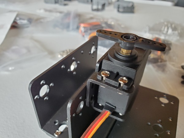
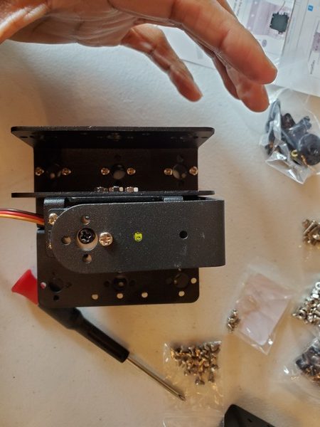
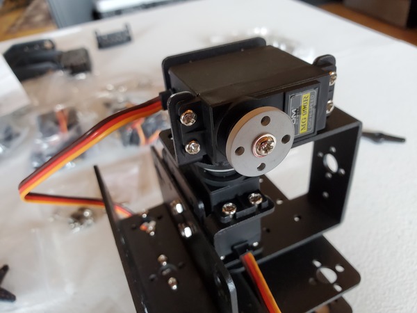
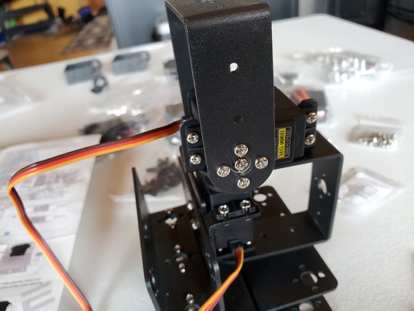
Fit the servo horn on top of the steering servo axis so that it looks like this. One of the holes of the servo horn should point straight forward.
Twist the servo horn from right to left. The rotation range should be 0-225°.
Once you are sure that the servo horn is positioned properly over the steering servo axis, secure it into place by placing a screw in the center.
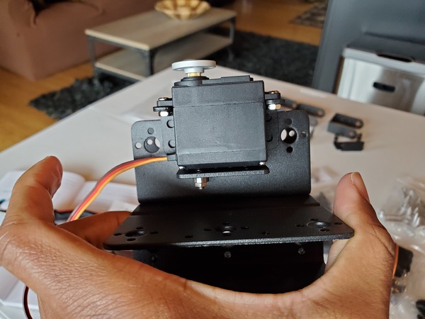
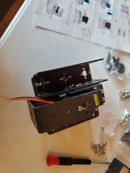
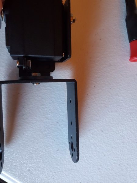
Grab one of the long U-type brackets.
Slip the hole of the U-type bracket over the bearing underneath the servo motor.
Slip the other end of the U-type bracket over the top of the servo motor. The big hole of the U-type bracket should be over the screw.
Grab a small screw.
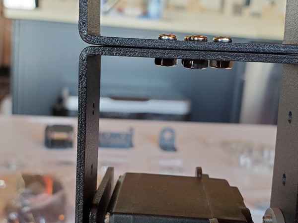
Place the screw in one of the small holes of the long U-type bracket. Don’t tighten too hard at this stage.
Move the U-type bracket from left to right. Make sure it can touch each side of that third U-type robot waist bracket.
Now, remove the screw you just put in.
Install the Second Servo Motor
Grab a bearing, a long screw, and a nut.
Grab a Multi-functional servo bracket.
Secure the bearing on the Multi-functional servo bracket using the screw and the nut.
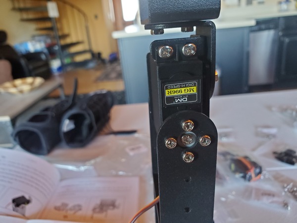
Grab four M3*6 screws.
Use the screws to secure the Multi-functional servo bracket on top of the long U-type servo bracket.
Grab another servo. This servo will be called the arm servo since it is responsible for raising and lowering the robotic arm.
Place it into the Multi-functional servo bracket.
Secure the servo into place with four fat screws (M3*8) and nuts. I recommend using needle-nose pliers to hold the nut steady while you use a Phillips screwdriver to tighten the screw.
Grab one of the plastic rocker arms. It should be inside the bag that had your servo motor.
Insert the rocker arm on top of the steering servo. The grooves of the steering servo should fit nicely with the grooves of the rocker arm.
The rocker arm should be placed perpendicular across the steering servo axis (i.e. that golden, grooved metal circle on top of the steering servo).
Now take your finger and move the rocker arm to the left and to the right.
Take note of where the rocker stops turning when you twist the rocker arm to the left side with your fingers.
Now take note of where the rocker arm stops turning on the right side.
Reposition the rocker arm so that it is perpendicular across the steering servo when the underlying steering servo axis is exactly at the halfway point between the left and right stopping points that you just marked.
After you have adjusted the angle of the steering servo axis using the rocker arm, grab the servo horn.
Carefully remove the rocker arm by pulling it straight up off the steering servo axis. You want to be careful not to move the steering servo axis.
Fit the servo horn on top of the steering servo axis so that it looks like this. One of the holes of the servo horn should point straight forward.
Twist the servo horn from right to left. The rotation range should be 0-225°.
Once you are sure that the servo horn is positioned properly over the steering servo axis, secure it into place by placing a screw in the center.
Grab one of the long U-type brackets.
Slip the hole of the U-type bracket over the bearing on one side of the Multi-functional bracket.
Slip the other end of the U-type bracket over the top of the servo motor. The big hole of the U-type bracket should be over the screw.
Grab four M3*6 screws.
Place the four screws over the small holes of the long U-type bracket.
Move the U-type bracket from left to right. Make sure it has a full range of motion. It should hit the first U-type bracket when you twist it to the right. That is fine.
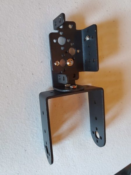
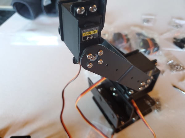
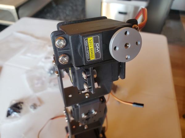
Now, we are going to attach a long U-type servo bracket to the U-type bracket you just secured.
Grab a long U-type servo bracket and four M3*6 screws and nuts.
Your robotic arm should have a full range of motion, backward and forwards.
Install the Elbow
Now, we need to install the elbow.
Grab the L-type servo bracket, a Mult-functional servo bracket, a bearing, an M3*10 screw, and a nut.
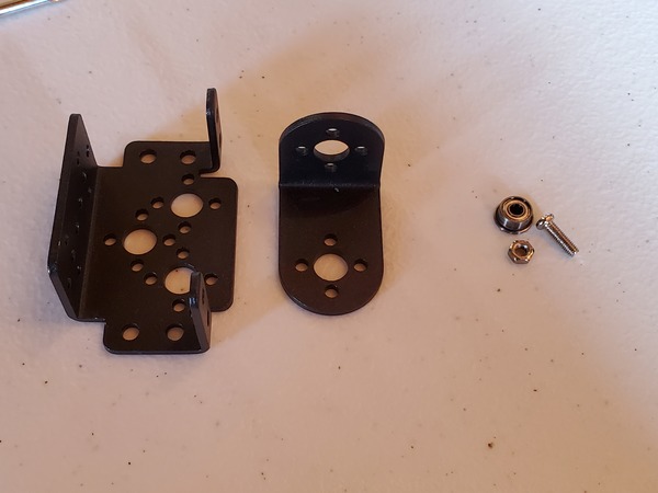
Attach the bearing to the Multi-functional servo bracket using the M3*10 screw and nut.
Grab two M3*6 screws and nuts. If you’ve run out of M3*6 screws, just use screws and nuts in the kit that are able to fit through the holes. Sometimes the kits don’t have all the screws you need, and it doesn’t help that the kit that I received came with unlabeled screws.
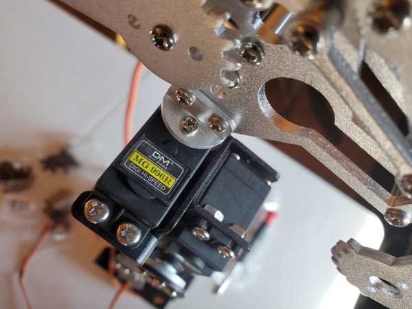
Attach the L-type servo bracket to the Mult-functional servo bracket as shown in the image below. Use the two screws and nuts.
Grab the last long U-type bracket.
Use two M3*6 screws and nuts to secure the U-type bracket to the L-type bracket.
Grab a servo motor.
Place the servo motor into the Mult-functional servo bracket.
Secure the servo motor into the Multi-functional servo bracket with four M3*8 screws and nuts. Again, don’t worry if you don’t have enough M3*8 screws and nuts. The goal is to use screws and nuts to secure the servo motor into the holder.
Grab one of the plastic rocker arms. It should be inside the bag that had your servo motor.
Insert the rocker arm on top of the steering servo. The grooves of the steering servo should fit nicely with the grooves of the rocker arm.
Now take note of where the rocker arm stops turning on the right side.
Reposition the rocker arm so that it is perpendicular across the steering servo when the underlying steering servo axis is exactly at the halfway point between the left and right stopping points that you just marked.
After you have adjusted the angle of the steering servo axis using the rocker arm, grab the servo horn.
Carefully remove the rocker arm by pulling it straight up off the steering servo axis. You want to be careful not to move the steering servo axis.
Fit the servo horn on top of the steering servo axis so that it looks like this.
Twist the servo horn from right to left. The rotation range should be 0-225°.
Once you are sure that the servo horn is positioned properly over the steering servo axis, secure it into place by placing a screw in the center.
Place the Multi-functional servo bracket (with attached servo motor) inside the top U-bracket.
Secure it into place with four screws.
Install the Wrist
Grab two Multi-functional brackets.
Get a bearing, a screw, and a nut. Attach them to one of the Multi-functional brackets.
Grab two M3*6 screws and nuts. Use these screws and nuts to connect the Multi-functional brackets together.
Grab a servo motor, and place it into one of the Multi-functional brackets.
Grab four M3*8 screws and secure the servo motor into place.
Grab the arm rudder and place it over the servo axis.
As we have done with other servo motors, the arm rudder should be straight up and down at the halfway point of the motion of the servo (when you twist to the left and right).
Once you are happy with the angle, take the arm rudder off, and replace it with a servo horn.
Stick a screw in the middle of the servo horn to tighten it.
Place the Mult-functional bracket in the U-type bracket.
Use the servo horn screws to secure the servo horn into place.
Install the Hand Servo
Grab another servo motor.
Place the servo motor into the Multi-functional bracket up top.
Secure the servo motor into the Multi-functional bracket using four screws and nuts.
Add the arm rudder on top of the servo axis, and do the same routing we have done before to find the halfway point. You want the arm rudder to be up and down across the servo motor at the halfway point.
Attach the Claw
Grab a screw and place it in the center of the hand servo horn.
Grab two screws and secure the claw to the hand servo horn.
Grab the last servo and four M3*6 screws.
Attach the last servo to the claw using the screws. If you run out of screws, feel free to pull some screws from the base of the robot.
Grab the arm rudder and place it on top of the servo axis.
Find the halfway point of the servo axis. When you find the halfway point place the arm rudder on top of the axis so that it points straight up and down.
Carefully take the arm rudder off.
Push the servo horn over the servo axis.
Use a small screw to secure the servo horn on the servo axis. The screw that you should use is the one with something that looks like a disk or a washer around the neck near the head. Don’t tighten it too tight.
Arrange the claw in the open position.
Grab two small black screws.
Secure the loose piece of the claw to the servo horn using the two black screws.
Check that you’re able to open and close the claw. The claw should close completely.
That’s it. If you’ve gotten this far, you have assembled the body of your robotic arm.
Move the Robotic Arm
Your robotic arm has six motors (six degrees of freedom). To move your robotic arm, you can buy a six-channel digital servo tester (you can find them on eBay or AliExpress) and move them like I explain on this post.
All you need to do is connect your digital servo tester to a power source (i.e. 6V…which can be a 4xAA battery pack), and also connect your servos to the tester. You’ll be up and running in just a few minutes.