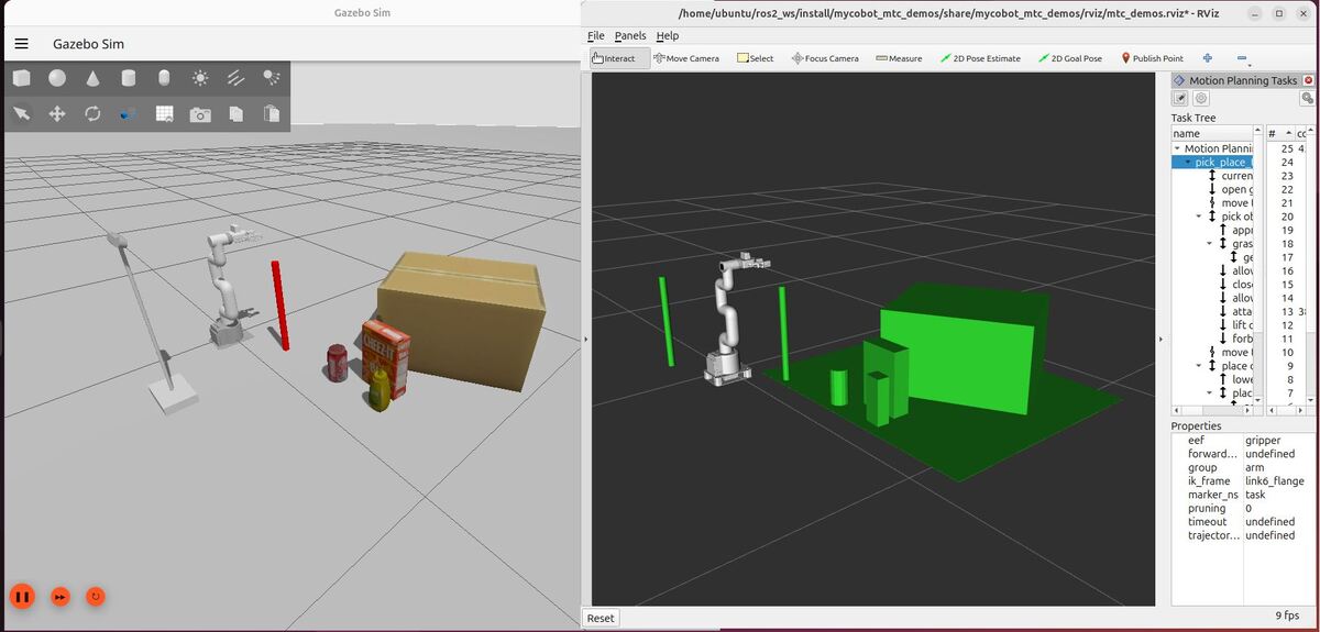
In this tutorial, we’ll learn how to use Docker to make working with ROS 2 projects easier and more reliable.
When developing robotics software, setting up your environment can be frustrating—installing ROS 2, managing dependencies, and making sure everything works the same on different computers. Docker solves this by creating containers—lightweight, isolated environments that include everything your ROS 2 project needs to run.
A Docker container contains:
- ROS 2 (and any version you choose)
- All necessary dependencies and libraries
- Your project files and code
Because everything is bundled together, Docker containers make sure your project runs the same way, whether on your laptop, a robot, or a cloud server. No more “it works on my machine” issues!
In this tutorial, I’ll guide you step by step—from understanding Docker basics to creating custom containers for ROS 2 projects. You’ll also learn how to handle more advanced setups like running multiple containers and using graphical tools such as RViz.
By the end, you’ll know how to use Docker to build more portable, consistent, and manageable robotics environments. Let’s get started!
Prerequisites
You have completed this tutorial: Pick and Place Using MoveIt 2 and Perception – ROS 2 Lyrical.
What is a Docker Container?
Think of a Docker container as a lightweight, standalone, and executable package that includes everything needed to run a piece of software, including the code, runtime, system tools, libraries, and settings.
Here’s an analogy to help understand Docker:
Imagine you’re moving to a new house. Instead of packing all your belongings into random boxes, you pack each room into its own shipping container. Each container has everything that room needs to function – furniture, appliances, decor, even the right temperature and humidity settings. When you arrive at your new house, you can unload each container, and each room is instantly set up exactly as it was, regardless of what the new house is like.
In the same way, Docker containers package up not just your application, but also all its dependencies, configurations, and even the operating system it needs. This containerized application can then run on any computer that has Docker installed, regardless of that computer’s specific setup.
Key benefits of Docker for ROS 2 development include:
- Consistency: Your ROS 2 application will run the same way on any machine with Docker, eliminating “it works on my machine” problems.
- Isolation: Each container runs in its own environment, preventing conflicts between different projects or versions of ROS 2.
- Portability: You can share your entire ROS 2 setup with others or deploy it to different machines.
- Version Control: You can manage different versions of ROS 2 or your application in separate containers.
- Resource Efficiency: Containers are more lightweight than traditional virtual machines, using fewer system resources.
About Docker Images
Docker images are the foundation of containerization, serving as blueprints for creating containers. Think of a Docker image as a recipe for a gourmet meal. Just as a recipe contains all the ingredients and instructions needed to prepare a dish, a Docker image includes all the components and instructions required to run a specific application or environment.
A Docker image is a snapshot of a Docker container, capturing the application code, runtime, libraries, environment variables, and configuration files. When you’re working with ROS 2, your image might start with a base that includes the ROS 2 framework, then add your own robotics code and any additional dependencies on top.
Docker images are read-only, meaning once created, they don’t change. If you need to make modifications, you create a new image, much like creating a new version of a recipe. This immutability ensures consistency across different environments, from development to production.
Images can be shared with others through registries like Docker Hub, similar to how you might share a favorite recipe with friends.
Exploring Public ROS 2 Docker Images
Docker Hub is the official repository for Docker images, serving as a central location where developers can find, share, and download pre-built Docker images. For ROS 2 developers, it’s the go-to place to find official ROS 2 Docker images maintained by the ROS community.
On Docker Hub, you can find a wide variety of ROS 2 images for different distributions and configurations. The official ROS 2 images are hosted under the “ros” repository. To explore these images, you can visit this page.
At that page, you’ll see a list of available ROS 2 images with different tags. These tags represent various ROS 2 distributions and configurations. For example, you might see tags like:
- lyrical
- lyrical-ros-core
- lyrical-perception
- lyrical-ros-base
The page features a “Filter Tags” search bar, which is useful for finding specific ROS 2 distributions or configurations.
For example, if you’re looking for Lyrical-specific images, you can type “lyrical” in the search bar to filter the results.
Each image tag provides information about the operating system it supports, potential vulnerabilities, and the compressed size of the image. This information helps you choose the right image for your project and system requirements.
Later in this tutorial, I will show you how we pull an image from here automatically using what is called a Dockerfile.
Install Docker
Let’s go ahead and install Docker.
I will walk you through the entire process, but you can use this page as a reference.
Uninstall Old Versions of Docker
The first thing you need to do is to uninstall any outdated versions of Docker that might be lurking on your computer.
Open a terminal window, and type the following command:
for pkg in docker.io docker-doc docker-compose docker-compose-v2 podman-docker containerd runc; do sudo apt-get remove $pkg; doneYou might get a message back saying that you have none of those packages installed. That is just fine.
Set Up the Apt Repository
Run these commands in order:
sudo apt-get update
sudo apt-get install ca-certificates curl
sudo install -m 0755 -d /etc/apt/keyrings
sudo curl -fsSL https://download.docker.com/linux/ubuntu/gpg -o /etc/apt/keyrings/docker.asc
sudo chmod a+r /etc/apt/keyrings/docker.asc
Add the repository to Apt sources:
echo \
  "deb [arch=$(dpkg --print-architecture) signed-by=/etc/apt/keyrings/docker.asc] https://download.docker.com/linux/ubuntu \
  $(. /etc/os-release && echo "$VERSION_CODENAME") stable" | \
  sudo tee /etc/apt/sources.list.d/docker.list > /dev/null
sudo apt-get updateInstall Docker
sudo apt-get install docker-ce docker-ce-cli containerd.io docker-buildx-plugin docker-compose-pluginVerify that Docker Installed
sudo docker run hello-world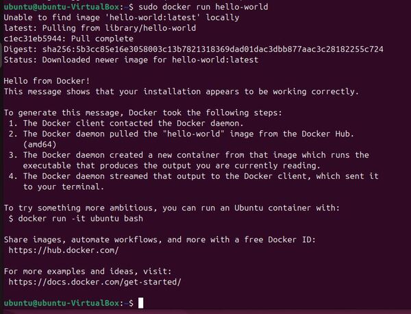
Post-Installation Configuration
Here are some recommended steps to take after you have successfully installed Docker.
Create the docker group. On Ubuntu 26.04 the installer usually makes this group for you already, so do not worry if you get back “group ‘docker’ already exists”. That message is fine and you can carry straight on to the next command.
sudo groupadd dockerAdd your user to the docker group.
sudo usermod -aG docker $USERReboot your computer.
sudo rebootOr you could have activated changes to groups instead of rebooting:
newgrp dockerTo test that you can run Docker without using “sudo”, type the following command:
docker run hello-world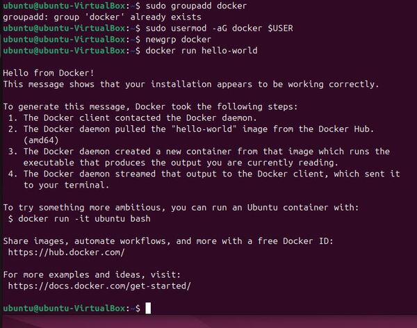
Now configure Docker to start on boot:
sudo systemctl enable docker.servicesudo systemctl enable containerd.serviceYou can stop this startup on boot at any time, by typing:
sudo systemctl disable docker.servicesudo systemctl disable containerd.serviceNow you’re all set.
Create an entrypoint.sh
After successfully installing Docker on your system, the next step is to create an entrypoint.sh script. This script is important for setting up the proper environment inside your Docker container.
The entrypoint.sh script is the first script that runs when your Docker container starts. It is responsible for setting up the ROS 2 environment, ensuring all necessary variables are set, and preparing your workspace. Let’s create this script in your project directory.
Create a new folder called docker.
cd ~/ros2_ws/src/mycobot_ros2mkdir -p docker && cd dockerCreate a new script.
touch entrypoint.shSave the file, and close it.
This script performs several important tasks:
- It sets up important environment variables.
- It manages the ROS_DOMAIN_ID, which is important for multi-robot communication.
- It sources the necessary ROS 2 setup files.
- It builds your ROS 2 workspace using colcon.
After creating the file, make it executable by running:
chmod +x ~/ros2_ws/src/mycobot_ros2/docker/entrypoint.shThis entrypoint.sh script will be used in your Dockerfile, which we’ll create in the next steps. It ensures that every time you start a container based on your image, the ROS 2 environment is properly configured and ready for development.
Create a workspace.sh
After setting up our entrypoint.sh, the next step is to create a workspace.sh script. This script is responsible for setting up our ROS 2 workspace inside the Docker container, including installing any third-party packages we might need for our robotics project.
Let’s create this script in the same directory as our entrypoint.sh.
Open a terminal window.
cd ~/ros2_ws/src/mycobot_ros2/dockertouch workspace.sh Copy the this content into the file.
Save the file, and close it.
This script does the following:
- Sources the ROS 2 setup file to ensure we’re working in a ROS 2 environment.
- Navigates to the src directory of our ROS 2 workspace.
- Clones third-party packages.
- Installs all ROS 2 dependencies for the newly added packages.
- Builds the workspace using colcon.
After creating the file, make it executable by running:
chmod +x ~/ros2_ws/src/mycobot_ros2/docker/workspace.shThis workspace.sh script will be used in your Dockerfile to set up your ROS 2 workspace during the image build process. It allows you to add or remove packages from your workspace by modifying this script, ensuring that your Docker image contains all the necessary packages for your robotics project.
Two things in this script got shorter on Lyrical. The MoveIt Task Constructor used to be cloned from GitHub and patched by hand. It is a regular package now, so the script just installs it and the patching is gone. The MongoDB step is gone too. It was only there for a database feature none of these tutorials use, and the library it needed is no longer on Ubuntu 26.04.
Create a build.sh File
After setting up our entrypoint.sh and workspace.sh scripts, the next step is to create a build.sh file. This script automates the process of building our Docker image and setting up necessary directories on the host system. Let’s create this script in the same directory as our previous scripts.
Open a terminal window.
cd ~/ros2_ws/src/mycobot_ros2/dockertouch build.sh Copy this content into the file:
#!/bin/bash

# Get the absolute path of the directory containing this script (docker directory)
SCRIPT_PATH=$(dirname $(realpath "$0"))

# Get the parent directory path (mycobot_ros2 directory)
# This is where our actual ROS 2 package code lives
PARENT_PATH=$(dirname "$SCRIPT_PATH")

# Function to build the Docker image
# This function handles the actual Docker build process
build_docker_image()
{
    # Set a log message for the build process
    LOG="Building Docker image manipulation:latest ..."

    # Print the log message using our debug function
    print_debug

    # Build the Docker image
    # -f $SCRIPT_PATH/Dockerfile: Specify the path to the Dockerfile in the docker directory
    # -t manipulation:latest: Tag the image as manipulation:latest
    # $PARENT_PATH: Use the parent directory as the build context, allowing access to all package files
    # --no-cache: Build the image without using the cache, ensuring fresh dependencies
    sudo docker image build -f $SCRIPT_PATH/Dockerfile -t manipulation:latest $PARENT_PATH --no-cache
}

# Function to create a shared folder
# This folder will be used to share files between the host and the Docker container
create_shared_folder()
{
    # Check if the directory doesn't exist
    if [ ! -d "$HOME/automaticaddison/shared/ros2" ]; then
        # Set a log message for folder creation
        LOG="Creating $HOME/automaticaddison/shared/ros2 ..."

        # Print the log message
        print_debug

        # Create the directory and its parent directories if they don't exist
        # -p flag creates parent directories as needed
        mkdir -p $HOME/automaticaddison/shared/ros2
    fi
}

# Function to print debug messages
# This provides consistent formatting for our log messages
print_debug()
{
    # Print an empty line for readability
    echo ""

    # Print the log message
    echo $LOG

    # Print another empty line for readability
    echo ""
}

# Main execution flow

# First, create the shared folder that will be mounted in the container
create_shared_folder

# Then, build the Docker image
build_docker_image
Save the file, and close it.
This script does the following:
- Determines the script’s directory path.
- Defines a function to build the Docker image using the Dockerfile in the same directory.
- Defines a function to create a shared folder on the host system.
- Executes the functions to create the shared folder and build the Docker image.
After creating the file, make it executable by running:
chmod +x ~/ros2_ws/src/mycobot_ros2/docker/build.shThis build.sh script serves several important purposes:
- It automates the Docker image building process, ensuring consistency each time you build.
- It creates a shared folder on your host system, which can be used to exchange files between your host and the Docker container.
- It uses the –no-cache option when building the Docker image, ensuring that you always get the latest versions of packages and dependencies.
This will create the necessary shared folder and build your Docker image based on the Dockerfile we’ll create in the next steps. The script provides a convenient way to rebuild your image whenever you make changes to your Dockerfile or other configuration files.
Create a bash_aliases.txt
After setting up our build scripts, it’s helpful to create a bash_alias.txt file. This file will contain useful aliases that can simplify common tasks in our ROS 2 development workflow. Aliases are shorthand commands that can represent longer, more complex commands.
Let’s create this file now.
cd ~/ros2_ws/src/mycobot_ros2/dockertouch bash_aliases.txtCopy this content into the file:
# Aliases for the ~/.bashrc file
alias build='cd ~/ros2_ws/ && colcon build && source ~/.bashrc'
alias cleanup='echo "Cleaning up..." && \
sleep 5.0 && \
pkill -9 -f "ros2|gazebo|gz|nav2|amcl|bt_navigator|nav_to_pose|rviz2|assisted_teleop|cmd_vel_relay|robot_state_publisher|joint_state_publisher|move_to_free|mqtt|autodock|cliff_detection|moveit|move_group|basic_navigator"'
alias elephant='ros2 launch mycobot_description robot_state_publisher.launch.py'
alias moveit='bash ~/ros2_ws/src/mycobot_ros2/mycobot_bringup/scripts/mycobot_280_gazebo_and_moveit.sh'
alias mtc_demos='bash ~/ros2_ws/src/mycobot_ros2/mycobot_bringup/scripts/mycobot_280_mtc_demos.sh'
alias pick='bash ~/ros2_ws/src/mycobot_ros2/mycobot_mtc_pick_place_demo/scripts/robot.sh'
alias pointcloud='bash ~/ros2_ws/src/mycobot_ros2/mycobot_mtc_pick_place_demo/scripts/pointcloud.sh'
alias robot='bash ~/ros2_ws/src/mycobot_ros2/mycobot_bringup/scripts/mycobot_280_gazebo.sh'
Save the file, and close it.
To use these aliases in your Docker container, you’ll need to include this file in your Docker image and source it in the .bashrc file. We’ll cover how to do this when we create the Dockerfile in a future step.
Create a docker-compose.yml File
After setting up our build scripts and aliases, the next step is to create a docker-compose.yml file. This file defines how Docker should run our containers, allowing us to manage multi-container applications.
Let’s create this file now.
cd ~/ros2_ws/src/mycobot_ros2/dockertouch docker-compose.ymlAdd this code.
Save the file, and close.
This docker-compose.yml file does several important things:
- It defines a service named ‘manipulation’ based on our Docker image.
- It sets up the container to use the host’s network and IPC namespace.
- It grants the container privileged access, which is often necessary for robotics applications.
- It sets up environment variables and volume mappings for GUI applications and file sharing.
- It includes commented-out examples of how to set up multiple containers for different ROS 2 nodes.
Write a Dockerfile From Scratch
After setting up our support files, the next important step is to create our Dockerfile. This file contains instructions for building our Docker image, which will serve as the environment for our ROS 2 development.
Create a new file named Dockerfile.
cd ~/ros2_ws/src/mycobot_ros2/dockertouch DockerfileAdd this content.
# Set the ROS distribution as an argument, defaulting to 'lyrical'
ARG ROS_DISTRO=lyrical

# The base image comes from the official ROS repository hosted on Docker Hub
# You can find available ROS images here: https://hub.docker.com/_/ros/tags
# We're using the ros-base image which includes core ROS 2 packages
FROM ros:${ROS_DISTRO}-ros-base

# Set the maintainer information for this Dockerfile
LABEL maintainer="AutomaticAddison<automatic_addison@todo.com>"

# Set environment variables
ENV PIP_BREAK_SYSTEM_PACKAGES=1
ENV DEBIAN_FRONTEND=noninteractive

# Set the default shell to bash for RUN commands
# This ensures all RUN commands use bash instead of sh
SHELL ["/bin/bash", "-c"]

# Update the system and install essential tools
# This step upgrades all packages and installs utilities needed for development
RUN apt-get update -q && \
    apt-get upgrade -yq && \
    apt-get install -yq --no-install-recommends apt-utils wget curl git build-essential \
    vim sudo lsb-release locales bash-completion tzdata gosu gedit htop nano libserial-dev

# Install additional tools required for ROS 2 development
# These packages help with building and managing ROS 2 workspaces
RUN apt-get update -q && \
    apt-get install -y gnupg2 iputils-ping usbutils \
    python3-argcomplete python3-colcon-common-extensions python3-networkx python3-pip python3-rosdep python3-vcstool

# Set up the ROS 2 environment
# This ensures that ROS 2 commands are available in the shell
# rosdep is a tool for installing system dependencies for ROS packages
RUN rosdep update && \
    grep -F "source /opt/ros/${ROS_DISTRO}/setup.bash" /root/.bashrc || echo "source /opt/ros/${ROS_DISTRO}/setup.bash" >> /root/.bashrc && \
    grep -F "source /usr/share/colcon_argcomplete/hook/colcon-argcomplete.bash" /root/.bashrc || echo "source /usr/share/colcon_argcomplete/hook/colcon-argcomplete.bash" >> /root/.bashrc

# Install additional ROS 2 packages
RUN apt-get update && \
    apt-get install -y \
    ros-${ROS_DISTRO}-joint-state-publisher-gui \
    ros-${ROS_DISTRO}-xacro \
    ros-${ROS_DISTRO}-demo-nodes-cpp \
    ros-${ROS_DISTRO}-demo-nodes-py \
    ros-${ROS_DISTRO}-rviz2 \
    ros-${ROS_DISTRO}-rqt-reconfigure

# Install Mesa graphics drivers
# Mesa is an open-source implementation of OpenGL and other graphics APIs
# It's crucial for 3D rendering in many applications, including RViz in ROS
RUN apt-get update && \
    apt-get install -y software-properties-common && \
    DEBIAN_FRONTEND=noninteractive add-apt-repository ppa:kisak/kisak-mesa

# Create necessary directories
RUN mkdir -p /etc/udev/rules.d && \
    mkdir -p /root/ros2_ws/src/mycobot_ros2

# Copy the entire project into the container
# Since we're using the parent directory as context, we can copy everything
COPY . /root/ros2_ws/src/mycobot_ros2

# Copy configuration files from docker directory
# Note the docker/ prefix since we're in the parent context
COPY docker/workspace.sh /root/
COPY docker/entrypoint.sh /root/
COPY docker/bash_aliases.txt /root/.bashrc_aliases

# Make scripts executable
RUN chmod +x /root/workspace.sh /root/entrypoint.sh

# Add custom bash aliases
RUN cat /root/.bashrc_aliases >> /root/.bashrc

# Run the workspace setup script
# This typically installs workspace dependencies and builds the ROS 2 packages
WORKDIR /root
RUN ./workspace.sh

# Ensure the ROS 2 workspace is sourced in every new shell
RUN echo "source /root/ros2_ws/install/setup.bash" >> /root/.bashrc

# Set the entrypoint for the container
# This script will be run every time the container starts
ENTRYPOINT ["/root/entrypoint.sh"]

# Set the default command
# This keeps the container running indefinitely, allowing you to exec into it
CMD ["/bin/bash", "-c", "tail -f /dev/null"]
Save the file, and close.
This Dockerfile does several important things:
- It starts from a base ROS 2 image, allowing you to specify the ROS distribution.
- It installs necessary system packages and ROS 2 tools.
- It sets up the ROS 2 environment and installs additional ROS 2 packages.
- It copies your workspace files into the container.
- It runs the workspace.sh script to set up your ROS 2 workspace.
- It sets up the entrypoint script to run when the container starts.
Building a Docker Image
Now that we have our Dockerfile and supporting scripts ready, it’s time to build our Docker image. We’ll use the build.sh script we created earlier to automate this process.
To build the Docker image, follow these steps…
Open a terminal window.
Navigate to the directory containing your build.sh script:
cd ~/ros2_ws/src/mycobot_ros2/dockerRun the build script:
bash build.shWhen you run this command, the script will perform the following actions:
- Create the shared folder ~/automaticaddison/shared/ros2 if it doesn’t already exist.
- Build the Docker image using the Dockerfile in the current directory.
- Tag the image as manipulation:latest.
The build process may take several minutes, depending on your internet connection and computer speed. You’ll see output in the terminal as Docker executes each instruction in the Dockerfile.
Once the build process is complete, you can verify that your image was created successfully by running:
docker imagesYou should see an entry for manipulation:latest in the list of images.
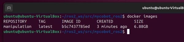
If you encounter any errors during the build process, check the error messages in the terminal output. Common issues include network problems, insufficient disk space, or syntax errors in the Dockerfile.
Keep an eye on your system storage to make sure you have enough memory for the Docker image:
df -hIf you run out of storage, you can type:
docker system pruneRemember, you can re-run the build.sh script whenever you make changes to your Dockerfile or want to ensure you have the latest versions of all packages in your image.
Useful Commands
You don’t need to run these commands. This is just for your future reference.
If at any stage you want to remove the image you just created, type:
docker rmi manipulation:latestTo remove unused images, you would type:
docker image pruneTo remove all images, you would do this:
docker image prune -aYou can also free up space on your computer using this command (I run this command regularly):
docker system pruneTo inspect an image’s details:
docker image inspect manipulation:latestTo view the history of an image’s layers:
docker history manipulation:latestTo save an image as an archive:
docker save manipulation:latest > manipulation.tarTo load an image from a tar archive:
docker load < manipulation.tarCreating and Running a Docker Container
After building our Docker image, the next step is to create and run a container from it. This process brings our ROS 2 environment to life, allowing us to interact with it and run our robotics applications.
Here’s how to create and run a Docker container using our newly built image.
Ensure you’re in the directory containing the docker-compose.yml file:
cd ~/ros2_ws/src/mycobot_ros2/dockerStart the container using Docker Compose:
docker compose up -d manipulationHere are some useful commands (you don’t need to run these now)…
To run all services:
docker compose up -dTo run specific services:
docker compose up -d manipulation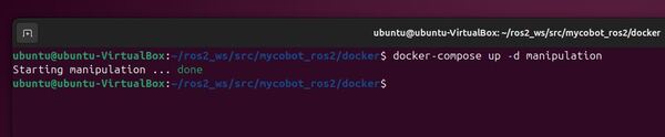
After starting your container using docker-compose, it’s a good practice to check if it is running as expected. Here’s how you can do that:
docker container ps -aThis command is particularly useful as it shows all containers, regardless of their state (running, stopped, or exited). It helps you verify that your containers were created successfully, even if they’ve stopped for some reason.
The output will look something like this:

This output shows:
- The container ID
- The image used to create the container
- The command running in the container
- When it was created
- Its current status
- Any mapped ports
- The container name
If you see your container listed with a status of “Up”, it means it is running correctly. If you see a different status or don’t see your container at all, you may need to troubleshoot your docker-compose setup or container configuration.
Remember, you can always use docker-compose logs to check for any error messages if your container is not running as expected.
To view the logs of a specific service:
docker compose logs -f manipulationRunning ROS 2 Nodes Inside a Docker Container
Now let’s go inside the manipulation container and see if we can run an arbitrary command:
Type the following command in the host machine to enable the GUI (we will need this later for RViz):
xhost + 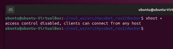
docker compose exec manipulation bashThis opens a bash shell in the ‘manipulation’ container.
Let’s open another instance of this container.
Open a new terminal window, and type:
docker compose exec manipulation bashLet’s check out the robotic arm description. Type:
elephantYou could also type:
ros2 launch mycobot_description robot_state_publisher.launch.py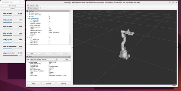
To stop the program:
Press CTRL + C to stop the nodes.
You will be unable to run anything with Gazebo due to the limited memory of our machine, but you can see that we can run RViz with no issues since it is much more lightweight.
Now let’s test how we can share files between the Docker container and the host computer.
Inside your Docker container, type this:
echo "Hello from Docker" > /root/shared/ros2/text.txtOn your host machine, check the contents of the file:
cat ~/automaticaddison/shared/ros2/text.txtYou should see the message “Hello from Docker”.

To exit the container shells, type:
exitTo stop the manipulation container:
docker compose stop manipulationThis command preserves the container and its state, allowing you to quickly start it again later without recreating everything from scratch.
If you want to start the container again later, you type:
docker compose up -d manipulationThen to get back into the container, type:
docker compose exec manipulation bashCreating Separate Docker Containers That Communicate With Each Other Using docker-compose.yaml
Now let’s run multiple Docker containers and see how they communicate with each other.
First, open the docker-compose.yml file in a text editor:
gedit docker-compose.ymlUncomment the ‘minimal_publisher’ and ‘minimal_subscriber’ services in the docker-compose.yml file. It should look like this:
services:
  manipulation: &manipulation
    container_name: manipulation
    image: manipulation:latest
    ipc: host
    network_mode: host
    privileged: true
    environment:
      - DISPLAY
      - XAUTHORITY=/tmp/.Xauthority
    volumes:
      - $HOME/automaticaddison/shared/ros2:/root/shared/ros2
      - $HOME/.Xauthority:/tmp/.Xauthority
      - /tmp/.X11-unix:/tmp/.X11-unix:rw
      - /dev:/dev
    command: ["tail", "-f", "/dev/null"]

  # The following services are commented out for this tutorial.
  # They demonstrate how to create multiple containers from the same Docker image,
  # each running a specific ROS 2 node. These containers can communicate with each other
  # because they share the same ROS_DOMAIN_ID.
  # Publisher service: Runs the demo talker node
  minimal_publisher:
    <<: *manipulation  # This uses all the same settings as the 'manipulation' service
    container_name: minimal_publisher
    command: ["ros2", "run", "demo_nodes_cpp", "talker"]

  # Subscriber service: Runs the demo listener node
  minimal_subscriber:
    <<: *manipulation  # This uses all the same settings as the 'manipulation' service
    container_name: minimal_subscriber
    command: ["ros2", "run", "demo_nodes_cpp", "listener"]
Save and exit the text editor.
Now, start all the containers:
docker compose up -dTo verify that all containers are running:
docker ps -aYou should see three containers: manipulation, minimal_publisher, and minimal_subscriber.
Now, let’s enter the manipulation container to observe the ROS 2 system:
docker compose exec manipulation bashInside the container, check the active ROS 2 nodes:
ros2 node listYou should see output similar to:
/listener
/talker
Next, check the active ROS 2 topics:
ros2 topic listYou should see output including:
/chatter
/parameter_events
/rosout
To see the messages being published, you can use:
ros2 topic echo /chatter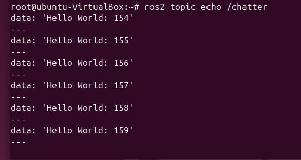
This will show the messages being published by the publisher node and received by the subscriber node.
To exit the topic echo, press CTRL + C.
To see the number of publishers and subscribers on the /chatter topic, type:
ros2 topic info /chatter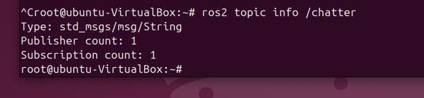
Exit the container:
exitWhen you’re done, stop all the containers:
docker compose stopThis demonstration shows how multiple Docker containers can run different ROS 2 nodes and communicate with each other. The publisher and subscriber nodes are running in separate containers but can still interact through ROS 2 topics, thanks to the shared network configuration in the docker-compose.yml file.
This setup is useful for distributed robotics applications, allowing you to isolate different components of your system while maintaining communication between them.
You can for example have one container that runs only the LIDAR and another that is dedicated to publishing GPS data.
If you ever want to remove the manipulation container, you can type:
docker container rm manipulationIf you want to remove a container that is running you need to -f (force) flag:
docker container rm -f manipulationThat’s it! Keep building!