

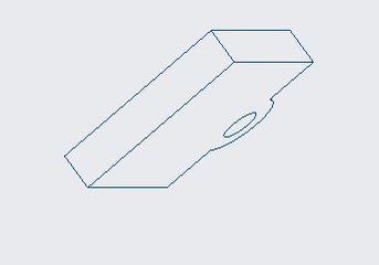
If you’re an absolute beginner to Creo Parametric, this tutorial is your guide. We’ll go step-by-step through the most common functions you’ll use again and again as you work with Creo Parametric for your design work. By the end of this tutorial, you’ll know how to create the animated part below.
Creo Parametric is a powerful 3D modeling CAD software program that is used by engineers all over the world. Without further ado, let’s get started!
Table of Contents
- Prerequisites
- How to Sketch a Rectangle in 2D
- How to Sketch a Circle in 2D
- How to Delete a Segment
- How to Create a Hole
- How to Create a New Part in 3D Using Extrude
- How to Create Additional Parts
- How to Modify an Extruded Part
- How to Create an Assembly
- How to Create Drawing Views
- How to Annotate Dimensions on a Drawing
- How to Export a Drawing as a PDF File
- How to Use Mechanisms
Prerequisites
How to Sketch a Rectangle in 2D
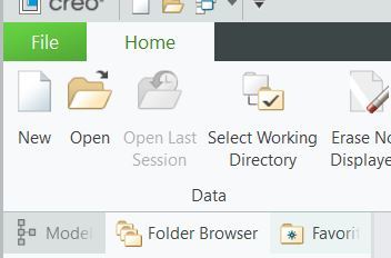
Open Creo Parametric.
Close any pop up windows that might appear.
Select your desired working directory.
Click OK on the window that pops up once you’ve selected your desired working directory.
Click New.
Select Sketch.
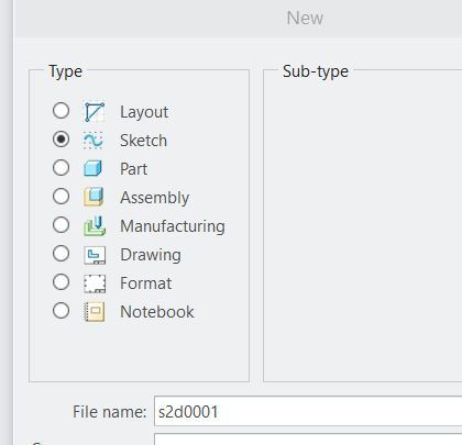
Click OK.
Go to File -> Options -> Sketcher.
Under “Accuracy and Sensitivity” change the Number of decimal places for dimensions to 3 (I like to use 3 decimal places).
Click OK.
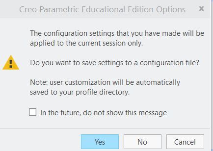
Click No at the prompt.
Click the small arrow next to Rectangle on the Sketch tab on the top of your screen.
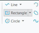
Select Center Rectangle.
Click a point anywhere.
Drag to create a rectangle.
Click another point to create the rectangle.
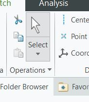
Click the Select button to stop creating rectangles.
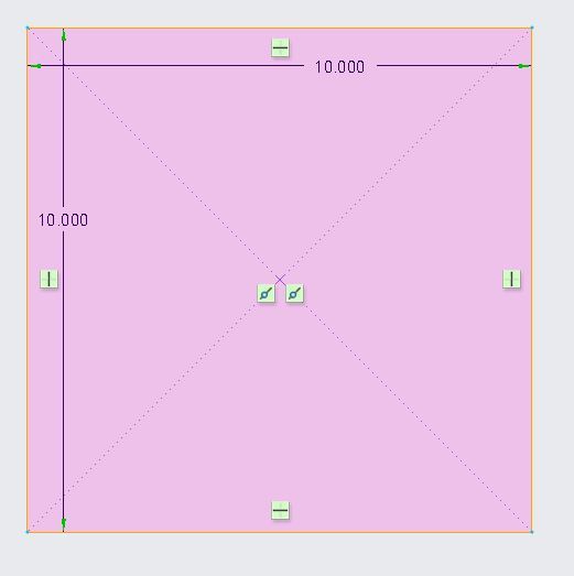
Double-click on one of the dimensions in order to alter it. In this case, I will make both the length and the width equal to 10.000.
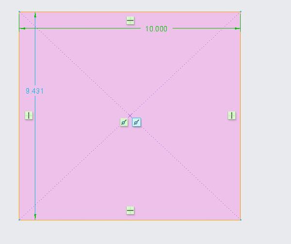
The little green squares indicate the constraints. For example, the green square with the black line indicates that the corresponding side of the square is exactly horizontal. Likewise, the sides are vertical.
To shift the view on the screen, you hold down the Shift key on your keyboard while holding down the middle mouse button (or pressing the scroll wheel on your mouse). It is a bit awkward, but it is what it is.
Similarly, to rotate the object in your view, hold down the Ctrl key on your keyboard while pressing the middle mouse button (or pressing the scroll wheel on your mouse).
You can move the position of the dimension labels (e.g. the 10.000 markets) but click on them and dragging them to where you want them to be.
To save your rectangle, go to File -> Save and then click OK.
How to Sketch a Circle in 2D
Let’s add a circle to our sketch.
Click the arrow next to Circle.
Select Center and Point.
Click where you want the center of the circle to be.
Drag your mouse outward to increase the size of the circle.
Click the Select button when done.
How to Delete a Segment
In order to make our figure a complete solid, we need to delete a segment.
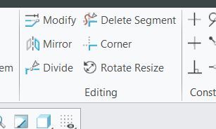
Click Delete Segment in the upper right.
Click and drag your mouse over the segments you want to delete. In my case, I deleted one half of the circle we just created.
When you are done, click Select (or hit your scroll wheel button somewhere on the canvas away from the sketch you’re creating).
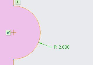
To modify the radius of the circle we’ve created, click on the radius number that is labeled with an ‘R’.
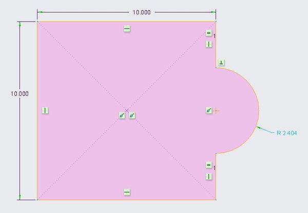
You can choose any number. I’ll select 2.000.
How to Create a Hole
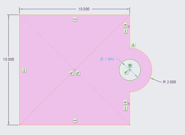
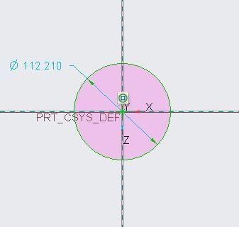
Let’s create a circle within the circle we created.
Click the arrow next to the Circle button.
Hover over the center of the original circle you created and click.
Drag your circle to your desired dimensions then click Select.
The diameter of my inner circle is 1.943.
To save what we have so far, go to File -> Save or click the Save icon at the top-left of the window.
How to Create a New Part in 3D Using Extrude
To create a new part, click on File -> New.
The default selection for Type is Part and Solid for Sub-type. These are fine.
Uncheck the Use default template checkbox.
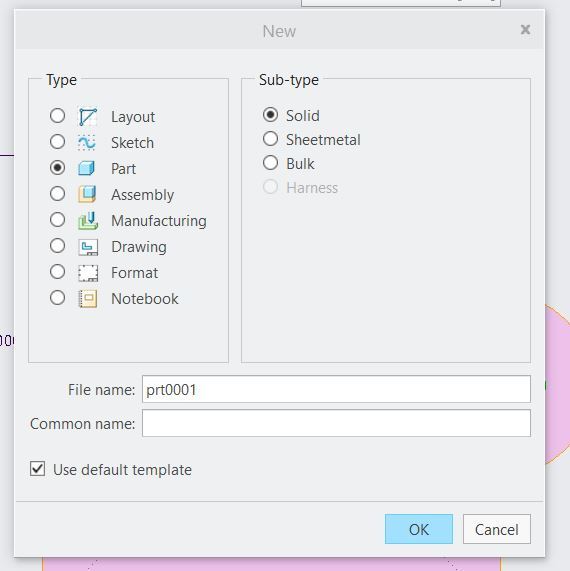
Click OK.
Select your units. Creo Parametric enables you to choose a variety of predefined systems of units.
I’ll select mmns_part_solid. mmns means millimeter Newton second, where all lengths are in millimeters, force will be in Newtons, and time will be in seconds.
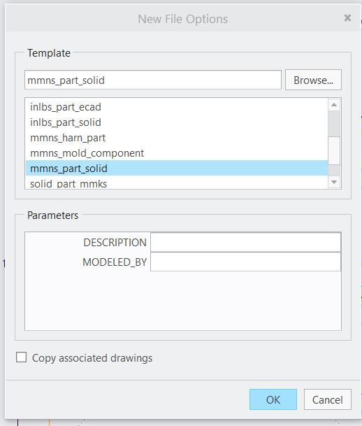
Click OK.
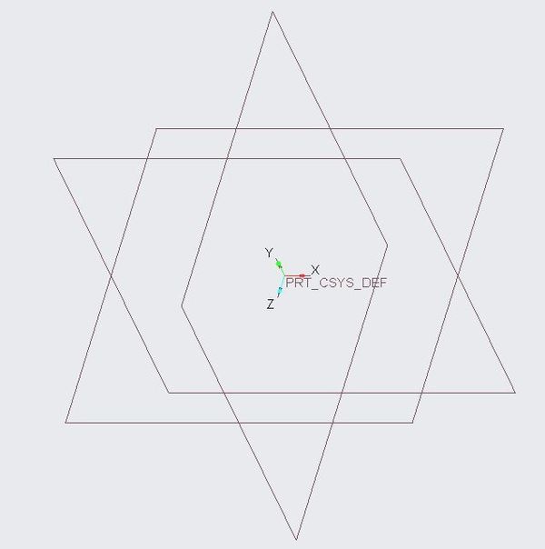
What you see in front of you are three different planes: RIGHT, TOP, and FRONT. These are the three dimensions that your part design will be limited to.
In Creo Parametric, the defaults are:
- RIGHT = YZ plane
- TOP = XZ plane
- FRONT = XY plane
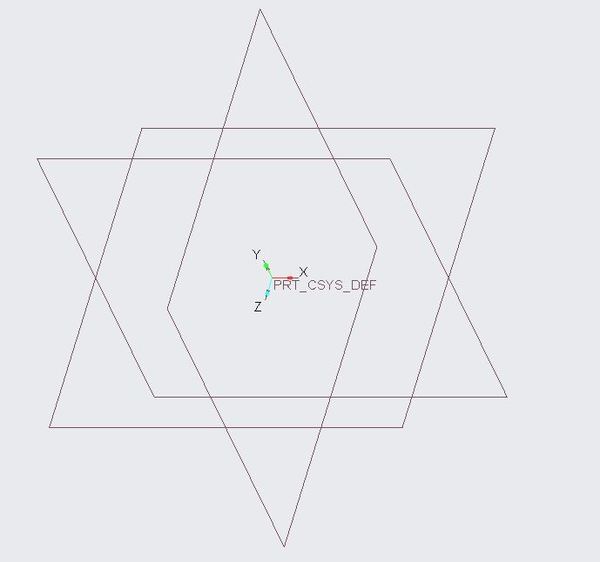
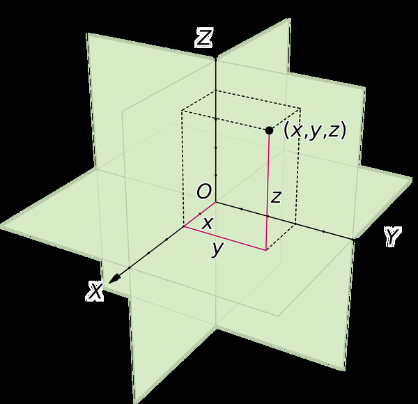
Let’s select the FRONT plane by clicking on it. This is your standard XY plane in the Cartesian Coordinate system.
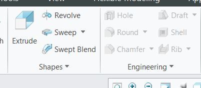
Click the Extrude button.
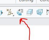
Click the Sketch View button to flatten the sketch. The Sketch View button is on the small toolbar above the sketch.
Click File System in the upper-left part of the screen.
Select the file we’ve been working on so far and click Open.
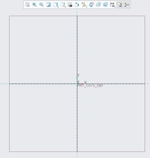
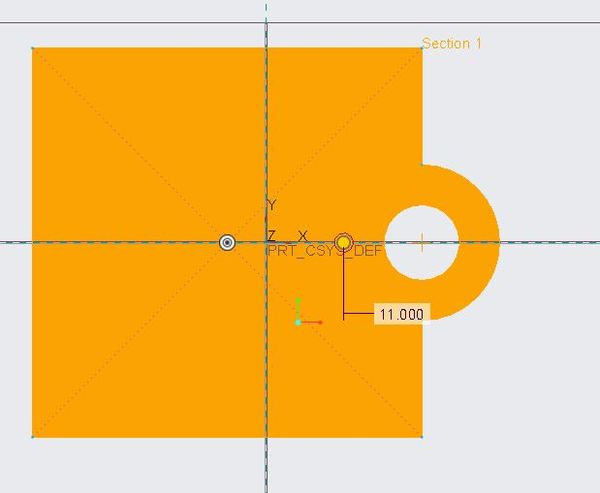
Click in the middle of the screen to place the sketch.
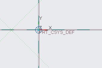
Move it to the center of the x-y reference lines by clicking the circle in the middle and dragging it to the origin.
Up top on the bar, you can scale the image to 1.000. To the left of the green checkmark you should see a white box. Put 1.000 in this box, and then click the green checkmark.
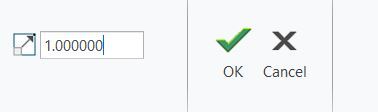
Now press OK again.
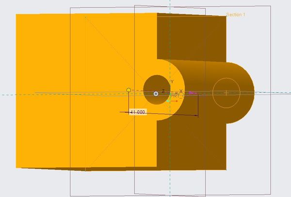
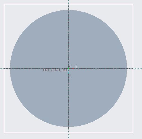
Hold down the middle mouse button (or scroll wheel) while moving your wrist in order to rotate the object and see it in three dimensions.
Change the Depth to 2.000.
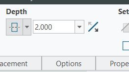
Click OK.
Save it by going to File -> Save or clicking the Save icon at the top-left of the window.
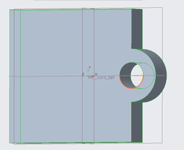
To examine the dimensions of the part, click on Extrude 1 on the left side of the window.
Press Ctrl + E or click the Edit Definition button.
Click Placement -> Edit.
Click the Sketch View icon on the small toolbar to flatten the sketch. You can see the dimensions.
Now click OK.
Click OK again.
That’s it.
How to Create Additional Parts
Go to File -> New.
Select Part, Solid, and uncheck ‘Use default template’. You can enter any File name you would like.
Choose mmns_part_solid and click OK.
Click on Extrude.
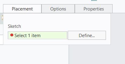
Click Placement -> Define.
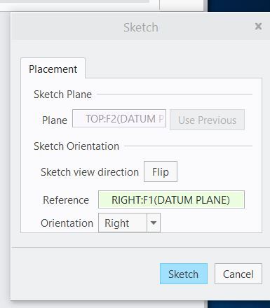
Click on the Right plane.
Click Sketch.
Click the Sketch View button to flatten the plane.
Click the arrow next to the Circle button.
Select Center and Point.
Click in the origin of the plane and spread your circle out to your desired dimensions.
Click Select.
Change the diameter to 2.000. You do that by double-clicking on the current number and entering in your desired diameter.
Click OK.
Change the Depth to 20.000.
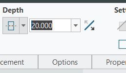
Click OK.
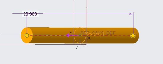
If you’re unable to find your part, you can always put it inside the view using the magnifying glass on the left side of the small toolbar.

How to Modify an Extruded Part
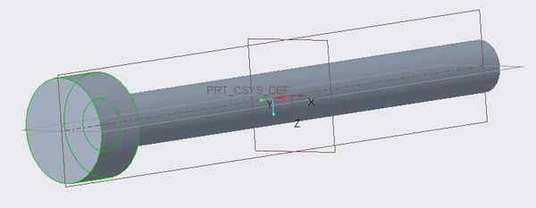
Right now, all we have is a cylinder. Let’s make our cylinder a nail. To do that, we need to add a head to the cylinder.
Click Extrude again.
Select a surface. I’ll select the circle.
Click the Sketch View button.
Click the arrow next to the Circle button.
Click Center and Point.
Click your mouse in the center of the circle and spread it out.
Ensure your circle has a diameter of 4.000.
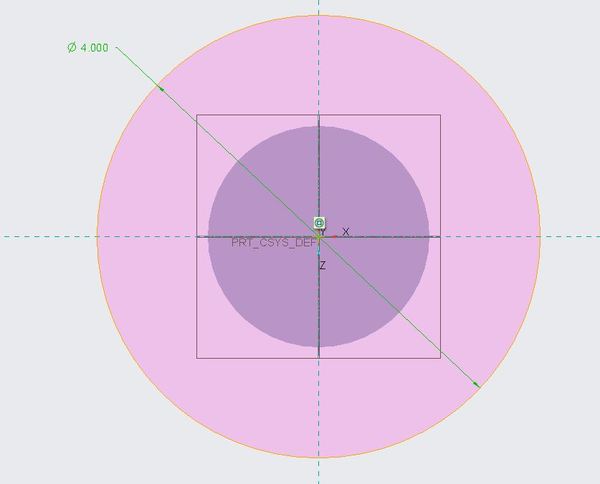
Click OK.
Change the depth to 2.000.
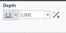
Press OK.
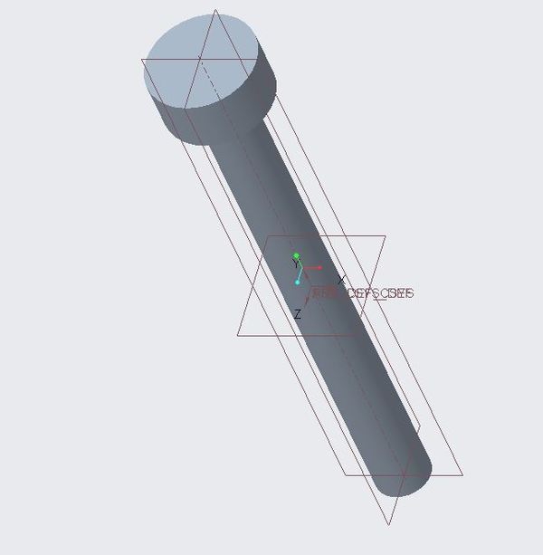
Voila! Rotate the image, and you can see we have created a nail.
Let’s save the part. Go to File -> Save, and click OK.
How to Create an Assembly
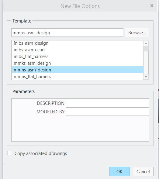
Go to File -> New.
Select Assembly -> Design.
Uncheck ‘Use default template’.
Click OK.
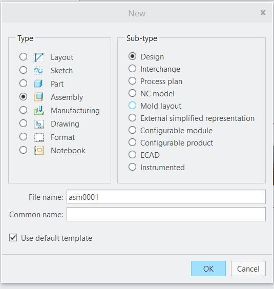
Select mmns_asm_design.
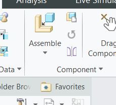
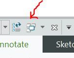
Click Assemble in the upper-left part of the window.
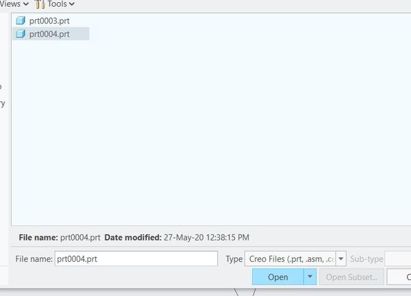
Find the part you just created and click Open.
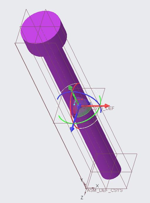
Where it says “Automatic,” select “Default.”
Click OK. Here is what you should now see.
Click on Assemble again.
Open the circle-rectangle combination part we created at the start of this tutorial.
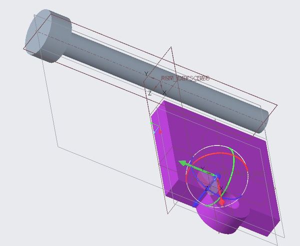
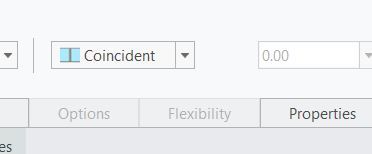
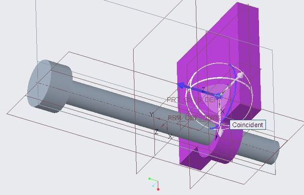
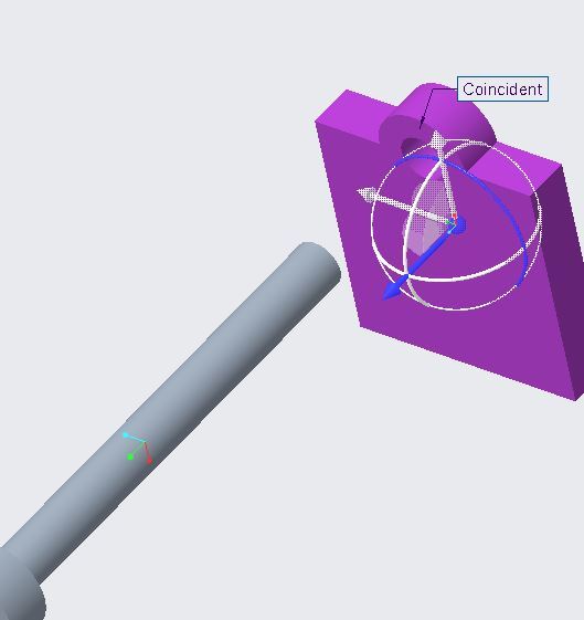
Change the drop-down from Automatic to Coincident.
Click on a part of the long cylinder.
Drag your mouse to the surface of the hole on the circle-rectangle plate.
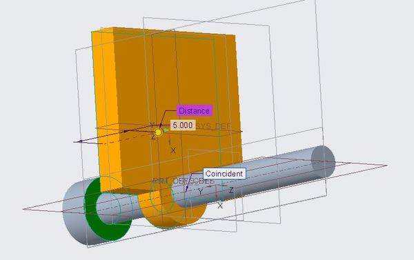
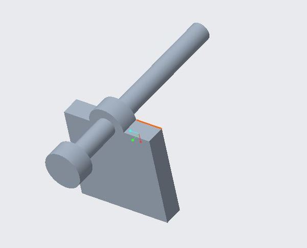
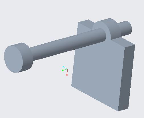
You see that the nail is now inside the hole.
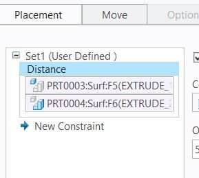
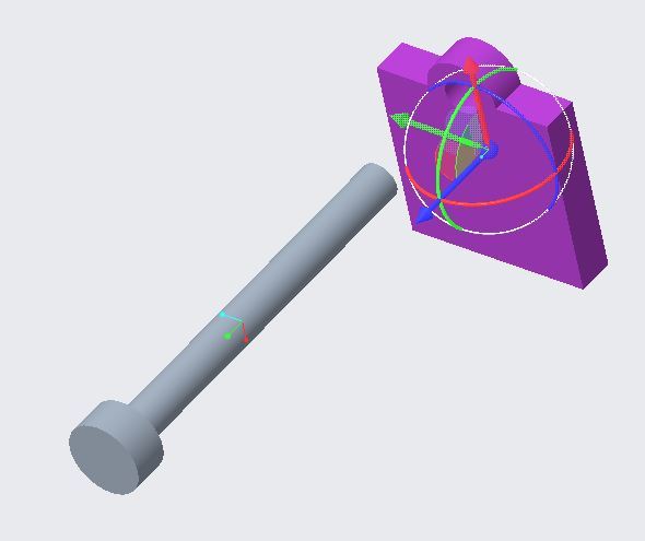
Let’s make the distance from the circle-rectangle plate to the nail head 5.00.
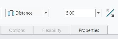
Click the surface of the plate.
Rotate the assembly, and click the nail surface.
Change the distance to 5.000.
Go to File Save.
How to Create Drawing Views
Go to File -> New.
Uncheck ‘Use default template’.
Click OK.
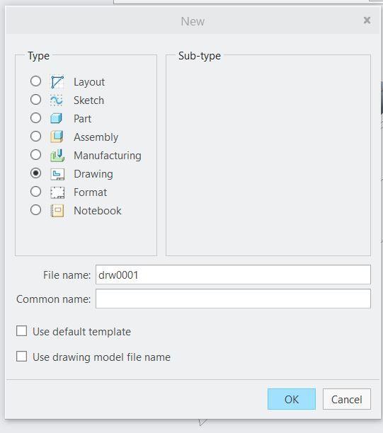
Change the paper size to A4.
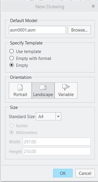
Click OK.
Click on General View -> OK.
Click somewhere within the drawing.
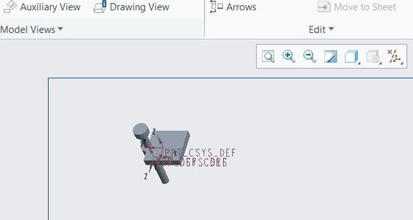
On the pop up window, select Standard Orientation.
Click Apply.
Click OK.
Click the Drawing Model button.
Click Add Model.
Select the circle-rectangle plate part.
Click Open
Click Done/Return.
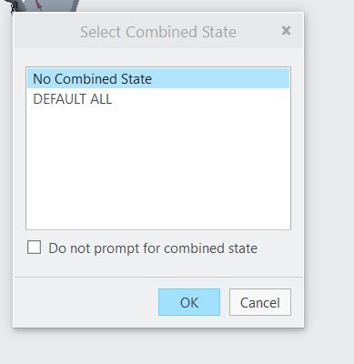
Click General View.
Select No Combined State.
Click OK.
Change Custom Scale to 2.000.
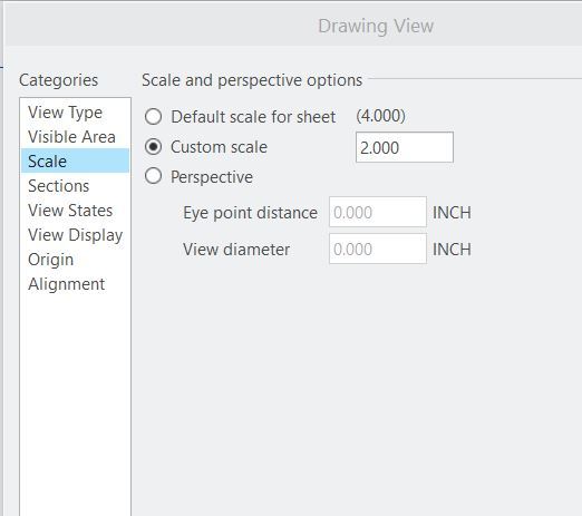
Click Apply.
Click on the part.
Click on Projection View.
Click somewhere outside the part.
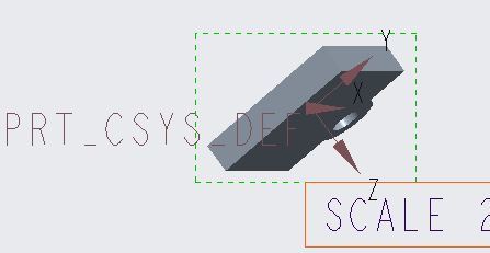
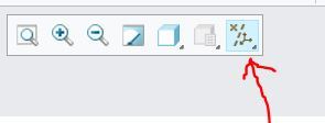
To turn the axis off, click on the axis button on the small toolbar, and click “Select All.”
To delete the scale label, click on it and hit delete.
Click on the part again.
Click Projection View.
Edit the definition.
Click View Display, and change the Display style to ‘Hidden.’
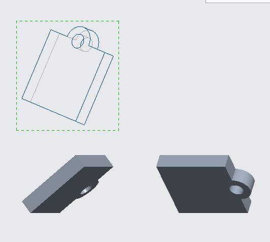
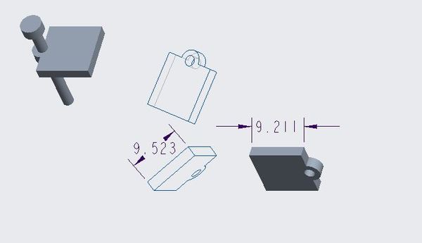
You can do the same for another of your parts, and select ‘No Hidden’. Here are the results of that.
How to Annotate Dimensions on a Drawing
To add dimensions to a drawing, click the Annotate tab.
Click Dimensions.
Click on a side of the part, and see the dimensions.
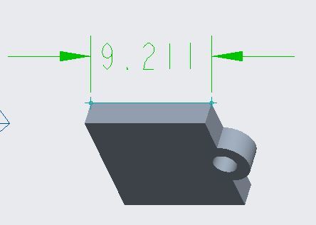
Here is our drawing so far.
How to Export a Drawing as a PDF File
Go to File -> Save As -> Export.
Select pdf.
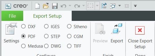
Click Export.
Click OK.
Your PDF will pop up.
Close Export Set Up.
How to Use Mechanisms
Mechanisms in Creo Parametric enable cool animations.
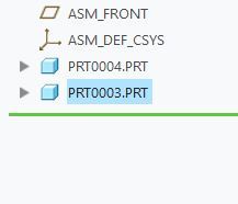
At the top-left of your window, there is a small arrow that enables you to change windows. Go to the assembly .ASM file.
On the left-hand side, select the circle-rectangle plate part, and click the Edit Definition icon (or type Ctrl+E).
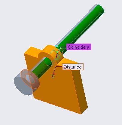
Click Placement.
Right-click on Coincident.
Click Delete.
Right Click on Distance.
Click Delete.
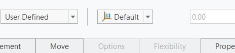
Go to User Defined dropdown menu, and Select Pin.
Click the arrow on the circle-rectangle plate that is parallel to the nail and hold down your mouse.
Slide the plate off the nail.
Click the interior hole of the circle-plate combination.
Drag the cursor to a point on the nail cylinder (i.e. shaft). We have now connected the two surfaces.
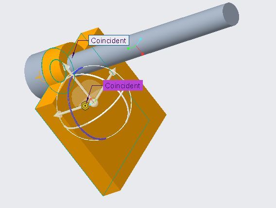
Now click on the flat part of the circle-rectangle plate, and connect that surface to the surface of the nail head that faces the plate.
In the dropdown menu, select Distance.
Change Distance to 20.000.
Now change to 15.000.
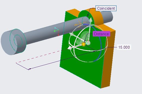
Click OK (the green check).
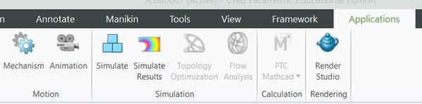
Click the Applications tab.
Click Mechanism.
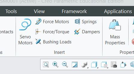
Click the Servo Motors tab.
Click Profile Details.
Select Velocity in the dropdown menu.
Change Velocity to 10 mm/sec.
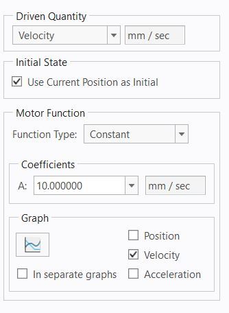
Now click on the part.
Press OK.
Click on Mechanism Analysis.
Change End Time to 100.
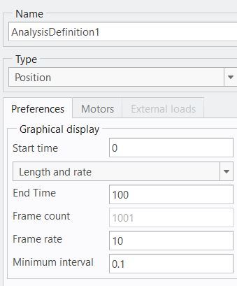
Click Run to run the animation. Here is what you should see:

You can exit when you want to.
Regenerate the model in order to rebuild the changes you have just made.
Click Save.
You can exit the software.
That’s it!
What I have shown you is a quick taste of some of the things Creo Parametric enables you to do. There is much more functionality than what we’ve gone through, but you now have experience with the basics.
Keep building!