
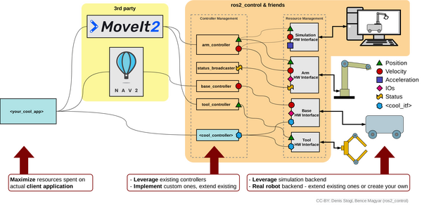
In this tutorial, I will guide you through the process of simulating and performing basic control of a robotic arm in Gazebo. By the end of this tutorial, you will be able to build this:
Gazebo is a robotics simulator that enables the testing and development of robots in a virtual environment. It supports a wide range of robots and integrates seamlessly with ROS 2, facilitating the transition from simulation to real-world application. This makes Gazebo an essential tool for roboticists aiming to prototype and refine algorithms efficiently.
Before we begin, I should advise you that Gazebo has been going through a lot of changes over the last several years. These changes are discussed here. They have changed the name several times and have not fully ported all the ROS plugins from the old classic Gazebo to the new Gazebo simulation engine (some folks still call the new Gazebo, “Ignition”, although it is no longer called Ignition).
For this reason, I have split this tutorial into two sections: Gazebo (new version) and Gazebo Classic (old version). I will show you how to launch and perform basic control of a robotic arm using both Gazebo versions.
Prerequisites
- You understand what a joint and link are.
- You have created a ROS 2 workspace.
- You know what a ROS 2 package is.
- You have created a URDF file for a simulated robotic arm that you want to use in Gazebo. I will be using the myCobot 280 for Arduino by Elephant Robotics.
- If you are using a virtual machine on Ubuntu, I recommend you use Oracle VirtualBox instead of VMWare. I had a lot of issues on VMWare that prevented me from running Gazebo.
- I am using ROS 2 Iron, the most recent version at the time of writing this tutorial, but you are welcome to use other versions of ROS 2 if you prefer.
All my code for this project is located here on GitHub.
Gazebo (new version)
Install Gazebo, ros_gz, and numpy
The first thing we need to do is to install the package that handles the integration between ROS 2 and Gazebo. The name of this package is ros_gz. Here is the GitHub repository, and here are the official installation instructions. Let’s walk through the steps together.
I am using ROS 2 Iron, but regardless of the ROS 2 version you are using, you will need to open a terminal window, and type this command to install the package:
sudo apt-get install ros-${ROS_DISTRO}-ros-gzType Y and press Enter to install the package.
The command above installs ros_gz and the correct version of Gazebo for your ROS 2 version.
Now install Numpy, a scientific computing library for Python.
sudo apt install python3 python3-pippip3 install numpyTest Your Installation
To test your installation, we will run the example from this part of the repo.
ros2 launch ros_gz_sim gz_sim.launch.py gz_args:="shapes.sdf"Here is what you should see:
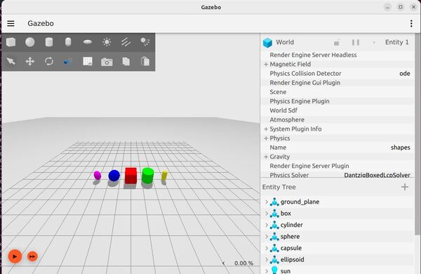
Feel free to run the other demos which you can find here.
When you run each demo, you can explore the topics by typing:
ros2 topic listCreate World Files
The first thing we need to do is to create an environment for your simulated robot.
We are going to create a new package named mycobot_gazebo.
cd ~/ros2_ws/src/mycobot_ros2/ros2 pkg create --build-type ament_cmake --license BSD-3-Clause mycobot_gazebocd mycobot_gazeboCreate a worlds folder:
mkdir worldsAlso, create other folders we will need later:
mkdir launchmkdir modelsNow let’s create our world. This first world we will create is an empty world.
cd worldsgedit empty.worldAdd this code.
<?xml version="1.0" ?>

<sdf version="1.6">
  <world name="default">
    <!-- Plugin for simulating physics -->
    <plugin
      filename="gz-sim-physics-system"
      name="gz::sim::systems::Physics">
    </plugin>

    <!-- Plugin for handling user commands -->
    <plugin
      filename="gz-sim-user-commands-system"
      name="gz::sim::systems::UserCommands">
    </plugin>

    <!-- Plugin for broadcasting scene updates -->
    <plugin
      filename="gz-sim-scene-broadcaster-system"
      name="gz::sim::systems::SceneBroadcaster">
    </plugin>

    <!-- To add realistic gravity, do: 0.0 0.0 -9.8, otherwise do 0.0 0.0 0.0 -->
    <gravity>0.0 0.0 -9.8</gravity>

    <!-- Include a model of the Sun from an external URI -->
    <include>
      <uri>
        https://fuel.gazebosim.org/1.0/OpenRobotics/models/Sun
      </uri>
    </include>

    <!-- Include a model of the Ground Plane from an external URI -->
    <include>
      <uri>
        https://fuel.gazebosim.org/1.0/OpenRobotics/models/Ground Plane
      </uri>
    </include>

    <!-- Define scene properties -->
    <scene>
      <shadows>false</shadows>
    </scene>

  </world>
</sdf>
Save the file, and close it.
This file describes a simulated world using the Simulation Description Format (SDF) version 1.6. It defines a world named “default”.
The world includes three important plugins:
- The physics plugin simulates how objects interact and move in the world.
- The user commands plugin allows people to control things in the simulation.
- The scene broadcaster plugin sends out updates about what’s happening in the world.
Gravity is set to mimic Earth’s gravity, pulling objects downward.
Two models are brought into the world from external sources:
- Sun, which provides light
- Ground Plane, which gives a flat surface for objects to rest on.
The scene settings specify that shadows should not be rendered in this world.
This file serves as a basic template for creating a simulated environment, providing the fundamental elements needed for a functional simulation.
Now let’s create a world called house.world.
gedit house.worldAdd this code.
Save the file, and close it.
This code describes a simulated world using the Simulation Description Format (SDF) version 1.6. It defines a detailed indoor residential environment. The world is named ‘default’ and includes plugins for physics simulation, user commands, and scene broadcasting. Gravity is set to Earth-like conditions.
The scene properties define ambient and background lighting, with shadows, grid, and origin visual turned off. The world is populated with numerous models representing typical household items and furniture. These include structural elements like walls, windows, doors, and flooring, as well as furniture such as beds, chairs, tables, and sofas.
The environment also includes kitchen appliances, electronic devices, decorative items, and various small objects to create a realistic home setting. Each model is positioned precisely within the world using coordinate systems. Many models are marked as static, meaning they won’t move during the simulation.
Lighting is carefully set up with multiple light sources, including a sun for overall illumination and various point and spot lights to simulate indoor lighting. These lights are placed strategically to create a realistic lighting environment, with some casting shadows and others providing ambient illumination.
Create a models folder. These models are physical objects that will exist inside your house world.
cd ..mkdir modelscd modelsMake sure you put these models inside your models folder.
Let’s walk through one of those models. We will take a look at the refrigerator model.
The refrigerator model is defined using the Simulation Description Format (SDF) version 1.6. Here’s a breakdown of its structure:
The model is named “aws_robomaker_residential_Refrigerator_01“. It contains a single link, which represents the main body of the refrigerator.
The link has three main components:
- Inertial properties: A mass of 1 unit is specified, which affects how the object behaves in physical simulations.
- Collision geometry: This defines the shape used for collision detection. It uses a mesh file named “aws_Refrigerator_01_collision.DAE” located in the model’s meshes directory. This mesh is a simplified version of the refrigerator’s shape for efficient collision calculations.
- Visual geometry: This defines how the refrigerator looks in the simulation. It uses a separate mesh file named “aws_Refrigerator_01_visual.DAE“. This mesh is more detailed than the collision mesh to provide a realistic appearance.
Both the collision and visual meshes are scaled to 1:1:1, meaning they use their original size.
The visual component also includes a metadata tag specifying it belongs to layer 1, which is used for rendering or interaction purposes in the simulation environment.
Finally, the model is set to static, meaning it won’t move during the simulation. This is appropriate for a large appliance like a refrigerator that typically stays in one place.
This structure allows the simulation to efficiently handle both the physical interactions and visual representation of the refrigerator in the Gazebo virtual environment.
Oh and one other thing I should mention. DAE (Digital Asset Exchange) files, also known as COLLADA (COLLAborative Design Activity) files, can be created by various 3D modeling and animation software.
The DAE format is widely used in game development, virtual reality, augmented reality, and simulation environments because it’s an open standard that can store 3D assets along with their associated metadata.
For the specific refrigerator model mentioned in the SDF file, it was likely created using a 3D modeling software as part of the AWS RoboMaker residential models set. The modelers would have created both a detailed visual mesh and a simplified collision mesh, exporting each as separate DAE files for use in the simulation environment.
The model.sdf and model.config files are typically created manually using a basic text editor.
Create a URDF File
Now let’s create our URDF file. A URDF (Unified Robot Description Format) file is an XML format file used to describe the physical configuration and properties of a robot in a structured and standard way.
cd ~/ros2_ws/src/mycobot_ros2/mycobot_gazebo/mkdir urdfcd urdfgedit mycobot_280_gazebo.urdf.xacroAdd this code. Then save and close.
XML Declaration
The file begins with an XML declaration. Then, it defines the robot using the tag:
<robot xmlns:xacro="http://wiki.ros.org/xacro" name="mycobot_280">This line specifies that we’re describing a robot named “mycobot_280” and it uses the xacro namespace, which allows for more dynamic URDF creation
World Link
<link name="world"/>This defines a “world” link, which represents the fixed world frame.
If this robotic arm was attached to a humanoid robot, the “world” link would likely be replaced by a link representing the part of the humanoid robot to which the arm is attached. This could be:
- The torso or chest of the humanoid robot
- A shoulder joint or shoulder structure
- An upper body frame or “torso_link”
For example, instead of:
<link name="world"/>

<joint name="virtual_joint" type="fixed">
    <parent link="world"/>
    <child link="base_link"/>
    <origin xyz= "0 0 0" rpy = "0 0 0"/>
</joint>
You might see something like:
<link name="torso_link"/>

<joint name="torso_to_arm_base" type="fixed">
    <parent link="torso_link"/>
    <child link="base_link"/>
    <origin xyz= "0.2 0 0.5" rpy = "0 0 0"/>
</joint>
In this case, “torso_link” would be the parent link to which the arm is attached. The xyz values in the joint would define where on the torso the arm is mounted, and the rpy (roll, pitch, yaw) values would define its orientation relative to the torso.
This change would effectively integrate the robotic arm into the larger structure of the humanoid robot, allowing for coordinated movement between the arm and the rest of the robot’s body.
Properties
<xacro:property name="effort" value="5.0"/>
<xacro:property name="velocity" value="2.792527"/>
These lines define properties that can be reused throughout the file. “effort” is set to 5.0 and “velocity” to 2.792527.
The units for effort and velocity in URDF files are typically as follows:
- Effort: The unit for effort is Newton-meters (N·m). This represents the maximum torque that can be applied by the joint actuator.
- Velocity: The unit for velocity is radians per second (rad/s). This represents the maximum rotational speed of the joint.
In this specific URDF file:
- Effort is set to 5.0, meaning 5.0 N·m
- Velocity is set to 2.792527, meaning 2.792527 rad/s
Links
The file then defines several links. Let’s look at the “base_link” as an example:
	<link name="base_link">

		<inertial>
			<origin xyz="0 0 0.0" rpy="0 0 0"/>
			<mass value="0.33"/>
			<inertia
				ixx="0.000784" ixy="0.0" ixz="0.0"
				iyy="0.000867" iyz="0.0"
				izz="0.001598"/>
		</inertial>
		<visual>
			<geometry>
				<mesh filename="file://$(find mycobot_description)/meshes/mycobot_280/base_link.dae"/>
			</geometry>
			<origin xyz = "0.0 0 -0.03" rpy = "0 0 ${pi/2}"/>
		</visual>
		<collision>
			<geometry>
				<mesh filename="file://$(find mycobot_description)/meshes/mycobot_280/base_link.dae"/>
			</geometry>
			<origin xyz = "0.0 0 -0.03" rpy = "0 0 ${pi/2}"/>
		</collision>
	</link>
Each link has three main sections:
- <inertial>: Defines the mass and inertia of the link. This is crucial for dynamic simulations.
- <visual>: Describes how the link looks, usually referencing a 3D model file.
- <collision>: Defines the shape used for collision detection, often identical to the visual shape.
The file continues to define more links in a similar manner for each part of the robot (link1, link2, etc., up to the gripper components).
Joints
Joints connect links and define how they can move relative to each other. Here’s an example of a revolute joint from the file:
	<joint name="link1_to_link2" type="revolute">
		<axis xyz="0 0 1"/>
		<limit effort = "${effort}" lower = "-2.879793" upper = "2.879793" velocity = "${velocity}"/>
		<parent link="link1"/>
		<child link="link2"/>
	    <origin xyz= "0 0 0.13156" rpy = "0 0 ${pi/2}"/>
        <dynamics damping="0.05" friction="0.05"/>
	</joint>
Joint elements:
- name: Unique identifier for the joint
- type: “revolute” allows rotation around an axis
- axis: Defines the axis of rotation
- limit: Sets limits on effort, velocity, and rotation range
- parent and child: Specify which links this joint connects
- origin: Position and orientation of the joint relative to the parent link
- dynamics: Defines damping and friction properties
The file includes several revolute joints for the main arm segments and the gripper.
Mimic joints: Some gripper joints use the “mimic” property:
<mimic joint="gripper_controller" multiplier="1.0" offset="0" />
This means the joint mimics another joint’s movement, useful for synchronized gripper finger movement.
Gazebo Plugins
You will notice I added plugins at the end of the URDF File. Here is a list of plugins that can be added to our URDF file to create extra functionality.
The two plugins I added are the JointStatePublisher and the JointPositionController.
The JointStatePublisher publishes the state of all joints in a robot to the “/joint_states” topic, including positions (radians or meters), velocities (radians per second or meters per second), and efforts (Nm or N) as a sensor_msgs/JointState message.
The JointPositionController subscribes to target joint angles (i.e. positions) as a std_msgs/Float64 message (i.e. a floating-point number like 0.36).
What Would Happen on a Real Robot?
In a real robotic arm like the myCobot 280 or Kinova Gen3 lite, you wouldn’t need to add Gazebo plugins to your URDF if you’re not using Gazebo for simulation. Instead, you would interface directly with the real hardware. Here’s how the system would typically work:
Robotic Arm Physical Components (myCobot 280 robotic arm with Arduino is the example here)
- The robotic arm has servo motors for each joint (i.e. the movable pieces of the robotic arm). For example, the myCobot 280 uses custom servos, while an arm like Kinova Gen3 lite uses proprietary actuators.
- Each servo motor has a built-in encoder that measures the joint’s position (e.g. ticks, degree, or radians).
- The servo positions are controlled by firmware running on a microcontroller (e.g. Arduino).
- The robotic arm also has a physical motor controller (i.e. an electronic circuit) that controls the voltage and current supplied to move the motor to reach a target angular position based on the commands it receives from Arduino.
- A USB or Ethernet connection links the microcontroller (e.g. Arduino) to your computer.
Microcontroller (e.g. Arduino):
- Receives commands from the computer and sends back to the computer the “state” or position (typically in radians) of each joint.
ROS 2 Control Hardware Interface:
- ROS 2 Control is a software component that bridges between ROS 2 and your myCobot 280’s hardware (via the Arduino).
- You would create a custom hardware interface package for your specific arm.
- For example, you would write a C++ class that inherits from hardware_interface::SystemInterface. This class defines how to communicate with your Arduino board.
- This ROS 2 Control hardware interface would communicate with the Arduino over USB, sending commands to the Arduino and receiving joint states from the Arduino:
- Defines command interfaces for each joint (for sending new position commands).
- Defines state interfaces for each joint (for reading positions).
This hardware interface acts an important link between the physical robot (controlled by the Arduino) and the ROS 2 control system. It abstracts away the hardware-specific details, allowing the rest of the ROS 2 system to work with standardized interfaces.
Controller Manager:
- Moving further away from the hardware and up the software chain, we have the “Controller Manager”.
- Provided by the ros2_control package.
- Load and manage the controllers specified in your configuration (e.g., a joint trajectory controller for coordinated joint motion).
- Handle the lifecycle of these controllers (configure, activate, deactivate).
- Manages the flow of data between the hardware interface and the controllers.
Joint State Broadcaster:
- Part of ros2_controllers.
- Not actually a controller, but a specialized component that reads joint states from the hardware interface.
- The Joint State Broadcaster reads joint states from your custom hardware interface and reports them on the /joint_states topic for components like MoveIt 2 to understand the current state of the robotic arm.
Joint Trajectory Controller:
- Also from ros2_controllers.
- JointTrajectoryController is one of many available ROS 2 controllers. This software controller receives desired trajectories for the arm joints.
- It generates appropriate commands and sends them to the physical motor controllers (i.e. Arduino) through the ROS 2 control hardware interface.
- Responsible for:
- Receiving desired joint trajectories (e.g., from MoveIt 2 or a custom node) on a topic like /joint_trajectory_controller/joint_trajectory as a trajectory_msgs/msg/JointTrajectory message. Each message contains a series of waypoints, each specifying joint positions (and optionally velocities and accelerations) at specific time points.
- Interpolating between trajectory points to create smooth motion.
- Sending position commands to the hardware interface at a high frequency (typically 100-1000 Hz).
- These commands are then sent to the Arduino, which controls the actual servo motors.
MoveIt 2:
- A motion planning framework that integrates with ROS 2 Control.
- Uses the published joint states to maintain an internal model of the robot’s current state.
- For the myCobot280, it would:
- Receive a goal pose for the gripper (e.g., from a user interface or task planner).
- Use its knowledge of the robot’s kinematics to plan a collision-free path to the goal pose
- Generate a joint trajectory to achieve this path.
- Send this trajectory to the Joint Trajectory Controller for execution.
Summary of the Workflow for an Example Pick and Place System Using ROS 2 Control and MoveIt 2
Here is how it would all work for a real robotic arm with perhaps a depth camera (like the Intel RealSense) involved to see objects in the world.
Hardware Interface Operation:
- Polls Arduino via USB (e.g., 100Hz), requesting joint positions.
- Receives raw data (degrees), converts to radians, updates internal state.
- Topic: N/A (internal communication)
Joint State Broadcasting:
- Joint State Broadcaster (50Hz):
- Reads latest joint positions from Hardware Interface.
- Publishes to topic: /joint_states
- Message type: sensor_msgs/msg/JointState
RealSense Camera Operation:
- Captures depth and RGB data (30Hz).
- Publishes to topics:
- /camera/depth/image_rect_raw (sensor_msgs/msg/Image)
- /camera/color/image_raw (sensor_msgs/msg/Image)
- /camera/aligned_depth_to_color/image_raw (sensor_msgs/msg/Image)
- /camera/color/depth/pointcloud (sensor_msgs/msg/PointCloud2)
MoveIt 2 State Monitoring:
- Subscribes to /joint_states
- Updates internal robot model
- (Optionally) Processes /camera/depth/color/points for obstacle avoidance
Motion Planning with MoveIt 2:
- When new goal set (e.g., “move gripper to object detected by camera”):
- Plans collision-free path using robot state and point cloud data
- Generates trajectory (series of time-stamped joint positions)
- Publishes to topic: /joint_trajectory_controller/joint_trajectory
- Message type: trajectory_msgs/msg/JointTrajectory
Joint Trajectory Controller Execution:
- Subscribes to /joint_trajectory_controller/joint_trajectory
- Interpolates between trajectory points
- High-frequency loop (100Hz):
- Calculates desired joint positions
- Sends joint position commands to Hardware Interface
Hardware Interface Command Translation:
- Receives commands from Joint Trajectory Controller
- Converts radians to degrees
- Packages commands for Arduino
- Sends via USB
Arduino Execution:
- Listens for USB commands
- Parses data, extracts joint positions
- Sets servo motor positions
Gripper Control:
- Separate node for gripper control subscribes to custom topic
- Topic: /gripper_command
- Message type: std_msgs/msg/Float32 (0.0 for fully open, 1.0 for fully closed)
- Publishes commands to Hardware Interface for gripper servo
Visual Servoing (optional):
- Custom node processes /camera/color/image_raw
- Detects objects or fiducial markers
- Publishes gripper goals to MoveIt 2
- Topic: /move_group/goal
- Message type: moveit_msgs/msg/MoveGroupActionGoal
This setup integrates the depth camera data into the control loop, allowing for:
- Object detection and localization
- Dynamic obstacle avoidance
- Visual servoing for precise gripper positioning
The system maintains the abstraction of the myCobot280’s Arduino control, while adding the capability to react to its environment using the RealSense camera. This makes it suitable for tasks like pick-and-place operations, where the robot can locate objects with the camera and plan motions to grasp them with the gripper.
Create the Parameters File
To enable Gazebo to communicate with to ROS 2 topics and vice versa, you need to set up a parameter file that bridges the topics between the two platforms. You can see tutorials of how this works here on GitHub (for ROS 2 Iron and older)
Open a new terminal window, and type:
cd ~/ros2_ws/src/mycobot_ros2/mycobot_gazebo/mkdir configcd configgedit ros_gz_bridge.yamlAdd this code, and then save the file.
The first part of the file deals with a topic called joint_states, which is published by the JointState plugin. This means that data about the joint states of the robot is being sent from Gazebo to ROS.
The rest of the file lists topics that the JointPositionController plugin subscribes to. This means that these topics are used to send commands to specific joints of the robot from ROS to Gazebo.
Create the Launch File
Let’s create a launch file to spawn both our world and our robotic arm.
cd ~/ros2_ws/src/mycobot_ros2/mycobot_gazebo/mkdir launchcd launchgedit mycobot_280_arduino_bringup_gazebo.launch.pyAdd this code.
# Author: Addison Sears-Collins
# Date: July 8, 2024
# Description: Launch a robotic arm in Gazebo
import os
from launch import LaunchDescription
from launch.actions import AppendEnvironmentVariable, DeclareLaunchArgument, IncludeLaunchDescription
from launch.conditions import IfCondition
from launch.launch_description_sources import PythonLaunchDescriptionSource
from launch.substitutions import Command, LaunchConfiguration, PythonExpression
from launch_ros.actions import Node
from launch_ros.parameter_descriptions import ParameterValue
from launch_ros.substitutions import FindPackageShare

def generate_launch_description():

  # Constants for paths to different files and folders
  package_name_description = 'mycobot_description'
  package_name_gazebo = 'mycobot_gazebo'

  default_robot_name = 'mycobot_280'
  gazebo_launch_file_path = 'launch'
  gazebo_models_path = 'models'
  ros_gz_bridge_config_file_path = 'config/ros_gz_bridge.yaml'
  rviz_config_file_path = 'rviz/mycobot_280_arduino_view_description.rviz'
  urdf_file_path = 'urdf/mycobot_280_gazebo.urdf.xacro'
  world_file_path = 'worlds/empty.world' # e.g. 'worlds/empty.world', 'worlds/house.world'

  # Set the path to different files and folders.
  pkg_ros_gz_sim = FindPackageShare(package='ros_gz_sim').find('ros_gz_sim')
  pkg_share_description = FindPackageShare(package=package_name_description).find(package_name_description)
  pkg_share_gazebo = FindPackageShare(package=package_name_gazebo).find(package_name_gazebo)

  default_ros_gz_bridge_config_file_path = os.path.join(pkg_share_gazebo, ros_gz_bridge_config_file_path)
  default_rviz_config_path = os.path.join(pkg_share_description, rviz_config_file_path)
  default_urdf_model_path = os.path.join(pkg_share_gazebo, urdf_file_path)
  gazebo_launch_file_path = os.path.join(pkg_share_gazebo, gazebo_launch_file_path)
  gazebo_models_path = os.path.join(pkg_share_gazebo, gazebo_models_path)
  world_path = os.path.join(pkg_share_gazebo, world_file_path)

  # Launch configuration variables specific to simulation
  headless = LaunchConfiguration('headless')
  robot_name = LaunchConfiguration('robot_name')
  rviz_config_file = LaunchConfiguration('rviz_config_file')
  urdf_model = LaunchConfiguration('urdf_model')
  use_robot_state_pub = LaunchConfiguration('use_robot_state_pub')
  use_rviz = LaunchConfiguration('use_rviz')
  use_sim_time = LaunchConfiguration('use_sim_time')
  use_simulator = LaunchConfiguration('use_simulator')
  world = LaunchConfiguration('world')

  # Set the default pose
  x = LaunchConfiguration('x')
  y = LaunchConfiguration('y')
  z = LaunchConfiguration('z')
  roll = LaunchConfiguration('roll')
  pitch = LaunchConfiguration('pitch')
  yaw = LaunchConfiguration('yaw')

  # Declare the launch arguments
  declare_robot_name_cmd = DeclareLaunchArgument(
    name='robot_name',
    default_value=default_robot_name,
    description='The name for the robot')

  declare_rviz_config_file_cmd = DeclareLaunchArgument(
    name='rviz_config_file',
    default_value=default_rviz_config_path,
    description='Full path to the RVIZ config file to use')

  declare_simulator_cmd = DeclareLaunchArgument(
    name='headless',
    default_value='False',
    description='Display the Gazebo GUI if False, otherwise run in headless mode')

  declare_urdf_model_path_cmd = DeclareLaunchArgument(
    name='urdf_model',
    default_value=default_urdf_model_path,
    description='Absolute path to robot urdf file')

  declare_use_robot_state_pub_cmd = DeclareLaunchArgument(
    name='use_robot_state_pub',
    default_value='True',
    description='Whether to start the robot state publisher')

  declare_use_rviz_cmd = DeclareLaunchArgument(
    name='use_rviz',
    default_value='True',
    description='Whether to start RVIZ')

  declare_use_sim_time_cmd = DeclareLaunchArgument(
    name='use_sim_time',
    default_value='true',
    description='Use simulation (Gazebo) clock if true')

  declare_use_simulator_cmd = DeclareLaunchArgument(
    name='use_simulator',
    default_value='True',
    description='Whether to start Gazebo')

  declare_world_cmd = DeclareLaunchArgument(
    name='world',
    default_value=world_path,
    description='Full path to the world model file to load')

  declare_x_cmd = DeclareLaunchArgument(
    name='x',
    default_value='0.0',
    description='x component of initial position, meters')

  declare_y_cmd = DeclareLaunchArgument(
    name='y',
    default_value='0.0',
    description='y component of initial position, meters')

  declare_z_cmd = DeclareLaunchArgument(
    name='z',
    default_value='0.05',
    description='z component of initial position, meters')

  declare_roll_cmd = DeclareLaunchArgument(
    name='roll',
    default_value='0.0',
    description='roll angle of initial orientation, radians')

  declare_pitch_cmd = DeclareLaunchArgument(
    name='pitch',
    default_value='0.0',
    description='pitch angle of initial orientation, radians')

  declare_yaw_cmd = DeclareLaunchArgument(
    name='yaw',
    default_value='0.0',
    description='yaw angle of initial orientation, radians')

  # Specify the actions

  set_env_vars_resources = AppendEnvironmentVariable(
    'GZ_SIM_RESOURCE_PATH',
    gazebo_models_path)

  # Start Gazebo server
  start_gazebo_server_cmd = IncludeLaunchDescription(
    PythonLaunchDescriptionSource(
      os.path.join(pkg_ros_gz_sim, 'launch', 'gz_sim.launch.py')),
    condition=IfCondition(use_simulator),
    launch_arguments={'gz_args': ['-r -s -v4 ', world], 'on_exit_shutdown': 'true'}.items())

  # Start Gazebo client
  start_gazebo_client_cmd = IncludeLaunchDescription(
    PythonLaunchDescriptionSource(
      os.path.join(pkg_ros_gz_sim, 'launch', 'gz_sim.launch.py')),
    launch_arguments={'gz_args': '-g -v4 '}.items(),
    condition=IfCondition(PythonExpression([use_simulator, ' and not ', headless])))

  # Subscribe to the joint states of the robot, and publish the 3D pose of each link.
  robot_description_content = ParameterValue(Command(['xacro ', urdf_model]), value_type=str)
  start_robot_state_publisher_cmd = Node(
    condition=IfCondition(use_robot_state_pub),
    package='robot_state_publisher',
    executable='robot_state_publisher',
    name='robot_state_publisher',
    output='screen',
    parameters=[{
      'use_sim_time': use_sim_time,
      'robot_description': robot_description_content}])

  # Launch RViz
  start_rviz_cmd = Node(
    condition=IfCondition(use_rviz),
    package='rviz2',
    executable='rviz2',
    name='rviz2',
    output='screen',
    arguments=['-d', rviz_config_file])

  # Spawn the robot
  start_gazebo_ros_spawner_cmd = Node(
    package='ros_gz_sim',
    executable='create',
    arguments=[
      '-name', robot_name,
      '-topic', 'robot_description',
      '-x', x,
      '-y', y,
      '-z', z,
      '-R', roll,
      '-P', pitch,
      '-Y', yaw
      ],
    output='screen')

  # Bridge ROS topics and Gazebo messages for establishing communication
  start_gazebo_ros_bridge_cmd = Node(
    package='ros_gz_bridge',
    executable='parameter_bridge',
    parameters=[{
      'config_file': default_ros_gz_bridge_config_file_path,
    }],
    output='screen'
  )

  # Create the launch description and populate
  ld = LaunchDescription()

  # Declare the launch options
  ld.add_action(declare_robot_name_cmd)
  ld.add_action(declare_rviz_config_file_cmd)
  ld.add_action(declare_simulator_cmd)
  ld.add_action(declare_urdf_model_path_cmd)
  ld.add_action(declare_use_robot_state_pub_cmd)
  ld.add_action(declare_use_rviz_cmd)
  ld.add_action(declare_use_sim_time_cmd)
  ld.add_action(declare_use_simulator_cmd)
  ld.add_action(declare_world_cmd)

  ld.add_action(declare_x_cmd)
  ld.add_action(declare_y_cmd)
  ld.add_action(declare_z_cmd)
  ld.add_action(declare_roll_cmd)
  ld.add_action(declare_pitch_cmd)
  ld.add_action(declare_yaw_cmd)

  # Add any actions
  ld.add_action(set_env_vars_resources)
  ld.add_action(start_gazebo_server_cmd)
  ld.add_action(start_gazebo_client_cmd)
  ld.add_action(start_robot_state_publisher_cmd)
  ld.add_action(start_rviz_cmd)

  ld.add_action(start_gazebo_ros_spawner_cmd)
  ld.add_action(start_gazebo_ros_bridge_cmd)

  return ld
Save the file, and close it.
Edit package.xml
Now let’s modify our package.xml file to update the package dependencies.
cd ~/ros2_ws/src/mycobot_ros2/mycobot_gazebo/gedit package.xmlAdd this code. Save the file, and then close it.
Update CMakeLists.txt
Go to the CMakeLists.txt, and make sure it looks like this:
cd ~/ros2_ws/src/mycobot_ros2/mycobot_gazebo/gedit CMakeLists.txtYou can comment out or remove any folders or scripts in CMakeLists.txt that we have not yet created in this tutorial (e.g. test_set_joint_position_publisher.py). Be sure to do this before running “colcon build” below.
Save the file, and close it.
cd ~/ros2_ws/Make sure all dependencies are installed.
rosdep install --from-paths src --ignore-src -r -yBuild the package.
colcon buildsource ~/.bashrcLaunch the World and URDF Files Together
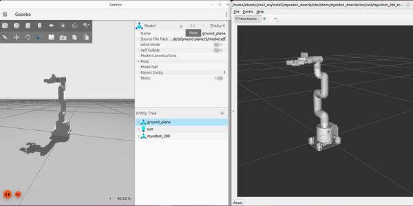
Run the launch file using the following command:
ros2 launch mycobot_gazebo mycobot_280_arduino_bringup_gazebo.launch.pyHere is the output using the empty.world file:
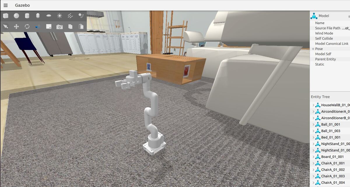
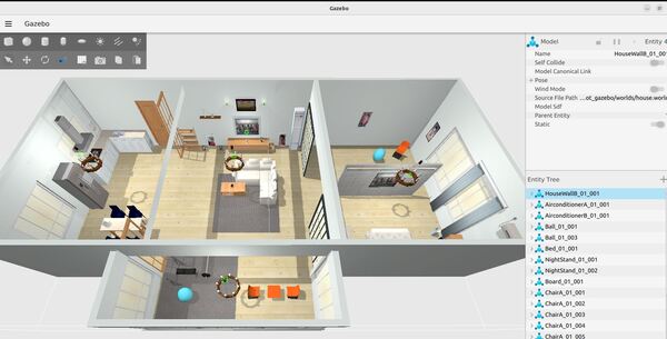
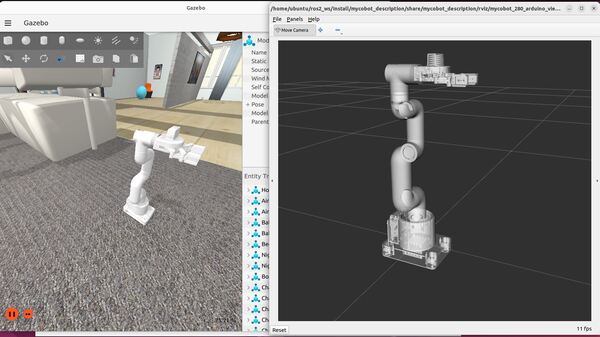
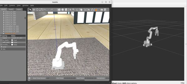
Here is the output using the house.world file. You might see a pop up asking if you would like to Force Quit Gazebo…just wait and be patient for everything to load (house.world is full of SDF models):
To see a list of active topics, type:
ign topic -lTo see the options, you can type:
ign topic -helpGazebo often doesn’t close cleanly, so if you have trouble loading Gazebo, reboot your computer.
Move the Robotic Arm Manually
I could not get the JointTrajectoryController to work in this new Gazebo. As I mentioned earlier, things are moving fast over at Gazebo, and not all the plugins have been transitioned over. However, I was able to get the JointPositionController to work and make the arm move.
To send joint angles to the robot using ROS 2, type this in a terminal window:
ros2 topic pub -1 /model/mycobot_280/joint/link1_to_link2/cmd_pos std_msgs/msg/Float64 '{data: -2.0}'Move the Robotic Arm Using a Script
Let’s create a ROS 2 node that can loop through a list of joint positions to simulate the robotic arm moving from the home position to a goal location and then back to home, repeatedly.
cd ~/ros2_ws/src/mycobot_ros2/mycobot_gazebo/mkdir mycobot_gazebocd mycobot_gazebogedit __init__.pyAdd this code, and then close it.
cd ..mkdir scriptscd scriptsgedit test_set_joint_position_publisher.pyAdd this code:
#! /usr/bin/env python3

"""
Description:
  ROS 2: Executes a sample trajectory for a robotic arm in Gazebo
-------
Publishing Topics (ROS 2):
  Desired goal positions for joints on a robotic arm
    /model/mycobot_280/joint/link1_to_link2/cmd_pos - std_msgs/Float64
    /model/mycobot_280/joint/link2_to_link3/cmd_pos - std_msgs/Float64
    /model/mycobot_280/joint/link3_to_link4/cmd_pos - std_msgs/Float64
    /model/mycobot_280/joint/link4_to_link5/cmd_pos - std_msgs/Float64
    /model/mycobot_280/joint/link5_to_link6/cmd_pos - std_msgs/Float64
    /model/mycobot_280/joint/link6_to_link6flange/cmd_pos - std_msgs/Float64
    /model/mycobot_280/joint/gripper_controller/cmd_pos - std_msgs/Float64
    /model/mycobot_280/joint/gripper_base_to_gripper_left2/cmd_pos - std_msgs/Float64
    /model/mycobot_280/joint/gripper_left3_to_gripper_left1/cmd_pos - std_msgs/Float64
    /model/mycobot_280/joint/gripper_base_to_gripper_right3/cmd_pos - std_msgs/Float64
    /model/mycobot_280/joint/gripper_base_to_gripper_right2/cmd_pos - std_msgs/Float64
    /model/mycobot_280/joint/gripper_right3_to_gripper_right1/cmd_pos - std_msgs/Float64
-------
Author: Addison Sears-Collins
Date: April 18, 2024
"""
import numpy as np
import rclpy # Python client library for ROS 2
from rclpy.node import Node # Handles the creation of nodes
from std_msgs.msg import Float64  # Import the Float64 message


# Define constants
names_of_joints = [ 'link1_to_link2',
                    'link2_to_link3',
                    'link3_to_link4',
                    'link4_to_link5',
                    'link5_to_link6',
                    'link6_to_link6flange',
                    'gripper_controller',
                    'gripper_base_to_gripper_left2',
                    'gripper_left3_to_gripper_left1',
                    'gripper_base_to_gripper_right3',
                    'gripper_base_to_gripper_right2',
                    'gripper_right3_to_gripper_right1']

class BasicJointPositionPublisher(Node):
    """This class executes a sample trajectory for a robotic arm

    """
    def __init__(self):
        """ Constructor.

        """
        # Initialize the class using the constructor
        super().__init__('basic_joint_position_publisher')

        # Create a publisher for each joint
        self.position_publishers = [
            self.create_publisher(Float64, f'/model/mycobot_280/joint/{name}/cmd_pos', 1)
            for name in names_of_joints
        ]
        self.timer_period = 0.05 # seconds
        self.timer = self.create_timer(self.timer_period, self.timer_callback)

        # Starting position and goal position for the robotic arm joints
        self.start_position = [0.0, 0.0, 0.0, 0.0, 0.0, 0.0, 0.0, 0.0, 0.0, 0.0, 0.0, 0.0]
        self.end_position = [-1.345, -1.23, 0.264, -0.296, 0.389, -1.5, -0.7, -0.7, 0.7, 0.7, 0.7, -0.7]

        # Number of steps to interpolate between positions
        self.num_steps = 50

        # Set the desired goal poses for the robotic arm.
        self.positions = self.generate_positions(self.start_position, self.end_position)

        # Keep track of the current trajectory we are executing
        self.index = 0

        # Indicate the direction of movement in the list of goal positions.
        self.forward = True

    def generate_positions(self, start_position, end_position):
        """
        Generates positions along a path from start to end positions.

        Args:
            start_position (list): The starting position of the robotic arm.
            end_position (list): The ending position of the robotic arm.

        Returns:
            list: A complete list of positions including all intermediate steps.
        """
        # Example path including start and end, could be expanded to more waypoints
        path_positions = [start_position, end_position]
        all_positions = []
        for i in range(len(path_positions) - 1):
            interpolated = self.interpolate_positions(path_positions[i], path_positions[i + 1])
            all_positions.extend(interpolated[:-1])  # Exclude the last to avoid duplicates
        all_positions.append(path_positions[-1])  # Ensure the last position is included
        return all_positions

    def interpolate_positions(self, start, end):
        """
        Linearly interpolates between two positions.

        Args:
            start (list): The starting position for interpolation.
            end (list): The ending position for interpolation.

        Returns:
            list: A list of positions including the start, interpolated, and end positions.
        """
        interpolated_positions = [start]  # Initialize with the start position
        step_vector = (np.array(end) - np.array(start)) / (self.num_steps + 1)  # Calculate step vector
        for step in range(1, self.num_steps + 1):
            interpolated_position = np.array(start) + step * step_vector  # Compute each interpolated position
            interpolated_positions.append(interpolated_position.tolist())  # Append to the list
        interpolated_positions.append(end)  # Append the end position
        return interpolated_positions

    def timer_callback(self):
        """Set the goal pose for the robotic arm.

        """
        # Publish the current position for each joint
        for pub, pos in zip(self.position_publishers, self.positions[self.index]):
            msg = Float64()
            msg.data = pos
            pub.publish(msg)

        # Update the trajectory index
        if self.forward:
            if self.index < len(self.positions) - 1:
                self.index =  self.index + 1
            else:
                self.forward = False
        else:
            if self.index > 0:
                self.index = self.index - 1
            else:
                self.forward = True

def main(args=None):

    # Initialize the rclpy library
    rclpy.init(args=args)

    # Create the node
    basic_joint_position_publisher = BasicJointPositionPublisher()

    # Spin the node so the callback function is called.
    rclpy.spin(basic_joint_position_publisher)

    # Destroy the node
    basic_joint_position_publisher.destroy_node()

    # Shutdown the ROS client library for Python
    rclpy.shutdown()

if __name__ == '__main__':
  main()
Update your CMakeLists.txt to include this new script.
Now launch the robot. Wait for everything to come up, including RViz.
ros2 launch mycobot_gazebo mycobot_280_arduino_bringup_gazebo.launch.pyRun the basic joint position publisher to simulate movement for your robotic arm:
ros2 run mycobot_gazebo test_set_joint_position_publisher.pyYour arm will move from a home position to a goal position over and over again. It won’t be the prettiest movement, but we will fix that in a future tutorial.
Gazebo (classic version)
Now let’s take a look at how to simulate and move a robotic arm using the classic version of Gazebo (which will reach end of life in 2025).
Install gazebo_ros_pkgs
Open a new terminal window, and install the packages that will enable you to use ROS 2 to interface with Gazebo Classic.
sudo apt install ros-$ROS_DISTRO-gazebo-ros-pkgsCreate a URDF File
cd ~/ros2_ws/src/mycobot_ros2/mycobot_gazebo/urdfgedit mycobot_280_classic_gazebo.urdf.xacroAdd this code. Then save and close.
Create the Launch File
Let’s create a launch file to spawn both our world and our robotic arm.
cd ~/ros2_ws/src/mycobot_ros2/mycobot_gazebo/launchgedit mycobot_280_arduino_bringup_classic_gazebo.launch.pyAdd this code.
Save the file, and close it.
Create World Files
Create an environment for your simulated robot.
cd ~/ros2_ws/src/mycobot_ros2/mycobot_gazebo/worldsgedit empty_classic.worldAdd this code.
If you want gravity turned ON, the gravity line should look like this:
<gravity>0.0 0.0 -9.8</gravity>
If you want gravity turned OFF, the gravity line should look like this:
<gravity>0.0 0.0 0.0</gravity>
Save the file, and close it.
Now let’s create a world called house_classic.world.
gedit house_classic.worldAdd this code.
Save the file, and close it.
Launch the World and URDF Files Together
Build the Package.
cd ~/ros2_ws/rosdep install --from-paths src --ignore-src -r -ycolcon buildsource ~/.bashrcRun the launch file using the following command:
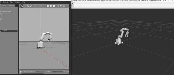
ros2 launch mycobot_gazebo mycobot_280_arduino_bringup_classic_gazebo.launch.pyHere is the output using the empty_classic.world file:
Here is the output using the house_classic.world file:
Move the Robotic Arm Manually
To make the robot move, you use this command:
ros2 topic pub -1 /set_joint_trajectory trajectory_msgs/msg/JointTrajectory "{header: {frame_id: base_link}, joint_names: [link1_to_link2, link2_to_link3, link3_to_link4, link4_to_link5, link5_to_link6, link6_to_link6flange, gripper_controller, gripper_base_to_gripper_left2, gripper_left3_to_gripper_left1, gripper_base_to_gripper_right3, gripper_base_to_gripper_right2, gripper_right3_to_gripper_right1], points: [{positions: [0.0,0.0,0.0,0.0,0.0,0.0,0.0,0.0,0.0,0.0,0.0,0.0]}]}"You can change the values in the positions array to move the robotic arm to different poses.
If you want to close the gripper, the gripper_controller position value needs to be -0.7.
ros2 topic pub -1 /set_joint_trajectory trajectory_msgs/msg/JointTrajectory "{header: {frame_id: base_link}, joint_names: [link1_to_link2, link2_to_link3, link3_to_link4, link4_to_link5, link5_to_link6, link6_to_link6flange, gripper_controller, gripper_base_to_gripper_left2, gripper_left3_to_gripper_left1, gripper_base_to_gripper_right3, gripper_base_to_gripper_right2, gripper_right3_to_gripper_right1], points: [{positions: [-1.345,-1.230,0.264,-0.296,0.389,-1.50,-0.7, -0.7, 0.7, 0.7, 0.7, -0.7]}]}"The two Gazebo plugins defined in the xacro file that make all this work are libgazebo_ros_joint_state_publisher.so (publishes the joint states from Gazebo to ROS 2) and libgazebo_ros_joint_pose_trajectory.so (subscribes to the desired goal poses for the arm that are sent from ROS 2 to Gazebo). That is all you need for basic arm control.
To close Gazebo, press CTRL + C on your keyboard.
Move the Robotic Arm Using a Script
Let’s create a ROS 2 node that can loop through a list of trajectories to simulate the arm moving from the home position to a goal location and then back to home.
cd ~/ros2_ws/src/mycobot_ros2/mycobot_gazebo/scriptsgedit test_set_joint_trajectory_publisher.pyAdd this code:
#! /usr/bin/env python3

"""
Description:
  ROS 2: Executes a sample trajectory for a robotic arm in Gazebo Classic
-------
Publishing Topics (ROS 2):
  Desired goal pose of a robotic arm
  /set_joint_trajectory - trajectory_msgs/JointTrajectory
-------
Author: Addison Sears-Collins
Date: April 18, 2024
"""

import rclpy # Python client library for ROS 2
from rclpy.node import Node # Handles the creation of nodes
from trajectory_msgs.msg import JointTrajectory, JointTrajectoryPoint
from builtin_interfaces.msg import Duration
from std_msgs.msg import Header  # Import the Header message

# Define constants
names_of_joints = [ 'link1_to_link2',
                    'link2_to_link3',
                    'link3_to_link4',
                    'link4_to_link5',
                    'link5_to_link6',
                    'link6_to_link6flange',
                    'gripper_controller',
                    'gripper_base_to_gripper_left2',
                    'gripper_left3_to_gripper_left1',
                    'gripper_base_to_gripper_right3',
                    'gripper_base_to_gripper_right2',
                    'gripper_right3_to_gripper_right1']

class BasicJointTrajectoryPublisher(Node):
    """This class executes a sample trajectory for a robotic arm

    """
    def __init__(self):
        """ Constructor.

        """
        # Initialize the class using the constructor
        super().__init__('basic_joint_trajectory_publisher')

        # Create the publisher of the desired arm goal poses
        self.pose_publisher = self.create_publisher(JointTrajectory, '/set_joint_trajectory', 1)
        self.timer_period = 0.05  # seconds
        self.timer = self.create_timer(self.timer_period, self.timer_callback)

        self.frame_id = "base_link"

        # Set the desired goal poses for the robotic arm.
        # To make the code cleaner, I could have imported these positions from a yaml file.
        self.positions = [
            [0.0, 0.0, 0.0, 0.0, 0.0, 0.0, 0.0, 0.0, 0.0, 0.0, 0.0, 0.0],
            [0.0, 0.0, 0.0, 0.0, 0.0, 0.0, 0.0, 0.0, 0.0, 0.0, 0.0, 0.0],
            [0.0, 0.0, 0.0, 0.0, 0.0, 0.0, 0.0, 0.0, 0.0, 0.0, 0.0, 0.0],
            [0.0, 0.0, 0.0, 0.0, 0.0, 0.0, 0.0, 0.0, 0.0, 0.0, 0.0, 0.0],
            [0.0, 0.0, 0.0, 0.0, 0.0, 0.0, 0.0, 0.0, 0.0, 0.0, 0.0, 0.0],
            [0.0, 0.0, 0.0, 0.0, 0.0, 0.0, 0.0, 0.0, 0.0, 0.0, 0.0, 0.0],
            [0.0, 0.0, 0.0, 0.0, 0.0, 0.0, 0.0, 0.0, 0.0, 0.0, 0.0, 0.0],
            [0.0, 0.0, 0.0, 0.0, 0.0, 0.0, 0.0, 0.0, 0.0, 0.0, 0.0, 0.0],
            [0.0, 0.0, 0.0, 0.0, 0.0, 0.0, 0.0, 0.0, 0.0, 0.0, 0.0, 0.0],
            [0.0, 0.0, 0.0, 0.0, 0.0, 0.0, 0.0, 0.0, 0.0, 0.0, 0.0, 0.0],
            [-0.0269, -0.0246, 0.00528, -0.00592, 0.00778, -0.03, 0.0, 0.0, 0.0, 0.0, 0.0, 0.0],
            [-0.0538, -0.0492, 0.01056, -0.01184, 0.01556, -0.06, 0.0, 0.0, 0.0, 0.0, 0.0, 0.0],
            [-0.0807, -0.0738, 0.01584, -0.01776, 0.02334, -0.09, 0.0, 0.0, 0.0, 0.0, 0.0, 0.0],
            [-0.1076, -0.0984, 0.02112, -0.02368, 0.03112, -0.12, 0.0, 0.0, 0.0, 0.0, 0.0, 0.0],
            [-0.1345, -0.123, 0.0264, -0.0296, 0.0389, -0.15, 0.0, 0.0, 0.0, 0.0, 0.0, 0.0],
            [-0.1614, -0.1476, 0.03168, -0.03552, 0.04668, -0.18, 0.0, 0.0, 0.0, 0.0, 0.0, 0.0],
            [-0.1883, -0.1722, 0.03696, -0.04144, 0.05446, -0.21, 0.0, 0.0, 0.0, 0.0, 0.0, 0.0],
            [-0.2152, -0.1968, 0.04224, -0.04736, 0.06224, -0.24, 0.0, 0.0, 0.0, 0.0, 0.0, 0.0],
            [-0.2421, -0.2214, 0.04752, -0.05328, 0.07002, -0.27, 0.0, 0.0, 0.0, 0.0, 0.0, 0.0],
            [-0.269, -0.246, 0.0528, -0.0592, 0.0778, -0.3, 0.0, 0.0, 0.0, 0.0, 0.0, 0.0],
            [-0.2959, -0.2706, 0.05808, -0.06512, 0.08558, -0.33, 0.0, 0.0, 0.0, 0.0, 0.0, 0.0],
            [-0.3228, -0.2952, 0.06336, -0.07104, 0.09336, -0.36, 0.0, 0.0, 0.0, 0.0, 0.0, 0.0],
            [-0.3497, -0.3198, 0.06864, -0.07696, 0.10114, -0.39, 0.0, 0.0, 0.0, 0.0, 0.0, 0.0],
            [-0.3766, -0.3444, 0.07392, -0.08288, 0.10892, -0.42, 0.0, 0.0, 0.0, 0.0, 0.0, 0.0],
            [-0.4035, -0.369, 0.0792, -0.0888, 0.1167, -0.45, 0.0, 0.0, 0.0, 0.0, 0.0, 0.0],
            [-0.4304, -0.3936, 0.08448, -0.09472, 0.12448, -0.48, 0.0, 0.0, 0.0, 0.0, 0.0, 0.0],
            [-0.4573, -0.4182, 0.08976, -0.10064, 0.13226, -0.51, 0.0, 0.0, 0.0, 0.0, 0.0, 0.0],
            [-0.4842, -0.4428, 0.09504, -0.10656, 0.14004, -0.54, 0.0, 0.0, 0.0, 0.0, 0.0, 0.0],
            [-0.5111, -0.4674, 0.10032, -0.11248, 0.14782, -0.57, 0.0, 0.0, 0.0, 0.0, 0.0, 0.0],
            [-0.538, -0.492, 0.1056, -0.1184, 0.1556, -0.6, 0.0, 0.0, 0.0, 0.0, 0.0, 0.0],
            [-0.5649, -0.5166, 0.11088, -0.12432, 0.16338, -0.63, 0.0, 0.0, 0.0, 0.0, 0.0, 0.0],
            [-0.5918, -0.5412, 0.11616, -0.13024, 0.17116, -0.66, 0.0, 0.0, 0.0, 0.0, 0.0, 0.0],
            [-0.6187, -0.5658, 0.12144, -0.13616, 0.17894, -0.69, 0.0, 0.0, 0.0, 0.0, 0.0, 0.0],
            [-0.6456, -0.5904, 0.12672, -0.14208, 0.18672, -0.72, 0.0, 0.0, 0.0, 0.0, 0.0, 0.0],
            [-0.6725, -0.615, 0.132, -0.148, 0.1945, -0.75, 0.0, 0.0, 0.0, 0.0, 0.0, 0.0],
            [-0.6994, -0.6396, 0.13728, -0.15392, 0.20228, -0.78, 0.0, 0.0, 0.0, 0.0, 0.0, 0.0],
            [-0.7263, -0.6642, 0.14256, -0.15984, 0.21006, -0.81, 0.0, 0.0, 0.0, 0.0, 0.0, 0.0],
            [-0.7532, -0.6888, 0.14784, -0.16576, 0.21784, -0.84, 0.0, 0.0, 0.0, 0.0, 0.0, 0.0],
            [-0.7801, -0.7134, 0.15312, -0.17168, 0.22562, -0.87, 0.0, 0.0, 0.0, 0.0, 0.0, 0.0],
            [-0.807, -0.738, 0.1584, -0.1776, 0.2334, -0.9, 0.0, 0.0, 0.0, 0.0, 0.0, 0.0],
            [-0.8339, -0.7626, 0.16368, -0.18352, 0.24118, -0.93, 0.0, 0.0, 0.0, 0.0, 0.0, 0.0],
            [-0.8608, -0.7872, 0.16896, -0.18944, 0.24896, -0.96, 0.0, 0.0, 0.0, 0.0, 0.0, 0.0],
            [-0.8877, -0.8118, 0.17424, -0.19536, 0.25674, -0.99, 0.0, 0.0, 0.0, 0.0, 0.0, 0.0],
            [-0.9146, -0.8364, 0.17952, -0.20128, 0.26452, -1.02, 0.0, 0.0, 0.0, 0.0, 0.0, 0.0],
            [-0.9415, -0.861, 0.1848, -0.2072, 0.2723, -1.05, 0.0, 0.0, 0.0, 0.0, 0.0, 0.0],
            [-0.9684, -0.8856, 0.19008, -0.21312, 0.28008, -1.08, 0.0, 0.0, 0.0, 0.0, 0.0, 0.0],
            [-0.9953, -0.9102, 0.19536, -0.21904, 0.28786, -1.11, 0.0, 0.0, 0.0, 0.0, 0.0, 0.0],
            [-1.0222, -0.9348, 0.20064, -0.22496, 0.29564, -1.14, 0.0, 0.0, 0.0, 0.0, 0.0, 0.0],
            [-1.0491, -0.9594, 0.20592, -0.23088, 0.30342, -1.17, 0.0, 0.0, 0.0, 0.0, 0.0, 0.0],
            [-1.076, -0.984, 0.2112, -0.2368, 0.3112, -1.2, 0.0, 0.0, 0.0, 0.0, 0.0, 0.0],
            [-1.1029, -1.0086, 0.21648, -0.24272, 0.31898, -1.23, 0.0, 0.0, 0.0, 0.0, 0.0, 0.0],
            [-1.1298, -1.0332, 0.22176, -0.24864, 0.32676, -1.26, 0.0, 0.0, 0.0, 0.0, 0.0, 0.0],
            [-1.1567, -1.0578, 0.22704, -0.25456, 0.33454, -1.29, 0.0, 0.0, 0.0, 0.0, 0.0, 0.0],
            [-1.1836, -1.0824, 0.23232, -0.26048, 0.34232, -1.32, 0.0, 0.0, 0.0, 0.0, 0.0, 0.0],
            [-1.2105, -1.107, 0.2376, -0.2664, 0.3501, -1.35, 0.0, 0.0, 0.0, 0.0, 0.0, 0.0],
            [-1.2374, -1.1316, 0.24288, -0.27232, 0.35788, -1.38, 0.0, 0.0, 0.0, 0.0, 0.0, 0.0],
            [-1.2643, -1.1562, 0.24816, -0.27824, 0.36566, -1.41, 0.0, 0.0, 0.0, 0.0, 0.0, 0.0],
            [-1.2912, -1.1808, 0.25344, -0.28416, 0.37344, -1.44, 0.0, 0.0, 0.0, 0.0, 0.0, 0.0],
            [-1.3181, -1.2054, 0.25872, -0.29008, 0.38122, -1.47, 0.0, 0.0, 0.0, 0.0, 0.0, 0.0],
            [-1.345, -1.23, 0.264, -0.296, 0.389, -1.5, 0.0, 0.0, 0.0, 0.0, 0.0, 0.0],
            [-1.345, -1.23, 0.264, -0.296, 0.389, -1.5, -0.07, -0.07, 0.07, 0.07, 0.07, -0.07],
            [-1.345, -1.23, 0.264, -0.296, 0.389, -1.5, -0.14, -0.14, 0.14, 0.14, 0.14, -0.14],
            [-1.345, -1.23, 0.264, -0.296, 0.389, -1.5, -0.21, -0.21, 0.21, 0.21, 0.21, -0.21],
            [-1.345, -1.23, 0.264, -0.296, 0.389, -1.5, -0.28, -0.28, 0.28, 0.28, 0.28, -0.28],
            [-1.345, -1.23, 0.264, -0.296, 0.389, -1.5, -0.35, -0.35, 0.35, 0.35, 0.35, -0.35],
            [-1.345, -1.23, 0.264, -0.296, 0.389, -1.5, -0.42, -0.42, 0.42, 0.42, 0.42, -0.42],
            [-1.345, -1.23, 0.264, -0.296, 0.389, -1.5, -0.49, -0.49, 0.49, 0.49, 0.49, -0.49],
            [-1.345, -1.23, 0.264, -0.296, 0.389, -1.5, -0.56, -0.56, 0.56, 0.56, 0.56, -0.56],
            [-1.345, -1.23, 0.264, -0.296, 0.389, -1.5, -0.63, -0.63, 0.63, 0.63, 0.63, -0.63],
            [-1.345, -1.23, 0.264, -0.296, 0.389, -1.5, -0.7, -0.7, 0.7, 0.7, 0.7, -0.7],
            [-1.345, -1.23, 0.264, -0.296, 0.389, -1.5, -0.7, -0.7, 0.7, 0.7, 0.7, -0.7],
            [-1.345, -1.23, 0.264, -0.296, 0.389, -1.5, -0.7, -0.7, 0.7, 0.7, 0.7, -0.7],
            [-1.345, -1.23, 0.264, -0.296, 0.389, -1.5, -0.7, -0.7, 0.7, 0.7, 0.7, -0.7],
            [-1.345, -1.23, 0.264, -0.296, 0.389, -1.5, -0.7, -0.7, 0.7, 0.7, 0.7, -0.7],
            [-1.345, -1.23, 0.264, -0.296, 0.389, -1.5, -0.7, -0.7, 0.7, 0.7, 0.7, -0.7],
            [-1.345, -1.23, 0.264, -0.296, 0.389, -1.5, -0.7, -0.7, 0.7, 0.7, 0.7, -0.7],
            [-1.345, -1.23, 0.264, -0.296, 0.389, -1.5, -0.7, -0.7, 0.7, 0.7, 0.7, -0.7],
            [-1.345, -1.23, 0.264, -0.296, 0.389, -1.5, -0.7, -0.7, 0.7, 0.7, 0.7, -0.7],
            [-1.345, -1.23, 0.264, -0.296, 0.389, -1.5, -0.7, -0.7, 0.7, 0.7, 0.7, -0.7],
        ]

        # Keep track of the current trajectory we are executing
        self.index = 0

        # Indicate the direction of movement in the list of goal positions.
        self.forward = True

    def timer_callback(self):
        """Set the goal pose for the robotic arm.

        """
        # Create a new JointTrajectory message
        msg = JointTrajectory()
        msg.header = Header()  # Initialize the header
        msg.header.frame_id = self.frame_id
        msg.joint_names = names_of_joints

        # Create a JointTrajectoryPoint
        point = JointTrajectoryPoint()
        point.positions = self.positions[self.index]
        point.time_from_start = Duration(sec=0, nanosec=int(self.timer_period * 1e9))  # Time to next position
        msg.points.append(point)
        self.pose_publisher.publish(msg)

        # Move index forward or backward
        if self.forward:
            if self.index < len(self.positions) - 1:
                self.index += 1
            else:
                self.forward = False
        else:
            if self.index > 0:
                self.index -= 1
            else:
                self.forward = True

def main(args=None):

    # Initialize the rclpy library
    rclpy.init(args=args)

    # Create the node
    basic_joint_trajectory_publisher = BasicJointTrajectoryPublisher()

    # Spin the node so the callback function is called.
    rclpy.spin(basic_joint_trajectory_publisher)

    # Destroy the node
    basic_joint_trajectory_publisher.destroy_node()

    # Shutdown the ROS client library for Python
    rclpy.shutdown()

if __name__ == '__main__':
  main()
Make sure to update your CMakeLists.txt file.
Build your package.
cd ~/ros2_ws/colcon buildsource ~/.bashrcNow launch the robot. Wait for everything to come up, including RViz.
ros2 launch mycobot_gazebo mycobot_280_arduino_bringup_classic_gazebo.launch.pyRun the basic joint trajectory publisher to simulate movement for your robotic arm:
ros2 run mycobot_gazebo test_set_joint_trajectory_publisher.pyThe output should look like the animated image at the beginning of this blog post.
Note that even though we have the “mimic” tag in the URDF file for the gripper, we still have to explicitly define all non-fixed joints in the URDF Gazebo plugins section in order for everything to work properly in Gazebo.
That’s it! Keep building!