
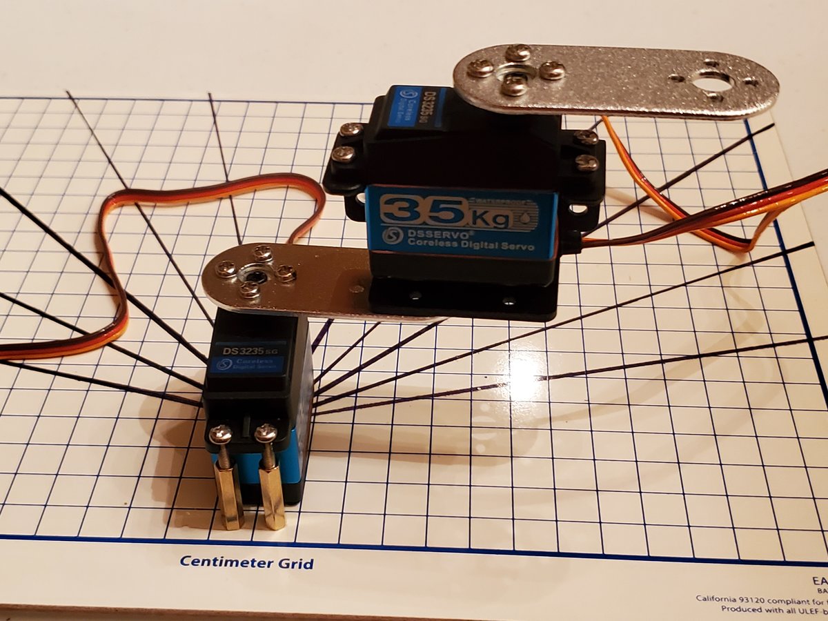
In this tutorial, we’ll learn how to draw the kinematic diagram for a two degree of freedom robotic arm.
Getting Started
A kinematic diagram shows how the links (the stiff parts of the robot) and joints (the servo motors or linear actuators) are connected when each joint is at an angle of 0 degrees (or in its 0 position in the case of a linear actuator).
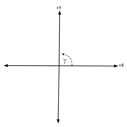
Remember that degree angles are measured in the counterclockwise direction, starting from the positive x-axis (see figure below).
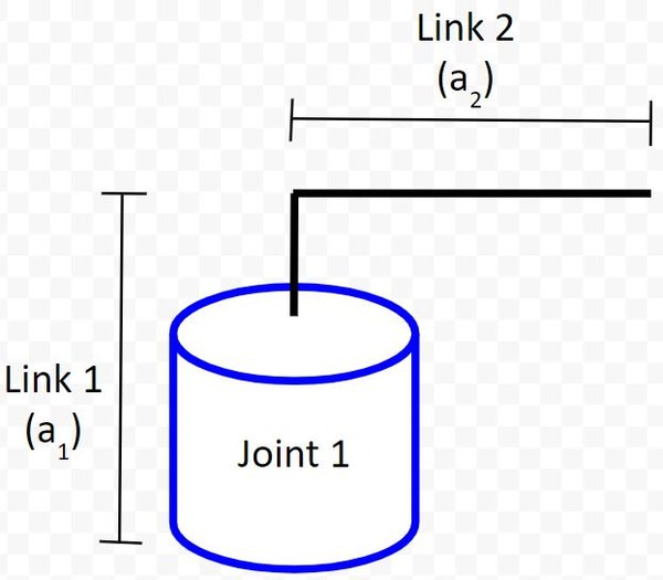
First, let’s start with creating our joint (revolute joint…i.e. the servo motor) as well as the two links. We’ll use the letter a to represent link lengths.
We now need to label the joint with the direction of positive rotation.
We use the right-hand rule whereby your thumb points in the direction of the rotation axis. In this case, your thumb will point upward (towards the ceiling) out of the servo horn. Your fingers will curl in the direction of positive rotation.
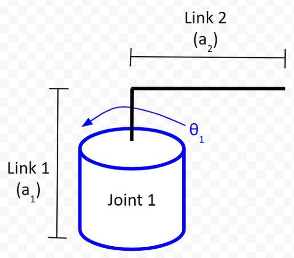
In this case, θ1 shows that the direction of positive rotation is counterclockwise if you are looking downward on the servo horn from above.
Add a Joint and a Link
Now, let’s add a joint (i.e. servo motor) to the end of link 2.
Remember, we will draw the diagram assuming that each joint is at 0 degrees.
We added another joint (i.e. a revolute joint because the motion entails revolution around a single axis) in the previous section.
Using the right-hand rule, take your thumb and point it in the direction of the axis of rotation (i.e. out of the top-center of the servo motor. Your fingers curl in the direction of positive rotation (in this case, counterclockwise…Note that clockwise rotation would be negative rotation).
Let’s draw the positive rotation.
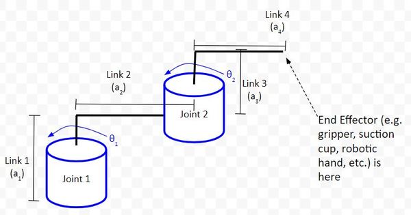
At this stage, our robotic arm (i.e. “manipulator”) has two degrees of freedom (2 DOF), corresponding to the two servo motors. The end effector would be the end of Link 4.
In robotics, an end effector is the part of the robot that has an effect on the outside world.
There are a lot of different types of robotic manipulator end effectors. An end effector could also be a gripper, suction cup, paint sprayer, etc.
References
Credit to Professor Angela Sodemann for teaching me this stuff. Dr. Sodemann is an excellent teacher (She runs a course on RoboGrok.com). On her YouTube channel, she provides some of the clearest explanations on robotics fundamentals you’ll ever hear.