
In this post, we’ll take a look at how to describe the rotation of a robot in a two-dimensional (2D) space.
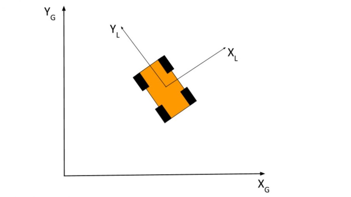
Consider the robot below. It’s moving around in a 2D coordinate frame. Its position in this coordinate frame can be described at any time by its x-coordinate and its y-coordinate.
We’ll call this coordinate frame the “global” reference frame because it defines the world that the robot is moving around in.
There is also another coordinate frame: the local reference frame. The local reference frame is the coordinate frame from the perspective of the robot (as opposed to the world). Local reference frame…robot reference frame…robot axes…all ways of saying the same thing.
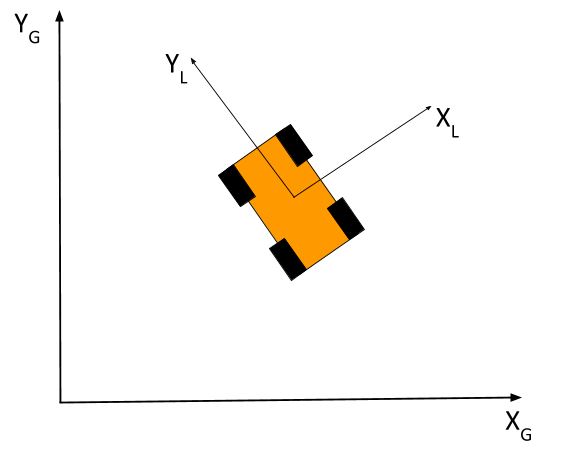
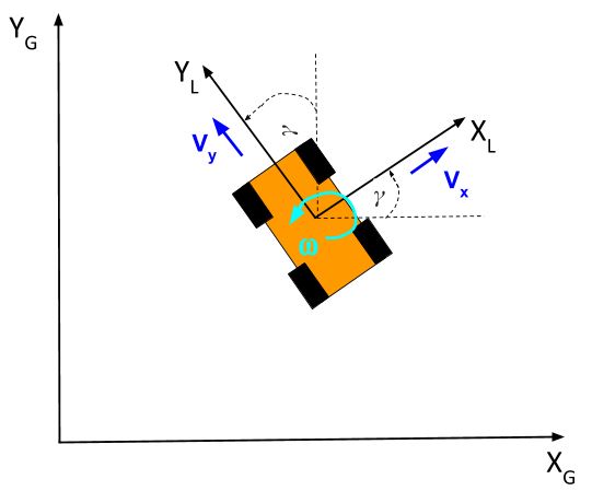
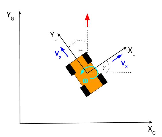
Let’s draw the y and x-axes of the local reference frame. The y-axis points towards the front of the robot, and the x-axis is perpendicular to the y-axis. The local reference frame is labeled with the subscript L, and the global reference frame is labeled with the subscript G.
Notice that the local reference frame is rotated at an angle from the global reference frame. We’ll call this angle γ.
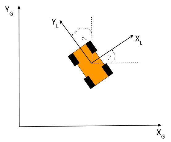
γ = Angular difference between the global x-axis and the local x-axis
You’ll also note that the angular difference between the global y-axis and the local y-axis is also equal to γ.
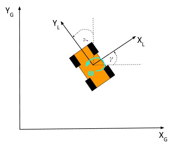
The rate at which the angle γ is changing (in the counterclockwise direction) is known as the angular velocity, and is often represented by the Greek letter ω. It’s the change in gamma divided by the change in time.
ω = (change in γ) / (change in time) = (γfinal – γinitial) / (tfinal – tinitial)
Now our robot isn’t very useful if all it does is rotate. Let’s suppose the robot is an omnidirectional robot…it can move in any direction. How do we describe the velocity of the robot?
Velocity is a measure of how fast something is moving in a particular direction. It is speed (e.g. miles per hour, meters per second, etc.) + direction.
The velocity of our 2D robot can be broken down into two components: velocity in the x-direction and velocity in the y-direction. The sum of both of those vectors defines the velocity of the robot.
Let’s draw the two velocity vectors right now from the perspective of the local reference frame.
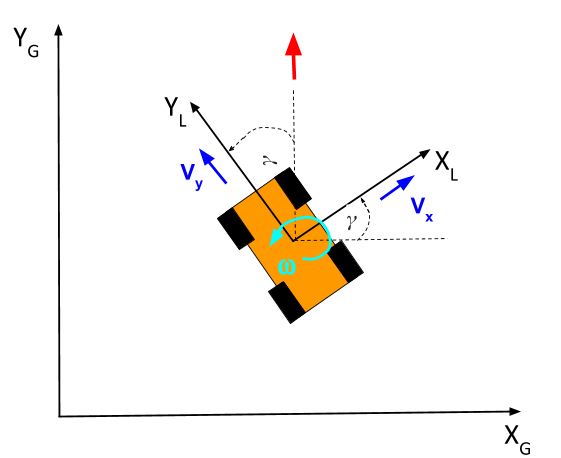
Suppose the robot is moving due north (as shown by the red arrow below) with respect to the global reference frame, while maintaining the same angle of rotation. In other words, the front of the robot is still pointed towards the “northwest,” while the robot is moving directly north, parallel to the global y-axis.
How do we calculate the magnitude of the robot’s velocity (i.e. its speed)?
We need to add the two velocity vectors together, using the head-to-tail method. The head of the first vector points to the tail of the next vector.
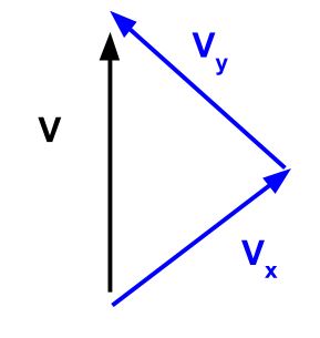
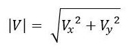
You probably notice that the angle between Vx and Vy is 90 degrees, so we can use the Pythagorean Theorem to calculate the speed (i.e. magnitude of the velocity) of the robot.
This velocity above is the velocity of the robot in the local reference frame. In other words, both Vx and Vy are parallel to the robot’s x-axis and y-axis respectively.
How do we convert these velocities in the local reference frame to velocities in the global reference frame? And why would we want to do that?
The reason for doing this conversion is so that we can know where in the world the robot will be at a particular time in the future. Just knowing the robot velocity vectors doesn’t help us. We need to know how the position of the robot is changing with respect to time in the global reference frame.
So let’s figure that out now. To solve this problem, we’ll need to use some trigonometry.
Let’s start from the graphic you are already familiar with.
Assume the center of the robot above is currently at the origin in the global reference frame.
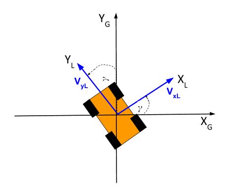
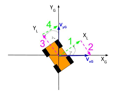
What is VxG, the velocity in the x-direction on the global reference frame? To answer that, we need to recognize that both the x and y components of the robot’s velocity in the local reference frame can be broken down into global reference frame components (i.e. the pink and green arrows below).
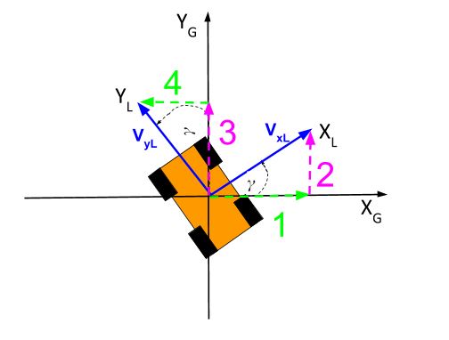
Let’s call the velocity of the robot in the global reference frame VxG and VyG. You can see from the above diagram of the pink and green vectors that:
VxG = (vector 1) – (vector 4) … Minus sign because vector 4 is pointing in the negative global x-axis direction
VyG = (vector 2) + (vector 3) … Plus sign because both vectors are pointing in the positive global y-axis direction
Now, how do we find vectors 1, 2, 3, and 4?
Do you remember the trigonometric ratios? Back in middle school, we used the acronym, SOHCAHTOA:
- Sine = Opposite / Hypotenuse (SOH)
- Cosine = Adjacent / Hypotenuse (CAH)
- Tangent = Opposite / Adjacent (TOA)
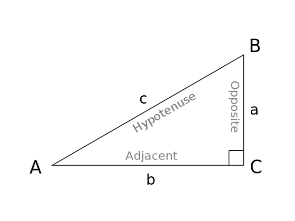
In the right triangle above: sin A = a/c; cos A = b/c; tan A = a/b.
Using these ratios as our guide, we get:
- vector 1 = VxL * cos(γ)
- vector 2 = VxL * sin(γ)
- vector 3 = VyL * cos(γ)
- vector 4 = VyL * sin(γ)
Plugging this information back in, we get the two equations that enable us to convert local velocities to global velocities.
- VxG = (VxL * cos(γ)) – (VyL * sin(γ))
- VyG = (VxL * sin(γ)) + (VyL * cos(γ))
If you’re familiar with linear algebra, you’ll notice that we can convert the system of equations above into matrix form:
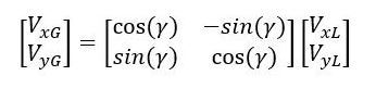
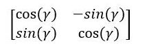
The matrix above with the cosines and sines is often referred to in robotics as the rotation matrix (or two-dimensional rotation matrix). It helps us convert either vectors or a point in the local reference frame to a vector or a point in the global reference frame.
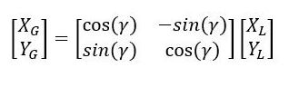
Here is how we convert a point in the local reference frame to a point in the global reference frame:
At this stage, you might now be wondering…how do I convert velocities in the global reference frame to velocities in the local reference frame? Say you were looking down on the robot from up above (i.e. aerial view) and had a radar gun that could measure the velocity of the robot…what would the velocity be from the perspective of the robot’s own x and y axes?
To answer that, let’s draw our local and global velocity vectors.
Now let’s write out equations for the local velocities in the x and y directions:
- VxL = (vector 1) + (vector 4) … Plus sign because both vectors are pointing in the positive local x-axis direction
- VyL = -(vector 2) + (vector 3) … Minus sign because vector 2 is pointing in the negative local y-axis direction
Using the trigonometric ratios we discussed earlier, we have the following equations:
- vector 1 = VxG * cos(γ)
- vector 2 = VXG * sin(γ)
- vector 3 = VyG * cos(γ)
- vector 4 = VyG * sin(γ)
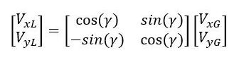
Plugging this information back in, we get the two equations that enable us to convert global velocities to local velocities.
- VxL = (VxG * cos(γ)) + (VyG * sin(γ))
- VyL = -(VxG * sin(γ)) + (VyG * cos(γ))
In matrix form, we have:
And there you have it. That’s how to describe the rotation of a robot in two dimensions.
In a future post, I’ll show you how to describe the rotation of a robot in three dimensions.