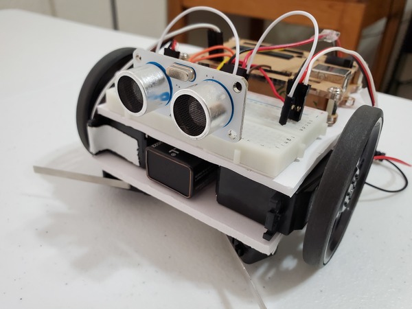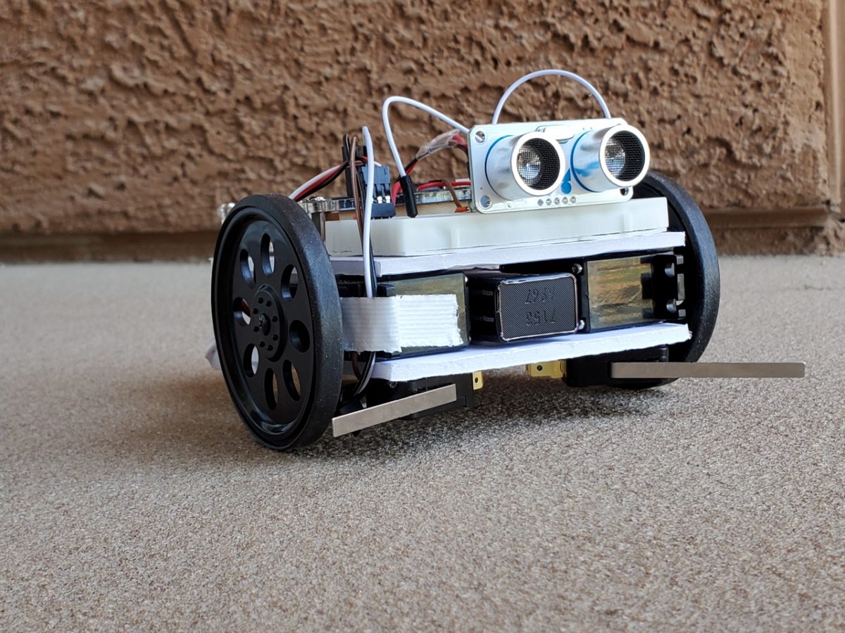
In this post, I’ll show you how to give your robot the ability to “see.” We’ll create an obstacle avoiding robot using Arduino and an ultrasonic sensor.
Shout out to the late Gordon McComb for this project idea. He is the author of an excellent book that I recommend buying if you’re getting started with robotics: How to Make a Robot.
An ultrasonic sensor works by producing high frequency sound waves and then measuring the time it takes for the sound to reflect back to the sensor. Objects that are closer to the robot reflect sound back faster than objects that are farther away. This data is then used by the robot to avoid running into objects. Bats use ultrasound in order to locate food and avoid obstacles inside dark caves. Dolphins emit ultrasound as well in order to detect and recognize objects.

Video
Here is a video of what we will build in this tutorial.
Requirements
Here are the requirements:
- Make a robot that avoids obstacles using an ultrasonic sensor.
You Will Need
The following components are used in this project. You will need:
Directions
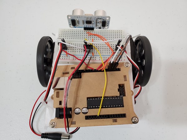
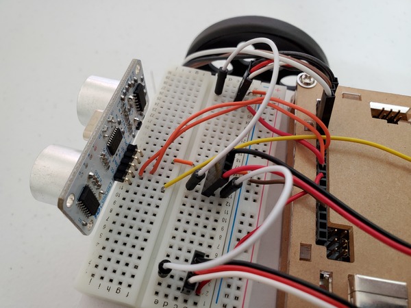
First, get your ultrasonic distance sensor and place the far left pin (the one labeled VCC, the supply voltage) into the solderless breadboard in cell j12.
Now, wire the ultrasonic sensor to the Arduino as follows. Remember that each cell in a single row of 5 cells on a solderless breadboard is electrically connected (e.g. j12 is connected to f12, g12, h12, and i12 electrically):
- VCC on the sensor connects to 5V on the Arduino
- Echo on the sensor connects to Digital Pin 8 on the Arduino
- Trig (stands for trigger) on the sensor connects to Digital Pin 7 on the Arduino
- GND (stands for Ground) on the sensor connects to ground on the solderless breadboard
Now, upload the following sketch to the Arduino to test the ultrasonic sensor.
/**
 *  This program tests the ultrasonic
 *  distance sensor
 *
 * @author Addison Sears-Collins
 * @version 1.0 2019-05-13
 */

/* Give a name to a constant value before
 * the program is compiled. The compiler will
 * replace references to Trigger and Echo with
 * 7 and 8, respectively, at compile time.
 * These defined constants don't take up
 * memory space on the Arduino.
 */
#define Trigger 7
#define Echo 8

/*
 *  This setup code is run only once, when
 *  Arudino is supplied with power.
 */
void setup(){

  // Set the baud rate to 9600. 9600 means that
  // the serial port is capable of transferring
  // a maximum of 9600 bits per second.
  Serial.begin(9600);

  // Define each pin as an input or output.
  pinMode(Echo, INPUT);
  pinMode(Trigger, OUTPUT);
}

void loop(){

  // Make the Trigger LOW (0 volts)
  // for 2 microseconds
  digitalWrite(Trigger, LOW);
  delayMicroseconds(2);

  // Emit high frequency 40kHz sound pulse
  // (i.e. pull the Trigger)
  // by making Trigger HIGH (5 volts)
  // for 10 microseconds
  digitalWrite(Trigger, HIGH);
  delayMicroseconds(10);
  digitalWrite(Trigger, LOW);

  // Detect a pulse on the Echo pin 8.
  // pulseIn() measures the time in
  // microseconds until the sound pulse
  // returns back to the sensor.
  int distance = pulseIn(Echo, HIGH);

  // Speed of sound is:
  // 13511.811023622 inches per second
  // 13511.811023622/10^6 inches per microsecond
  // 0.013511811 inches per microsecond
  // Taking the reciprocal, we have:
  // 74.00932414 microseconds per inch
  // Below, we convert microseconds to inches by
  // dividing by 74 and then dividing by 2
  // to account for the roundtrip time.
  distance = distance / 74 / 2;

  // Print the distance in inches
  Serial.println(distance);

  // Pause for 100 milliseconds
  delay(100);
}
As soon as uploading is finished and with the USB cable still connected to the Arduino, click on the green magnifying glass in the upper right of the IDE to open the Serial Monitor.
Make sure you have the following settings:
- Autoscroll: selected
- Line ending: No Line ending
- Baud: 9600 baud
Place any object in front of the sensor and move it back and forth. You should see the readings on the Serial Monitor change accordingly.
Now, close the Serial Monitor and upload the following sketch to the Arduino.
#include <Servo.h>

/**
 * This robot avoids obstacles
 * using an ultrasonic sensor.
 *
 * @author Addison Sears-Collins
 * @version 1.0 2019-05-13
 */

// Create two servo objects, one for each wheel
Servo right_servo;
Servo left_servo;

/* Give a name to a constant value before
 * the program is compiled. The compiler will
 * replace references to Trigger and Echo with
 * 7 and 8, respectively, at compile time.
 * These defined constants don't take up
 * memory space on the Arduino.
 */
#define Trigger 7
#define Echo 8

/*
 *  This setup code is run only once, when
 *  Arudino is supplied with power.
 */
void setup(){

  // Set the baud rate to 9600. 9600 means that
  // the serial port is capable of transferring
  // a maximum of 9600 bits per second.
  Serial.begin(9600);

  right_servo.attach(9);      // Right servo to pin 9
  left_servo.attach(10);      // Left servo to pin 10

  // Define each pin as an input or output.
  pinMode(Echo, INPUT);
  pinMode(Trigger, OUTPUT);

  // Initializes the pseudo-random number generator
  // Needed for the robot to wander around the room
  randomSeed(analogRead(3));

  delay(200);     // Pause 200 milliseconds
  go_forward();   // Go forward
}

/*
 * This is the main code that runs again and again while
 * the Arduino is connected to power.
 */
void loop(){
  int distance = doPing();

  // If obstacle <= 2 inches away
  if (distance >= 0 && distance <= 2) {
    Serial.println("Obstacle detected ahead");
    go_backwards();   // Move in reverse for 0.5 seconds
    delay(500);

    /* Go left or right to avoid the obstacle*/
    if (random(2) == 0) {  // Generates 0 or 1, randomly
      go_right();  // Turn right for one second
    }
    else {
      go_left();  // Turn left for one second
    }
    delay(1000);
    go_forward();  // Move forward
  }
  delay(50); // Wait 50 milliseconds before pinging again
}

/*
 * Returns the distance to the obstacle as an integer
 */
int doPing () {
  int distance = 0;
  int average = 0;

  // Grab four measurements of distance and calculate
  // the average.
  for (int i = 0; i < 4; i++) {

    // Make the Trigger LOW (0 volts)
    // for 2 microseconds
    digitalWrite(Trigger, LOW);
    delayMicroseconds(2);


    // Emit high frequency 40kHz sound pulse
    // (i.e. pull the Trigger)
    // by making Trigger HIGH (5 volts)
    // for 10 microseconds
    digitalWrite(Trigger, HIGH);
    delayMicroseconds(10);
    digitalWrite(Trigger, LOW);

    // Detect a pulse on the Echo pin 8.
    // pulseIn() measures the time in
    // microseconds until the sound pulse
    // returns back to the sensor.
    distance = pulseIn(Echo, HIGH);

    // Speed of sound is:
    // 13511.811023622 inches per second
    // 13511.811023622/10^6 inches per microsecond
    // 0.013511811 inches per microsecond
    // Taking the reciprocal, we have:
    // 74.00932414 microseconds per inch
    // Below, we convert microseconds to inches by
    // dividing by 74 and then dividing by 2
    // to account for the roundtrip time.
    distance = distance / 74 / 2;

    // Compute running sum
    average += distance;

    // Wait 10 milliseconds between pings
    delay(10);
  }

  // Return the average of the four distance
  // measurements
  return (average / 4);
}

/*
 *  Forwards, backwards, right, left, stop.
 */
void go_forward() {
  right_servo.write(0);
  left_servo.write(180);
}
void go_backwards() {
  right_servo.write(180);
  left_servo.write(0);
}
void go_right() {
  right_servo.write(180);
  left_servo.write(180);
}
void go_left() {
  right_servo.write(0);
  left_servo.write(0);
}
void stop_all() {
  right_servo.write(90);
  left_servo.write(90);
}
Disconnect the USB cable from the Arduino, and place the Arduino on the floor.
Turn on the servos:
- a13 to e3 = left servo ON
- e13 to e28 = right servo ON
Then plug in the Arduino’s power.
Watch the Obstacle Avoiding Robot move!