Obstacle Avoiding Robot Using a DC Motor and Arduino

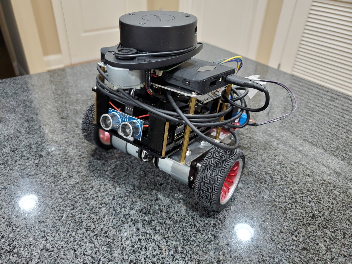
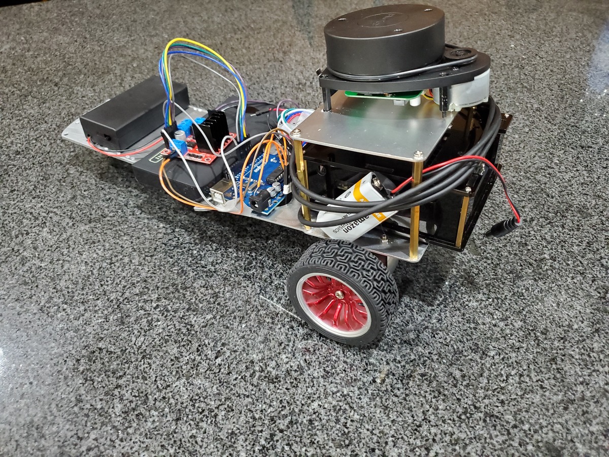
In this tutorial, I will show you my setup for an obstacle avoiding robot that has two DC motors and uses Arduino as its “brain”.

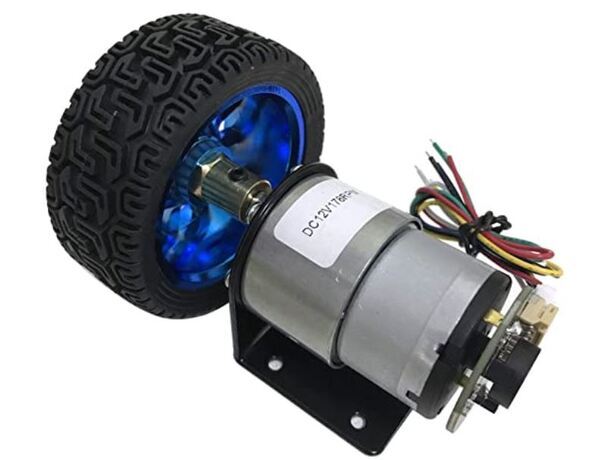
Here is the motor I am working with, but you can use any motor that looks like this one.

1_dc_motor_encoder_wheels-1

Real-World Applications

This project has a number of real-world applications: 

  • Indoor Delivery Robots
  • Robot Vacuums
  • Factories

Prerequisites

You Will Need

In addition to the parts listed in the article I linked to in the Prerequisites, you will need the following components (#ad).

Disclosure (#ad): As an Amazon Associate I earn from qualifying purchases.

Set Up the HC-SR04 Ultrasonic Distance Sensor

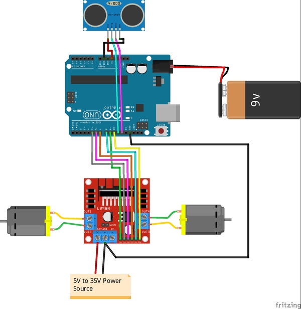
The first thing we need to do is set up the hardware. Here is the wiring diagram:

hcsr04_ultrasonic_distance_sensor_bb
  • VCC on the sensor connects to 5V on the Arduino
  • Echo on the sensor connects to Digital Pin 12 on the Arduino
  • Trig (stands for trigger) on the sensor connects to Digital Pin 11 on the Arduino
  • GND (stands for Ground) on the sensor connects to GND on the Arduino

Test the Ultrasonic Distance Sensor

Now, upload the following sketch to the Arduino to test the ultrasonic sensor. I named my program test_ultrasonic_distance_sensor.ino.

/**
 *  This program tests the ultrasonic
 *  distance sensor
 * 
 * @author Addison Sears-Collins
 * @version 2.0 2021-04-11
 */
 
/* Give a name to a constant value before
 * the program is compiled. The compiler will 
 * replace references to Trigger and Echo with 
 * 11 and 12, respectively, at compile time.
 * These defined constants don't take up 
 * memory space on the Arduino.
 */
#define Trigger 11
#define Echo 12
 
/*   
 *  This setup code is run only once, when 
 *  Arudino is supplied with power.
 */
void setup(){
 
  // Set the baud rate to 9600. 9600 means that 
  // the serial port is capable of transferring 
  // a maximum of 9600 bits per second.
  Serial.begin(9600);
 
  // Define each pin as an input or output.
  pinMode(Echo, INPUT);
  pinMode(Trigger, OUTPUT);
}
 
void loop(){
 
  // Make the Trigger LOW (0 volts) 
  // for 2 microseconds
  digitalWrite(Trigger, LOW);
  delayMicroseconds(2);
 
  // Emit high frequency 40kHz sound pulse
  // (i.e. pull the Trigger) 
  // by making Trigger HIGH (5 volts) 
  // for 10 microseconds
  digitalWrite(Trigger, HIGH);
  delayMicroseconds(10);
  digitalWrite(Trigger, LOW); 
 
  // Detect a pulse on the Echo pin 8. 
  // pulseIn() measures the time in 
  // microseconds until the sound pulse
  // returns back to the sensor.
  int distance = pulseIn(Echo, HIGH);
 
  // Speed of sound is:
  // 13511.811023622 inches per second
  // 13511.811023622/10^6 inches per microsecond
  // 0.013511811 inches per microsecond
  // Taking the reciprocal, we have:
  // 74.00932414 microseconds per inch 
  // Below, we convert microseconds to inches by 
  // dividing by 74 and then dividing by 2
  // to account for the roundtrip time.
  distance = distance / 74 / 2;
 
  // Print the distance in inches
  Serial.println(distance);
 
  // Pause for 100 milliseconds
  delay(100);
}

As soon as uploading is finished and with the USB cable still connected to the Arduino, click on the green magnifying glass in the upper right of the IDE to open the Serial Monitor.

Make sure you have the following settings:

  • Autoscroll: selected
  • Line ending: No Line ending
  • Baud: 9600 baud

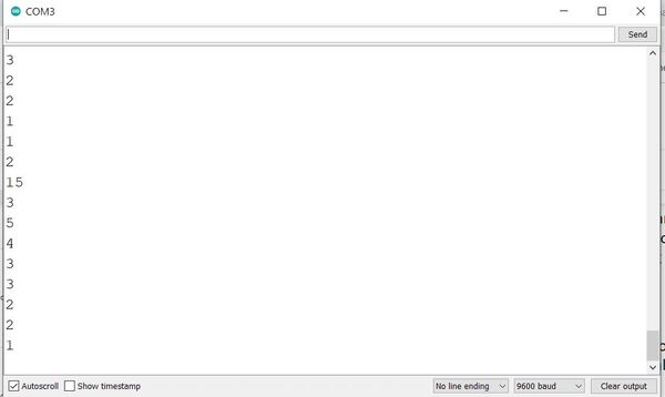
Place any object in front of the sensor and move it back and forth. You should see the readings on the Serial Monitor change accordingly.

1_test_ultrasonic_sensor

Code for Obstacle Avoidance

Now, upload the following sketch to your Arduino. I named my program obstacle_avoiding_robot_l298n.ino

/**
 * This robot avoids obstacles 
 * using an ultrasonic sensor.
 * 
 * @author Addison Sears-Collins
 * @version 1.0 2021-04-11
 */
 
// Motor A connections
const int enA = 9;
const int in1 = 5;
const int in2 = 6;

// Motor B connections
const int enB = 10;
const int in3 = 7;
const int in4 = 8;

// Set the speed (0 = off and 255 = max speed)
// If your wheels are not moving, check your connections,
// or increase the speed.
const int motorSpeed = 80;
 
/* Give a name to a constant value before
 * the program is compiled. The compiler will 
 * replace references to Trigger and Echo with 
 * 11 and 12, respectively, at compile time.
 * These defined constants don't take up 
 * memory space on the Arduino.
 */
#define Trigger 11
#define Echo 12
 
/*   
 *  This setup code is run only once, when 
 *  Arudino is supplied with power.
 */
void setup(){
   
  // Set the baud rate to 9600. 9600 means that 
  // the serial port is capable of transferring 
  // a maximum of 9600 bits per second.
  //Serial.begin(9600);
 
  // Motor control pins are outputs
  pinMode(enA, OUTPUT);
  pinMode(enB, OUTPUT);
  pinMode(in1, OUTPUT);
  pinMode(in2, OUTPUT);
  pinMode(in3, OUTPUT);
  pinMode(in4, OUTPUT);

  // Turn off motors - Initial state
  digitalWrite(in1, LOW);
  digitalWrite(in2, LOW);
  digitalWrite(in3, LOW);
  digitalWrite(in4, LOW);

  // Set the motor speed
  analogWrite(enA, motorSpeed); 
  analogWrite(enB, motorSpeed); 
 
  // Define each pin as an input or output.
  pinMode(Echo, INPUT);
  pinMode(Trigger, OUTPUT);
 
  // Initializes the pseudo-random number generator
  // Needed for the robot to wander around the room
  randomSeed(analogRead(3));
 
  delay(200);     // Pause 200 milliseconds               
  go_forward();   // Go forward
}
 
/*
 * This is the main code that runs again and again while
 * the Arduino is connected to power.
 */
void loop(){
  int distance = doPing();
 
  // If obstacle <= 16 inches away
  if (distance >= 0 && distance <= 16) {  
      
    //Serial.println("Obstacle detected ahead");  
    go_backwards();   // Move in reverse
    delay(2000);
 
    /* Go left or right to avoid the obstacle*/
    if (random(2) == 0) {  // Generates 0 or 1, randomly        
      go_right();  // Turn right
    }
    else {
      go_left();  // Turn left
    }
    delay(3000);
    go_forward();  // Move forward
  }
  delay(50); // Wait 50 milliseconds before pinging again
}
 
/*
 * Returns the distance to the obstacle as an integer
 */
int doPing () {
  int distance = 0;
  int average = 0;
 
  // Grab four measurements of distance and calculate
  // the average.
  for (int i = 0; i < 4; i++) {
 
    // Make the Trigger LOW (0 volts) 
    // for 2 microseconds
    digitalWrite(Trigger, LOW);
    delayMicroseconds(2);
 
     
    // Emit high frequency 40kHz sound pulse
    // (i.e. pull the Trigger) 
    // by making Trigger HIGH (5 volts) 
    // for 10 microseconds
    digitalWrite(Trigger, HIGH);
    delayMicroseconds(10);
    digitalWrite(Trigger, LOW);
      
    // Detect a pulse on the Echo pin 8. 
    // pulseIn() measures the time in 
    // microseconds until the sound pulse
    // returns back to the sensor.    
    distance = pulseIn(Echo, HIGH);
 
    // Speed of sound is:
    // 13511.811023622 inches per second
    // 13511.811023622/10^6 inches per microsecond
    // 0.013511811 inches per microsecond
    // Taking the reciprocal, we have:
    // 74.00932414 microseconds per inch 
    // Below, we convert microseconds to inches by 
    // dividing by 74 and then dividing by 2
    // to account for the roundtrip time.
    distance = distance / 74 / 2;
 
    // Compute running sum
    average += distance;
 
    // Wait 10 milliseconds between pings
    delay(10);
  }
 
  // Return the average of the four distance 
  // measurements
  return (average / 4);
}
 
/*   
 *  Forwards, backwards, right, left, stop.
 */
void go_forward() {
  digitalWrite(in1, HIGH);
  digitalWrite(in2, LOW);
  digitalWrite(in3, HIGH);
  digitalWrite(in4, LOW);
}
void go_backwards() {
  digitalWrite(in1, LOW);
  digitalWrite(in2, HIGH);
  digitalWrite(in3, LOW);
  digitalWrite(in4, HIGH);
}
void go_right() {
  digitalWrite(in1, HIGH);
  digitalWrite(in2, LOW);
  digitalWrite(in3, LOW);
  digitalWrite(in4, HIGH);
}
void go_left() {
  digitalWrite(in1, LOW);
  digitalWrite(in2, HIGH);
  digitalWrite(in3, HIGH);
  digitalWrite(in4, LOW);
}
void stop_all() {
  digitalWrite(in1, LOW);
  digitalWrite(in2, LOW);
  digitalWrite(in3, LOW);
  digitalWrite(in4, LOW);
}

Disconnect the USB cable from the Arduino.

Place your robot on the floor.

Turn the power ON for the motors.

Plug in the Arduino’s power.

Watch the Obstacle Avoiding Robot move!

If your wheels are not moving, check your connections, or increase the speed.

Related Articles

How to Connect DC Motors to Arduino and the L298N

In this tutorial, we learn how to connect DC motors to Arduino and the L298N motor driver.  

Here is the motor we will work with, but you can use any motor that looks like this one.

1_dc_motor_encoder_wheels-1

Prerequisites

You have the Arduino IDE (Integrated Development Environment) installed on your PC (Windows, MacOS, or Linux).

You Will Need

This section is the complete list of components you will need for this project (#ad).

OR

  • Self-Balancing Car Kit (which includes everything above and more…Elegoo and Osoyoo are good brands you can find on Amazon.com)

I also bought the following:

Disclosure (#ad): As an Amazon Associate I earn from qualifying purchases.

Set Up the Hardware

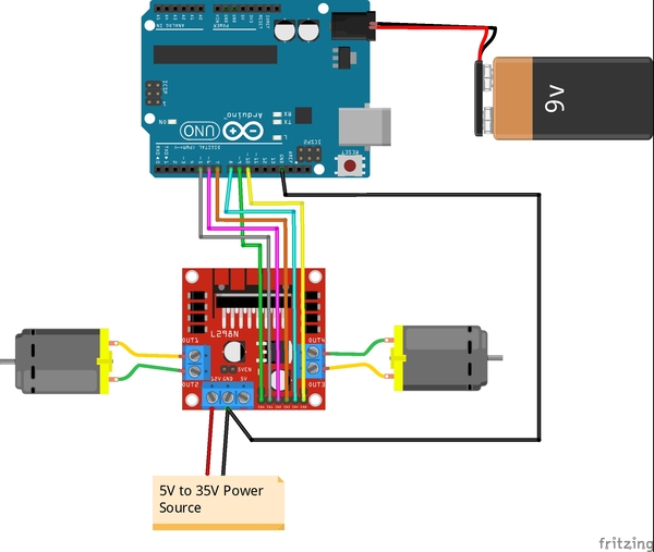
The first thing we need to do is set up the hardware. Below is the wiring diagram, and here is the pdf version so you can see the pin numbers better:

connect_dc_motor_l298n_bb

On my motors, the outer pins are the ones that drive the motors. These pins need to be connected to the L298N OUT1-OUT4 pins.

Remove the two black jumpers that are on the board that cover the ENA and ENB pins. Do not remove the other jumper that is near the power input pins.

Write the Code

Now let’s write the code. You will need to:

  • Load this code to your Arduino from your PC.
  • Remove the Arduino from your PC.
  • Turn on your Arduino using the 9V battery.
/*
 * Author: Automatic Addison
 * Website: https://automaticaddison.com
 * Description: Controls the speed and direction of two DC motors.
 */

// Motor A connections
const int enA = 9;
const int in1 = 5;
const int in2 = 6;

// Motor B connections
const int enB = 10; 
const int in3 = 7;
const int in4 = 8;

// Set the speed (0 = off and 255 = max speed)
const int motorSpeed = 128;

void setup() {
  
  // Motor control pins are outputs
  pinMode(enA, OUTPUT);
  pinMode(enB, OUTPUT);
  pinMode(in1, OUTPUT);
  pinMode(in2, OUTPUT);
  pinMode(in3, OUTPUT);
  pinMode(in4, OUTPUT);

  // Turn off motors - Initial state
  digitalWrite(in1, LOW);
  digitalWrite(in2, LOW);
  digitalWrite(in3, LOW);
  digitalWrite(in4, LOW);

  // Set the motor speed
  analogWrite(enA, motorSpeed); 
  analogWrite(enB, motorSpeed); 
}

void loop() {

  // Go forwards
  go_forward();
  delay(3000);

  // Go backwards
  go_backwards();
  delay(3000);

  // Go right
  go_right();
  delay(3000);

  // Go left
  go_left();
  delay(3000);

  // Stop
  stop_all();
  delay(3000);
}

/*   
 *  Forwards, backwards, right, left, stop.
 */
void go_forward() {
  digitalWrite(in1, HIGH);
  digitalWrite(in2, LOW);
  digitalWrite(in3, HIGH);
  digitalWrite(in4, LOW);
}
void go_backwards() {
  digitalWrite(in1, LOW);
  digitalWrite(in2, HIGH);
  digitalWrite(in3, LOW);
  digitalWrite(in4, HIGH);
}
void go_right() {
  digitalWrite(in1, HIGH);
  digitalWrite(in2, LOW);
  digitalWrite(in3, LOW);
  digitalWrite(in4, HIGH);
}
void go_left() {
  digitalWrite(in1, LOW);
  digitalWrite(in2, HIGH);
  digitalWrite(in3, HIGH);
  digitalWrite(in4, LOW);
}
void stop_all() {
  digitalWrite(in1, LOW);
  digitalWrite(in2, LOW);
  digitalWrite(in3, LOW);
  digitalWrite(in4, LOW);
}

Run the Code

When you run this code, you will see your motors move forwards, backwards, right turn, left turn, and then stop. If your motors don’t do this exact sequence, consider switching the position of the wire connections that both motors have to the L298N.

References

How to Calculate the Velocity of a DC Motor With Encoder

In this tutorial, we learn how to calculate the angular velocity (magnitude and direction of rotation in radians per second) of a DC motor with a built-in encoder.  

Here is the motor we will work with, but you can use any motor that looks like this one.

1_dc_motor_encoder_wheels-1

Real-World Applications

Knowing the angular velocity of wheels on a robot helps us calculate how fast the robot is moving (i.e. speed) as well as the distance a robot has traveled in a given unit of time. This information is important for helping us determine where a robot is in a particular environment (i.e. odometry).

Prerequisites

You Will Need

This section is the complete list of components you will need for this project (#ad).

2 x JGB37-520B DC Motor with Encoder OR 2 x JGB37-520B DC 6V 12V Micro Geared Motor With Encoder and Wheel Kit (includes wheels)

Arduino Uno r3

OR

Self-Balancing Car Kit (which includes everything above and more…Elegoo and Osoyoo are good brands you can find on Amazon.com)

Disclosure (#ad): As an Amazon Associate I earn from qualifying purchases.

Set Up the Hardware

The first thing we need to do is set up the hardware.

Here is the wiring diagram:

jgb37_dc_motor_with_encoder-2
  • The Ground pin of the motor connects to GND of the Arduino.
  • Encoder A (sometimes labeled C1) of the motor connects to pin 2 of the Arduino. Pin 2 of the Arduino will record every time there is a rising digital signal from Encoder A.
  • Encoder B (sometimes labeled C2) of the motor connects to pin 4 of the Arduino. The signal that is read off pin 4 on the Arduino will determine if the motor is moving forward or in reverse.
  • The VCC pin of the motor connects to the 5V pin of the Arduino. This pin is responsible for providing power to the encoder.
  • For this project, you don’t need to connect the motor pins (+ and – terminals) to anything since you will be turning the motor manually with your hand. 

Write and Load the Code to Calculate Angular Velocity

Now we’re ready to calculate the angular velocity of the wheel. 

Open the Arduino IDE, and write the following program. The name of my program is calculate_angular_velocity.ino.

/*
 * Author: Automatic Addison
 * Website: https://automaticaddison.com
 * Description: Calculate the angular velocity in radians/second of a DC motor
 * with a built-in encoder (forward = positive; reverse = negative) 
 */

// Motor encoder output pulses per 360 degree revolution (measured manually)
#define ENC_COUNT_REV 620

// Encoder output to Arduino Interrupt pin. Tracks the pulse count.
#define ENC_IN_RIGHT_A 2

// Other encoder output to Arduino to keep track of wheel direction
// Tracks the direction of rotation.
#define ENC_IN_RIGHT_B 4

// True = Forward; False = Reverse
boolean Direction_right = true;

// Keep track of the number of right wheel pulses
volatile long right_wheel_pulse_count = 0;

// One-second interval for measurements
int interval = 1000;
 
// Counters for milliseconds during interval
long previousMillis = 0;
long currentMillis = 0;

// Variable for RPM measuerment
float rpm_right = 0;

// Variable for angular velocity measurement
float ang_velocity_right = 0;
float ang_velocity_right_deg = 0;

const float rpm_to_radians = 0.10471975512;
const float rad_to_deg = 57.29578;

void setup() {

  // Open the serial port at 9600 bps
  Serial.begin(9600); 

  // Set pin states of the encoder
  pinMode(ENC_IN_RIGHT_A , INPUT_PULLUP);
  pinMode(ENC_IN_RIGHT_B , INPUT);

  // Every time the pin goes high, this is a pulse
  attachInterrupt(digitalPinToInterrupt(ENC_IN_RIGHT_A), right_wheel_pulse, RISING);
  
}

void loop() {

  // Record the time
  currentMillis = millis();

  // If one second has passed, print the number of pulses
  if (currentMillis - previousMillis > interval) {

    previousMillis = currentMillis;

    // Calculate revolutions per minute
    rpm_right = (float)(right_wheel_pulse_count * 60 / ENC_COUNT_REV);
    ang_velocity_right = rpm_right * rpm_to_radians;   
    ang_velocity_right_deg = ang_velocity_right * rad_to_deg;
    
    Serial.print(" Pulses: ");
    Serial.println(right_wheel_pulse_count);
    Serial.print(" Speed: ");
    Serial.print(rpm_right);
    Serial.println(" RPM");
    Serial.print(" Angular Velocity: ");
    Serial.print(rpm_right);
    Serial.print(" rad per second");
    Serial.print("\t");
    Serial.print(ang_velocity_right_deg);
    Serial.println(" deg per second");
    Serial.println();

    right_wheel_pulse_count = 0;
  
  }
}

// Increment the number of pulses by 1
void right_wheel_pulse() {
  
  // Read the value for the encoder for the right wheel
  int val = digitalRead(ENC_IN_RIGHT_B);

  if(val == LOW) {
    Direction_right = false; // Reverse
  }
  else {
    Direction_right = true; // Forward
  }
  
  if (Direction_right) {
    right_wheel_pulse_count++;
  }
  else {
    right_wheel_pulse_count--;
  }
}

Compile the code by clicking the green checkmark in the upper-left of the IDE window.

Connect the Arduino board to your personal computer using the USB cord.

Load the code we just wrote to your Arduino board.

Open the Serial Monitor.

Here is the output when I rotate the motor forward:

fw_vel

Here is the output when I rotate the motor in reverse.

rev_vel

Calculating Linear Velocity

Now that you know how to calculate the angular velocity of a wheel, you can calculate the linear velocity of that wheel if you know it’s radius. Here is the equation:

(Linear Velocity in meters per second) = (Radius of the wheel in meters) * (Angular Velocity in radians per second)

This equation above is commonly written as:

v = r * ω

That’s it. Keep building!