Video Transcript
In this video, we’ll set up the Adafruit BNO055 Absolute Orientation Sensor from scratch, step-by-step.
The BNO055 is actually three sensors in one device. It includes an accelerometer to measure acceleration forces, a gyroscope that uses Earth’s gravity to help determine orientation, and a magnetometer that measures magnetism. Typical applications of this sensor include navigation, robotics, fitness, augmented reality, and tablet computers.
By the end of this video, you will have all of the hardware and software of the BNO055 sensor set up and ready to go so you can measure the roll, pitch, and yaw of an aerial electronic device, such as a drone.
Ok, let’s get started. Feel free to pause the video at any time as you follow along with me.
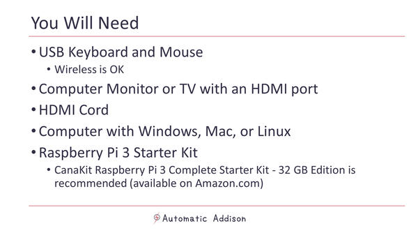
You will need:
- Arduino Uno
- BNO055 IMU Board
- Heat Insulation Silicone Repair Mat
- 40-Watt Soldering Station
- 63-37 Tin Lead Rosin core solder wire
- USB cord (comes with the Arduino Uno above)
- Solderless Breadboard
- Damp sponge
- USB Mini Desktop Office Fan
- Male to male jumper wires
To begin, get your BNO055 IMU board, the header strip, and the solderless breadboard. Lay them out on a table.
Prepare the header strip by cutting it to an appropriate length and placing it into the breadboard. You want a piece with 4 pins and a piece with 6 pins so that they can fit into the holes on the BNO055 board.
Place the long pins down into the solderless breadboard.
Next place the BNO055 board on top of the pins.
We will now solder all of the pins to the BNO055 in order to solidify electrical contact:
- Gather all the materials presented earlier in the video, and lay them out on a table.
- If you have safety glasses and latex gloves, put them on. Eyeglasses are fine.
- Turn on the USB fan for ventilation, in order to avoid breathing in the soldering smoke.
- Turn on the soldering iron to the 4 heat setting.
- Lay your damp sponge in the center of the silicon mat.
- Once the iron is hot, tin the tip by adding a little bit of solder to cover the tip.
- Now wipe the tip off on the damp sponge to remove all but a thin layer of solder to help the tip last longer and to facilitate the transfer of heat from the soldering iron to the joint.
- Place the tip of the soldering iron to the joint, where the header pin and board meet, to heat it up.
- Feed a small amount of solder to the joint and remove the soldering iron after 2 seconds in order to not damage the board. Do this for all the pins in the BNO055.
- OK, we are done soldering. With the soldering iron hot, wipe it off on a damp sponge.
- Turn off the soldering iron and clean everything up.
With the BNO055 all cooled off, we need to wire the BNO055 to the Arduino Uno using the solderless breadboard. Here are the connections we need to make.
- Connect Vin of the BNO055 to the power supply of 5V on the Arduino
- Connect GND of the BNO055 to GND on the Arduino
- Connect the SDA pin of the BNO055 to the SDA pin of the Arduino, which is A4.
- Connect the SCL pin of the BNO055 to the SCL pin of the Arduino, which is A5.
Next, we attach the Arduino Uno to the USB port on our main desktop computer.
Now, on our desktop computer, we open Arduino.
We navigate to the Library manager and install two libraries:
- The Adafruit Unified Sensor system library to retrieve orientation data in a standard data format, and…
- The Adafruit_BNO055 driver, which supports reading raw sensor data.
Now, go to File -> Examples -> Adafruit BNO055, and click sensorapi. The Arduino sketch that pops up is a demo that will help us test the BNO055.
First double check the Arduino is properly connected to your desktop computer by going to Tools -> Port. Make sure the Arduino/Genuino Uno has a checkmark next to it.
Now, let’s run the demo. Save the sensorapi sketch, compile it by clicking the checkmark, and upload it to the Arduino by clicking the right arrow button.
Once it is finished uploading, open the Serial monitor by clicking the magnifying glass in the upper right corner. We see the x, y, and z orientation data flowing in real-time.
However, we want Roll, Pitch, Yaw data and not X, Y, Z. So we need to change X, Y, and Z to Roll, Pitch, Yaw.
I’m going to use this website to refresh myself what roll, pitch, and yaw are.
Yaw is movement from side to side. Like when you shake your head “no.”
Pitch is movement up and down. Like when you nod your head “yes.”
Roll is movement from left to right. Like when you tilt your head from side to side.
Ok, let’s start the sensorapi program up again and see what happens to the X, Y, and Z values when we move the BNO055 board around, in different orientations. The front of the BNO055 board is labeled BNO055.
We rotate the BNO055 board around to 90 degrees yaw in the East direction. I see the X value changes. Then we roll the board to the right. The Z value changes. I then pitch the board by pointing the board straight up at the sky. The Y value changes. So there we have it. Yaw is X, Roll is Z, and Pitch is Y.
We go to the sensorapi code and modify it accordingly so that we use the terms Yaw, Roll, and Pitch, instead of X, Z, and Y, respectively.
Let’s compile and upload the program again to make sure everything is working properly. Here is the output of the Serial monitor.
Ok. That completes this video. You are now ready to use your BNO055.