Robots are now being used to explore some of the most dangerous and inhospitable places on Earth, and even beyond.
In this blog post, we will cover some of the ways that robots are helping to explore the unknown. We will also take a look at some of the challenges that need to be overcome in order to develop robots that can safely and effectively explore even the most extreme environments.
Robots in Space
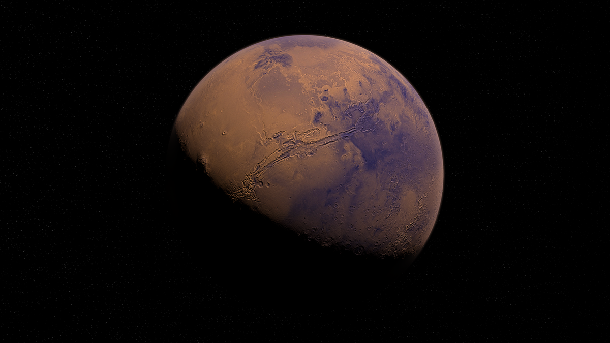
One of the most exciting areas of robotic exploration is space. Robots have been used to explore the Moon, Mars, and other planets in our solar system. They have also been used to repair and service satellites in orbit.
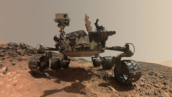
One of the most famous robotic space explorers is the Curiosity rover, which landed on Mars in 2012. Curiosity has been exploring the Gale Crater on Mars for over a decade, and has made many important discoveries about the planet’s past and present environment.
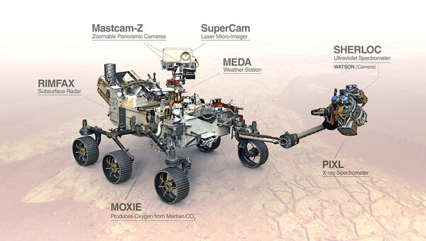
Another notable robotic space explorer is the Perseverance rover, which landed on Mars in 2021. Perseverance is tasked with collecting samples from Mars that will be returned to Earth for analysis. This could help us to learn even more about the Red Planet and its potential for habitability.
Robots in the Deep Sea
Robots are also being used to explore the deep sea. The deep sea is one of the least explored places on Earth, and robots are helping us to learn more about its unique ecosystems and biodiversity.
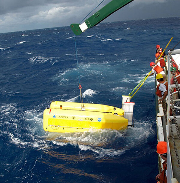
One example of a robotic deep sea explorer is the remotely operated vehicle (ROV) Nereus. Nereus is capable of diving to depths of over 10,000 meters, and has been used to explore the Mariana Trench, the deepest point in the ocean.
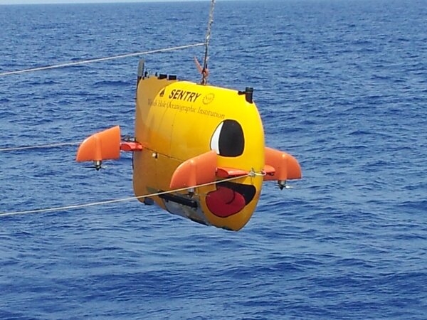
Another example of a robotic deep sea explorer is the autonomous underwater vehicle (AUV) Sentry. Sentry is capable of operating independently for months at a time, and has been used to map the seafloor and collect data on marine life.
Robots in Other Extreme Environments
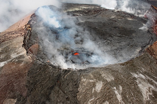
Robots are also being used to explore other extreme environments on Earth, such as volcanoes, caves, and glaciers. These environments can be dangerous for humans to explore, but robots can safely navigate them and collect data.
One example of a robotic extreme environment explorer is the robot submarine Nereid Under Ice (NUI). NUI is a hybrid remotely operated vehicle (ROV) developed by the Woods Hole Oceanographic Institution (WHOI). It is designed to explore and sample under-ice environments, which are difficult to access using traditional methods.

NUI is equipped with a high-definition video camera, a 7-function electro-hydraulic manipulator arm, and a range of acoustic, chemical, and biological sensors. It can operate in water depths of up to 4,000 meters and can be deployed from icebreakers or research vessels.
Challenges and Future Directions
There are still a number of challenges that need to be overcome in order to develop robots that can safely and effectively explore even the most extreme environments.
One challenge is developing robots that are powered by long-lasting batteries. This is especially important for robots that need to operate in remote or inaccessible areas.
Another challenge is developing robots that can withstand harsh environmental conditions. For example, robots that explore volcanoes need to be able to withstand high temperatures and toxic gases.
Finally, robots need to be equipped with sensors and artificial intelligence (AI) that allow them to perceive their surroundings and make decisions autonomously. This is especially important for robots that need to operate in dangerous or unpredictable environments.
Additional Thoughts
Here are some additional thoughts on how robots are helping us to explore the unknown:
- Robots are being used to explore the human body. For example, robotic surgical systems allow surgeons to perform complex procedures with greater precision and accuracy than would be possible with traditional methods.
- Robots are being used to explore the past. For example, archaeologists are using robots to excavate ancient ruins and search for lost artifacts.
The possibilities for robotic exploration are endless. As robots become more capable and sophisticated, we can expect them to help us to learn more about the world around us.
Keep building!