Motors are what enable robots to move and do things. Without motors, robots are just big pieces of metal and plastic that can’t move.
The simplest type of motor is the direct current (DC) motor. This type of motor spins around and around in one direction, rotating 360 degrees. It only stops rotating when it is disconnected from a power source. DC motors are common in wheeled robots.
Another type of motor is known as the servo motor (“servo”). Instead of rotating continuously for 360 degrees in one direction, servo motors move to specific angles, typically anything between 0 and 180 degrees. Servo motors are common in robotics. You will see them in all types of applications where a motor needs to move a part of the robot to a specific position. Examples include robot arms, hands, legs, and humanoid robots. NASA’s Robonaut 2, for example, has a total of 54 servo motors which are used to move the robot’s joints, head, and other body parts.
In this post, I will explain how servos work, and then we will get our hands dirty by powering up our Arduino and using it to control a servo.
How Servos Work
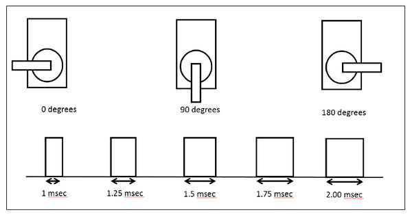
Servos work by receiving electrical signals. The length of this signal controls the angle the motor turns…the longer the signal, the greater the motor will turn. This process is known as pulse-width-modulation because the width (i.e. duration) of the electrical pulse modulates (modifies) the motor’s angle of rotation. Here is what that looks like:
Requirements
Here are the requirements:
- Control a servo motor’s angle of rotation.
You Will Need
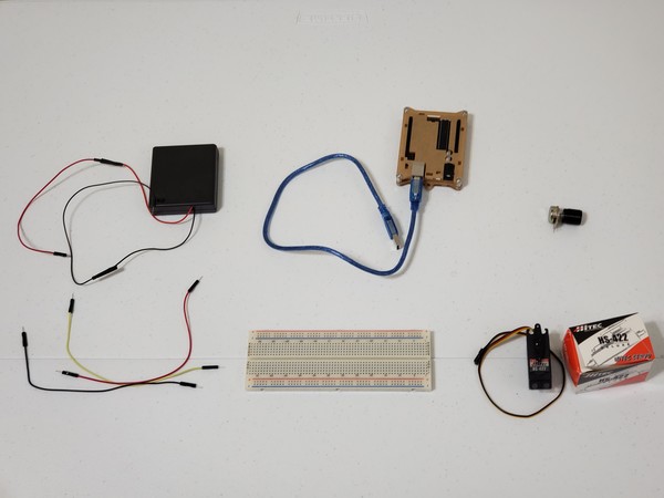
The following components are used in this project. You will need:
- Arduino (sends the electrical pulses to the servo to tell it how much to rotate)
- Servo Motor (eg. Hitec HS-422 model)
- 10k Ohm Potentiometer
- 4xAA Battery Holder with On Off Switch
- 4 AA Batteries
- Solderless Breadboard
- Male-to-Male Jumper Wires
Directions
Control a Servo Using Arduino’s Power Supply
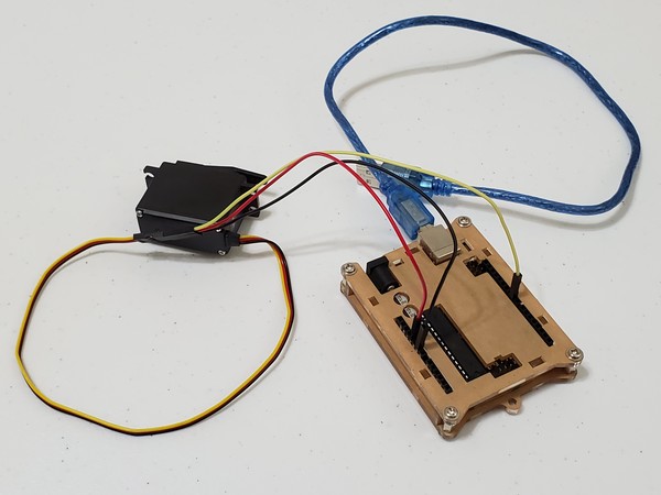
Here is the hardware we need to set up:
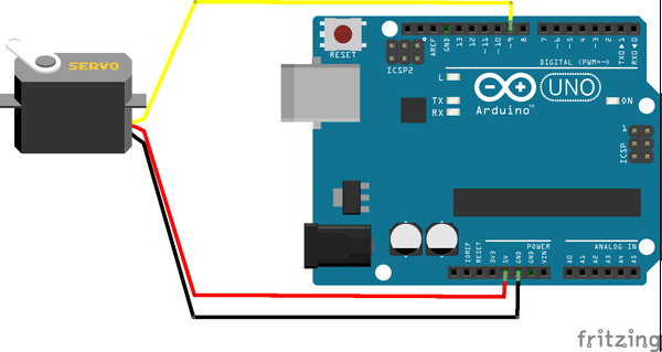
Connect the red wire of the servo to the 5V pin of the Arduino Uno.
Connect the black wire of the servo to the GND (ground) pin of the Arduino Uno.
Connect the yellow control wire of the servo to Digital Pin 9 of the Arduino Uno. This yellow wire is the one that will receive commands from the Arduino. Pin 9 is one of Arduino’s Pulse-Width Modulation pins.
Power up your Arduino by plugging in the USB cord to your computer.
Open the Arduino IDE, and in a new sketch, write the following code:
/* Sweep
 by BARRAGAN <http://barraganstudio.com>
 This example code is in the public domain.

 modified 8 Nov 2013
 by Scott Fitzgerald
 http://www.arduino.cc/en/Tutorial/Sweep
*/

#include <Servo.h>

Servo myservo;  // create servo object to control a servo
// twelve servo objects can be created on most boards

int pos = 0;    // variable to store the servo position

void setup() {
  myservo.attach(9);  // attaches the servo on pin 9 to the servo object
}

void loop() {
  for (pos = 0; pos <= 180; pos += 1) { // goes from 0 degrees to 180 degrees
    // in steps of 1 degree
    myservo.write(pos);              // tell servo to go to position in variable 'pos'
    delay(15);                       // waits 15ms for the servo to reach the position
  }
  for (pos = 180; pos >= 0; pos -= 1) { // goes from 180 degrees to 0 degrees
    myservo.write(pos);              // tell servo to go to position in variable 'pos'
    delay(15);                       // waits 15ms for the servo to reach the position
  }
}
Upload the code to your board. This code will make the shaft of the motor sweep back and forth 180 degrees.
Control a Servo Using Arduino and a Potentiometer
In some applications, we might want to control the angle a servo rotates without having to constantly modify the code. One way to do this is to use a potentiometer. Think of a potentiometer as a variable resistor. By turning the knob, you can control the voltage output of the potentiometer.
In this piece of the project, we will set up software that reads the voltage output of the potentiometer. It then converts that number it into an angle for the servo.
A potentiometer has 3 terminals:
- Two outer terminals are used for power: one outer pin connects to ground and the other connects to positive voltage. Potentiometers don’t have polarity, so it doesn’t matter which one is ground and which one is connected to positive voltage.
- A central control terminal is used for voltage output: turning the knob of the potentiometer increases or decreases the resistance, which lowers or increases the voltage output.
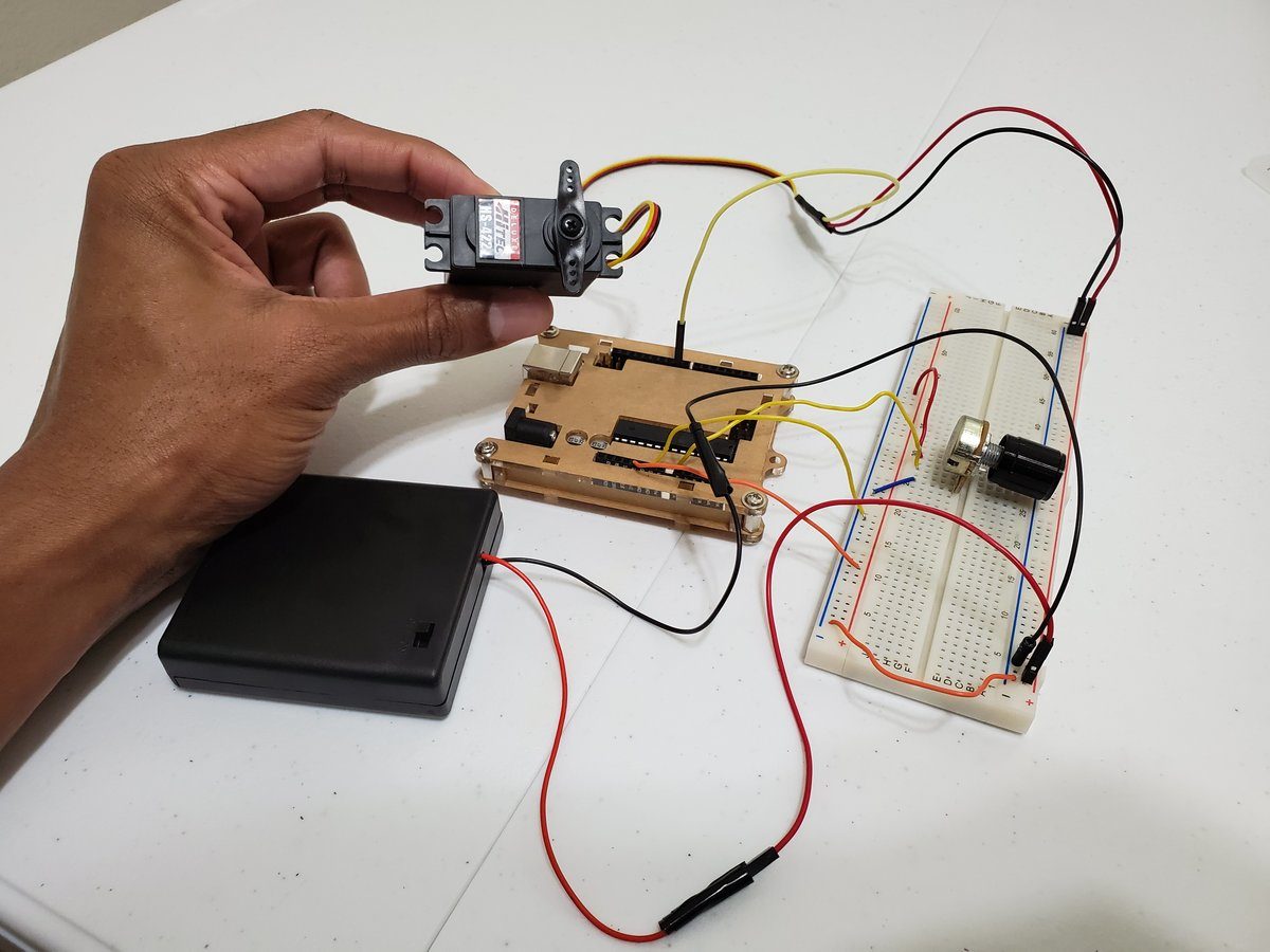
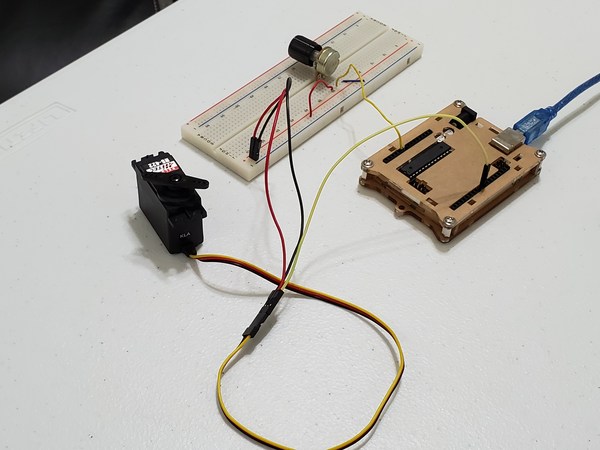
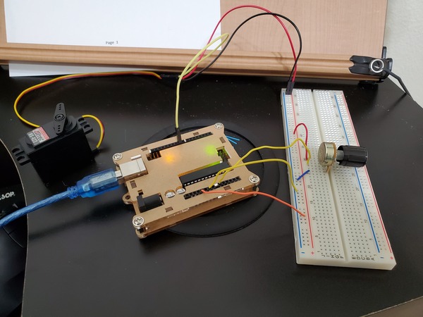
So let’s set all this up. Here is the schematic diagram:
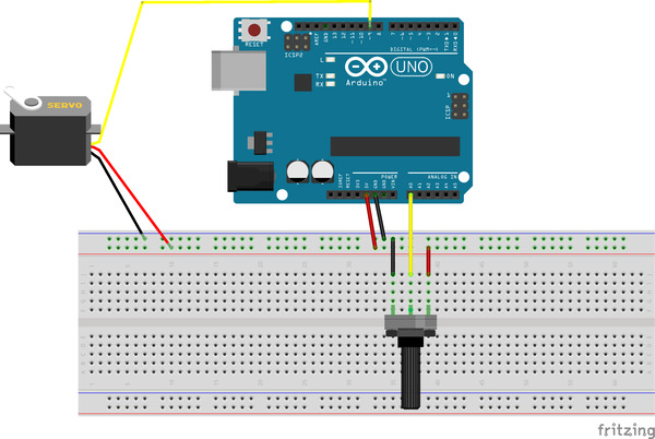
With your Arduino unplugged, stick the 10k Ohm potentiometer into the solderless breadboard. Make sure each terminal is connected to separate row in the breadboard.
Connect one of the outer terminals to the blue (ground) rail of the breadboard.
Connect the other outer terminal to the red (positive) rail of the breadboard.
Connect the central pin of the potentiometer to Analog Input pin A0 of the Arduino.
Connect the black and red wires of the servo to the blue and red rail of the breadboard, respectively.
Connect the yellow control wire to pin 9 of the Arduino.
Connect a wire from the +5V pin of the Arduino to the positive red rail of the breadboard.
Connect a wire from Ground (GND) of the Arduino to the blue rail of the breadboard.
This completes the hardware setup.
Plug in the Arduino.
Open up the IDE. Inside a new sketch, write the following code:
/*
 Controlling a servo position using a potentiometer (variable resistor)
 by Michal Rinott <http://people.interaction-ivrea.it/m.rinott>

 modified on 8 Nov 2013
 by Scott Fitzgerald
 http://www.arduino.cc/en/Tutorial/Knob
*/

#include <Servo.h>

Servo myservo;  // create servo object to control a servo

int potpin = 0;  // analog pin used to connect the potentiometer
int val;    // variable to read the value from the analog pin

void setup() {
  myservo.attach(9);  // attaches the servo on pin 9 to the servo object
}

void loop() {
  val = analogRead(potpin);            // reads the value of the potentiometer (value between 0 and 1023)
  val = map(val, 0, 1023, 0, 180);     // scale it to use it with the servo (value between 0 and 180)
  myservo.write(val);                  // sets the servo position according to the scaled value
  delay(15);                           // waits for the servo to get there
}
Upload the code to your board.
Turn the knob on your potentiometer to move the servo.
Your Arduino microcontroller is reading the voltage that is coming in from the potentiometer on Analog Input pin 0. It is then converting this voltage into a value between 0 and 180. This degree value then gets sent down the yellow control wire to the servo, and the servo moves accordingly. Thus, the higher the voltage output by the potentiometer, the greater the servo’s angle of rotation.
Control a Servo Using an External Power Supply
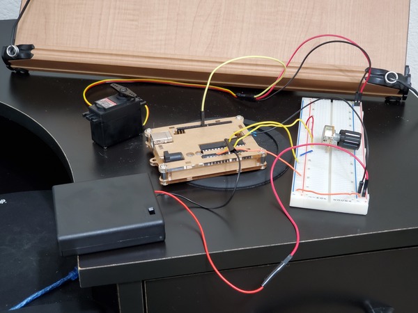
We don’t always want to use the Arduino to power our servos. Sometimes we might want to use an external power supply. Here is a basic schematic (Note: Ignore the AAA on the batteries below. They are actually AA.):
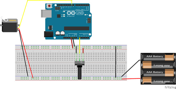
The biggest change from the previous implementation is that now the servos are connected to the 4xAA battery holder instead of the Arduino’s power supply.
With your Arduino powered off, move the red and black wires of the servo to the other red and blue rails of your solderless breadboard.
Connect the red wire of the 4xAA battery holder to the red rail of the solderless breadboard (the one electrically connected to the servo).
Connect the black wire of the 4xAA battery holder to the blue rail of the breadboard.
Make sure your external power supply is connected to the same ground as the Arduino. Use a male-to-male jumper wire to connect both ground rails. This is called common ground.
Power up the Arduino, open the IDE, and find the same sketch as the previous section of this blog post.
Upload the sketch to your Arduino.
Turn the knob of the potentiometer, and watch the servo move.