

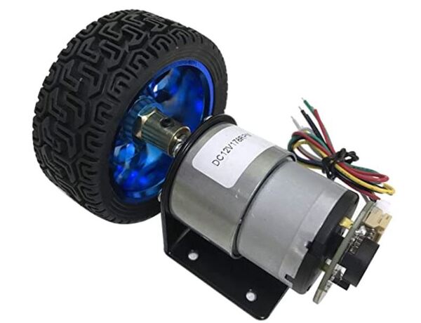
In this tutorial, we will learn how to calculate the number of pulses per 360 degree revolution for a DC motor with a built-in encoder. The motor that we will work with looks like the following image, however you can use any motor that looks similar to it:
Real-World Applications
When we know the number of pulses that an encoder outputs for each 360-degree turn of a motor, we can use that information to calculate the angular velocity of the wheels (in radians per second).
When we know the angular velocity of the wheels on a robot and the radius of the wheels, we can calculate how fast the robot is moving (i.e. speed) as well as the distance a robot has traveled in a given unit of time. This information is important for helping us determine where a robot is in a particular environment.
Prerequisites
- You have the Arduino IDE (Integrated Development Environment) installed on either your PC (Windows, MacOS, or Linux).
You Will Need
This section is the complete list of components you will need for this project (#ad).
- 2 x JGB37-520B DC Motor with Encoder OR 2 x JGB37-520B DC 6V 12V Micro Geared Motor With Encoder and Wheel Kit (includes wheels)
- Arduino Uno r3
OR
- Self-Balancing Car Kit (which includes everything above and more…Elegoo and Osoyoo are good brands you can find on Amazon.com)
Disclosure (#ad): As an Amazon Associate I earn from qualifying purchases.
What is a Pulse?
When a motor with a built-in encoder rotates, it generates pulses, which are alternating electrical signals of high voltage and low voltage. Each time the signal goes from low to high (i.e. rising), we count that as a single pulse.
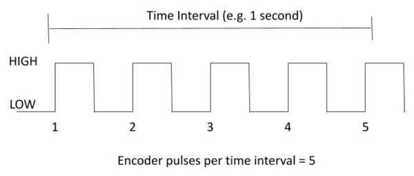
Our goal is to take our motor and measure the number of encoder pulses (often referred to as “ticks”) it generates in a single 360 degree turn of the motor.
Set Up the Hardware
The first thing we need to do is set up the hardware.
Here is the wiring diagram:
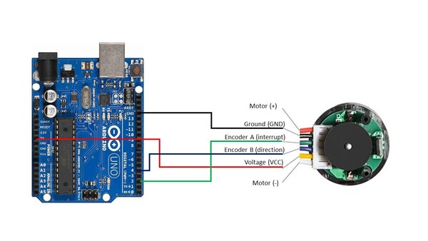
- The Ground pin of the motor connects to GND of the Arduino.
- Encoder A (sometimes labeled C1) of the motor connects to pin 2 of the Arduino. Pin 2 of the Arduino will record every time there is a rising digital signal from Encoder A.
- Encoder B (sometimes labeled C2) of the motor connects to pin 4 of the Arduino. The signal that is read off pin 4 on the Arduino will determine if the motor is moving forward or in reverse. We’re not going to use this pin in this tutorial, but we will use it in a future tutorial.
- The VCC pin of the motor connects to the 5V pin of the Arduino. This pin is responsible for providing power to the encoder.
- For this project, you don’t need to connect the motor pins (+ and – terminals) to anything since you will be turning the motor manually with your hand.
Write and Load the Code
Now we’re ready to calculate the number of encoder pulses per revolution. Open the Arduino IDE, and write the following program. The name of my program is pulses_per_revolution_counter.ino.
/*
 * Author: Automatic Addison
 * Website: https://automaticaddison.com
 * Description: Count the number of encoder pulses per revolution.
 */

// Encoder output to Arduino Interrupt pin. Tracks the pulse count.
#define ENC_IN_RIGHT_A 2

// Keep track of the number of right wheel pulses
volatile long right_wheel_pulse_count = 0;

void setup() {

  // Open the serial port at 9600 bps
  Serial.begin(9600);

  // Set pin states of the encoder
  pinMode(ENC_IN_RIGHT_A , INPUT_PULLUP);

  // Every time the pin goes high, this is a pulse
  attachInterrupt(digitalPinToInterrupt(ENC_IN_RIGHT_A), right_wheel_pulse, RISING);

}

void loop() {

    Serial.print(" Pulses: ");
    Serial.println(right_wheel_pulse_count);
}

// Increment the number of pulses by 1
void right_wheel_pulse() {
  right_wheel_pulse_count++;
}
Compile the code by clicking the green checkmark in the upper-left of the IDE window.
Connect the Arduino board to your personal computer using the USB cord.
Load the code we just wrote to your Arduino board.
Now, follow the following steps in the image below.
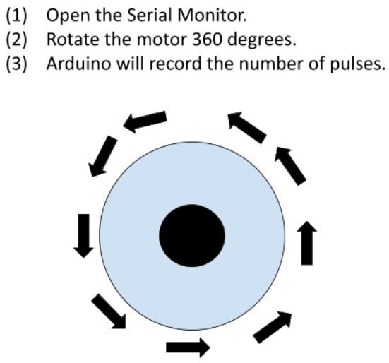
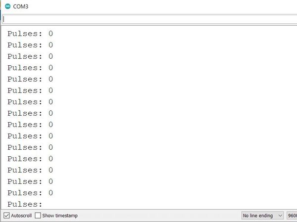
When you open the Serial Monitor, the pulse count should be 0.
Using your hand, rotate the motor a complete 360-degree turn.
Here is the output. We can see that there were 620 pulses generated.
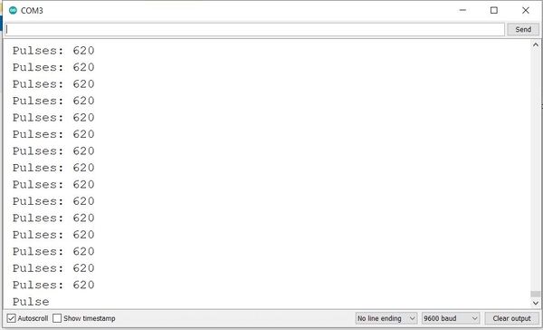
Thus, this motor generates 620 pulses per revolution.
That’s it. Keep building!