In this post, I’ll explain how to develop an Arduino-Based Optical Tachometer that measures the speed of a brushless propeller. The speed of the propeller must be measured using an IR Emitter/Detector pair using either Round Robin with Interrupts or Function Queue Scheduling. The
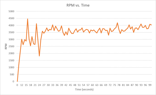
RPMs (revolutions per minute) must be captured over time, downloaded to a Host, and graphed.
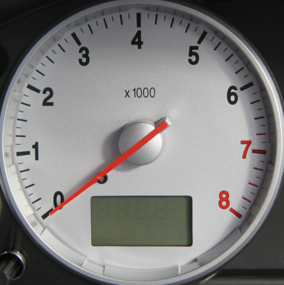
If you have ever driven a car or looked at the dashboard of a car, you have seen a tachometer. It is that meter on the other side of your speedometer that measures the rotation speed of your engine’s crankshaft in revolutions per minute (RPM). A tachometer is an instrument that measures the rotation speed of a shaft or disk, such as in a motor.
Requirements
Here are the requirements I created for this project:
- The system must execute on an Arduino.
- The speed of a brushless propeller must be measured using an Infrared (IR) Emitter/Detector pair
- The speed of a brushless propeller must be measured using Round Robin with Interrupts.
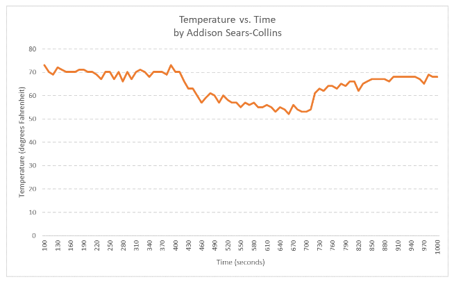
- The revolutions per minute (RPMs) must be captured over time.
- The RPMs must be downloaded to a Host.
- Time vs. RPMs must be graphed.
Hardware Design
The following components are used in this project. You will need:
- Arduino Uno Kit (Elegoo)
- Arduino Uno Board
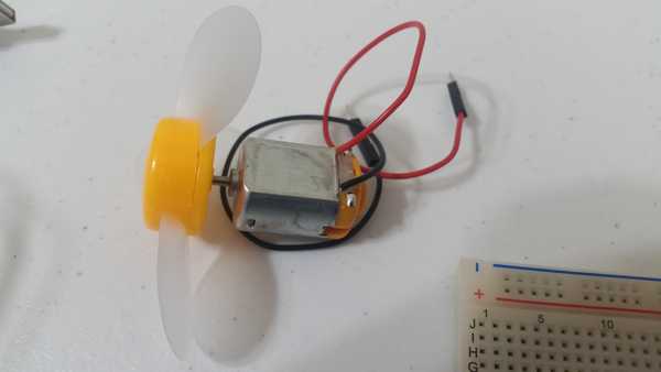
- Elegoo Motor 3-6V DC – For the propeller and motor system
- Propeller – For the propeller and motor system
- NPN Bipolar Transistor (PN2222) – For the propeller and motor system
- 1N4007 – General-Purpose Silicon Rectifier Diode (needed to dissipate current, protect the motor, in the event of a quick shut off of the transistor)
- 220Ω Resistor – For the propeller and motor system
- 330Ω Resistor – For the RPM measurement system
- 10kΩ Resistor – For the RPM measurement system
- Solderless Breadboard
- Male to Male Jumper Wire
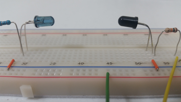
- Infrared Phototransistor (Receiver) and Infrared 5mm LED (Emitter; blue or clear in color)
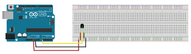
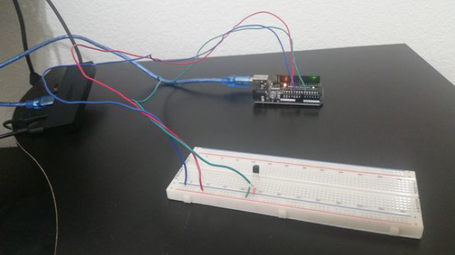
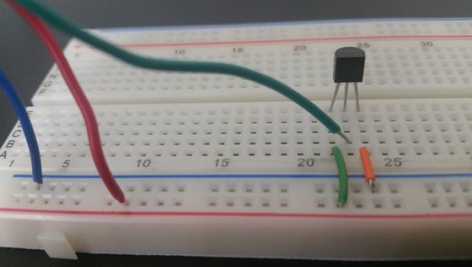
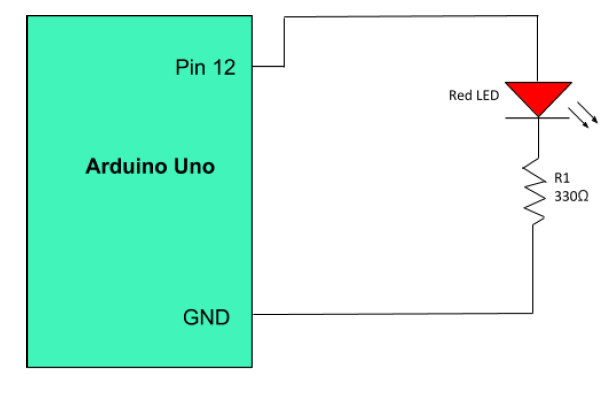
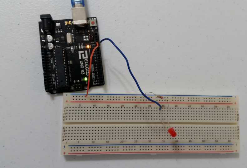
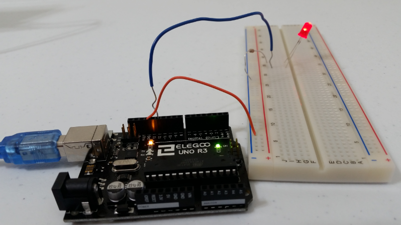
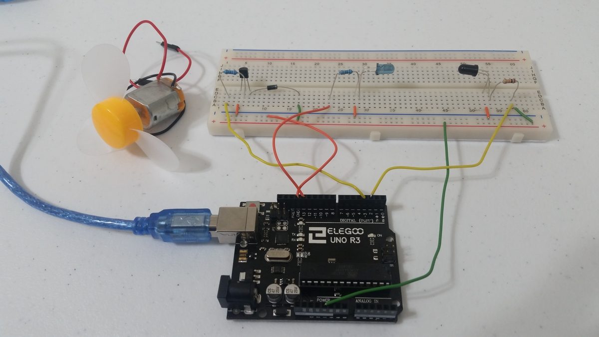
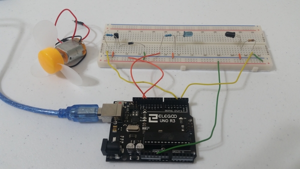
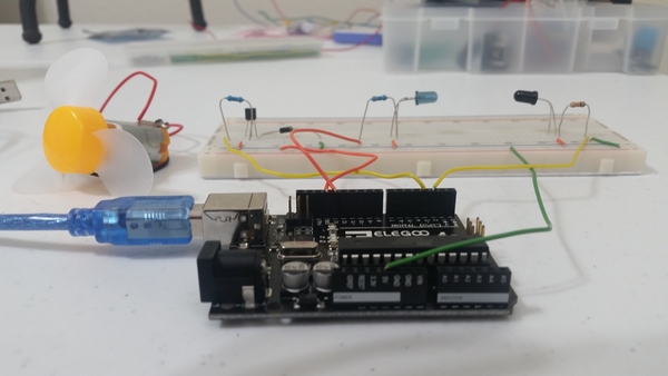
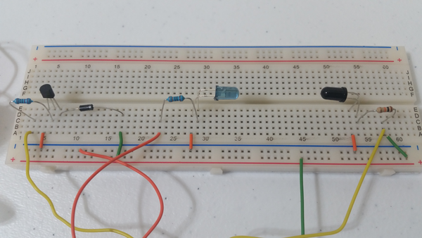
Here is the diagram of the hardware setup:
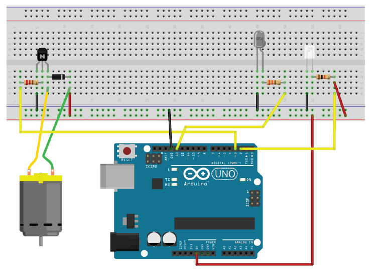
For the motor setup on the left of the image above, the current (when the transistor is “turned on”) goes from the 5V power supply, through the green wire, through the motor, and then down the yellow wire. It then passes through the collector towards the emitter, and then down to ground. If the transistor is shut off, it is no longer conducting. The residual peak current that would normally go through the transistor from the yellow wire needs somewhere to go. Instead of being forced through the non-conducting transistor (and potentially damaging it), the current redirects (shorts through the motor) and dissipates through the diode (from left to right through the diode in the schematic above) since diodes only allow current to travel in one direction.
Troubleshooting Tips
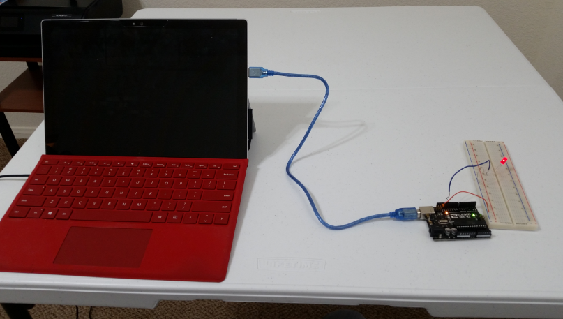
- There might be occasions where you start the motor (after you run the code in the Implementation section below), and the RPM readings start firing even though the propeller is nowhere near the IR emitter/receiver pair. If this happens to you, power the propeller/motor from a separate breadboard and Arduino.
- You will also need to take out the pieces of code from the code below that pertain to the operation of the motor and upload that code in a separate sketch to the other Arduino (the one that will power the propeller). It is a pain in the butt to do all this and can take several extra hours or so of development time, but it will help solve this problem.
- It is also helpful to cover the propeller blades with black electrical tape in case the IR emitter beam is passing right through the propeller blades.
Implementation
Here is the source code that you will need to load to your Arduino:
/**
 * In this program, we develop an Arduino-Based Optical Tachometer
 * that measures the speed of a brushless propeller.
 *
 * The Infrared LED is connected to pin 13.
 * The Infrared Phototransistor is connected to pin 2 (interrupts).
 *
 * @version 1.0 2019-02-18
 * @author Addison Sears-Collins
 */

// Assign a name to the DC motor pin on the Arduino Uno
const unsigned int MOTOR_PIN = 3;

// Assign a name to the infrared LED pin on the Arduino Uno
const unsigned int IR_LED = 13;

// The number of blades on the propeller. Adjust accordingly.
const unsigned int BLADE_COUNT = 3;

// Volatile keyword is used with interrupts
// This variable is subject to change inside an interrupt
// service routine
volatile unsigned int break_number = 0;

// Flag used to stop the program
bool done = false;

// Used for capturing the time
unsigned long time;

// Used for capturing the rpm (revolutions per minute)
unsigned int rpm;

/**
 *  Function runs only once, after each powerup or reset of the Arduino Uno
 */
void setup() {

  // Open the serial port and set the data transmission rate to 9600 bits
  // per second. 9600 is the default baud rate for Arduino Uno.
  Serial.begin(9600);

  // Show a welcome message as human-readable ASCII text
  Serial.println("PROPELLER RPM PROGRAM");
  Serial.println("This program transmits the time and RPM of a propeller.");
  Serial.println("Created by Addison Sears-Collins");
  Serial.println("");
  Serial.println("Press ! to end the program");
  Serial.println("");
  Serial.println("Please enter the desired speed of the motor.");
  Serial.println("Must be a value between 100 and 255.");
  Serial.println("");
  Serial.println("TIME, RPM");

  // The Infrared phototransistor is connected to pin 2.
  // Interrupt triggers when signal goes from HIGH to LOW
  attachInterrupt(digitalPinToInterrupt(2), isr_break_count, FALLING);

  // Turn on the IR Led
  pinMode(IR_LED, OUTPUT);
  digitalWrite(IR_LED, HIGH);

  // Enable output for the motor
  pinMode(MOTOR_PIN, OUTPUT);

  break_number = 0;
  rpm = 0;

}

/**
 *  Main function
 */
void loop() {

  display_time_and_rpm();

  start_motor();

  while(!done) {

    // Update time and rpm every second
    delay(1000);

    // Don't process interrupts during this calculation
    noInterrupts();

    // Calculate the RPM. If a 3-blade propeller, 3 breaks
    // per second would yield 1 rpm, which is 60 rpm.
    rpm = (60 * break_number) / BLADE_COUNT;

    // Display the time and rpm
    display_time_and_rpm();

    // End program if sentinel is entered
    end_program();

    break_number = 0;
    rpm = 0;

    // Restart interrupts
    interrupts();
  }

  // Do nothing
  while (true) {}
}

/**
  * This function starts the motor
  */
void start_motor() {

  // Wait for the user to enter the speed of the motor
  while (Serial.available() == 0){};

  // Activate the motor
  int speed = Serial.parseInt();
  if (speed >= 100 && speed <= 255) {
    analogWrite(MOTOR_PIN, speed);
  }
}

/**
  * Interrupt service routine.
  * This function counts the number of interrupts
  */
void isr_break_count() {

  break_number++;

}

/**
  * Function displays the time and rpm
  */
void display_time_and_rpm() {

  // Capture the time and covert to seconds
  time = millis() / 1000;

  // Display the time
  Serial.print(time);
  Serial.print(" , ");
  // Println so the next line begins on a new line
  // Display the rpm
  Serial.println(rpm);
}

/**
  * This function ends the program
  */
void end_program() {

  // Used for reading data from the serial monitor
  char ch;

  // Check to see if ! is available to be read
  if (Serial.available()) {

    // Read the character
    // Serial.read() returns the first (oldest) character in the buffer
    // and removes that byte of data from the buffer
    ch = Serial.read();

    // End the program if an exclamation point is entered in the
    // serial monitor
    if (ch == '!') {
      done = true;

      // Turn off the motor
      analogWrite(MOTOR_PIN, 0);

      // Turn off the IR LED
      digitalWrite(IR_LED, LOW);

      Serial.println("Finished recording RPM. Goodbye.");
    }
  }
}