In this post, I’ll show you how to stream live video using a Raspberry Pi. To make it more fun, I actually strapped the camera and Raspberry Pi to a quadcopter, captured video, and streamed that video via Wifi to my laptop computer. I’ll walk you through all the steps below.
Requirements
Here are the requirements:
- Using a USB Webcam connected to the Raspberry Pi, capture video, download via WiFi to my laptop computer (Windows 10) and display on my laptop computer.
Design
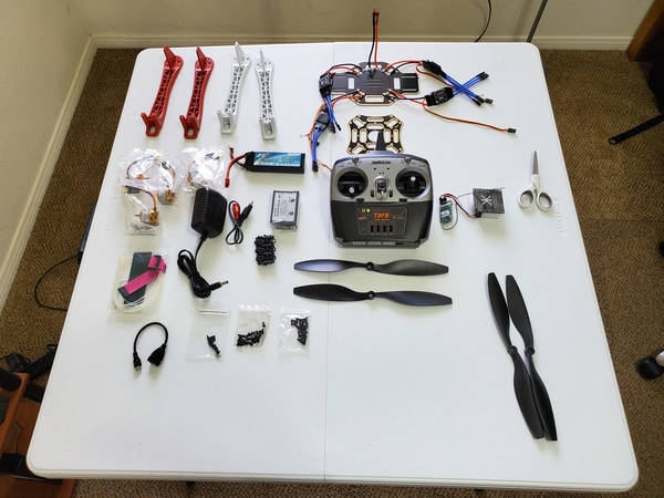
The following components are used in this project. You will need:
Here is the diagram of the hardware setup:
No diagram necessary.
Implementation
Hardware
First, I updated the packages. It is good practice to update all the Raspberry Pi software before installing new software. I went to the terminal inside Raspberry Pi, and I typed the following commands in order to make sure that I am using the latest version:
sudo apt-get update
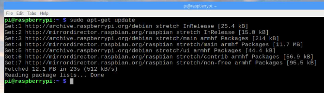
sudo apt-get upgrade
I waited several minutes for the upgrade to perform.
I then restarted the Raspberry Pi using the following command:
sudo reboot
Then, I typed the following command to start the installation:
sudo apt-get install motion
I typed in the following command and pressed Enter to see if the system is recognizing my USB web camera.
lsusb
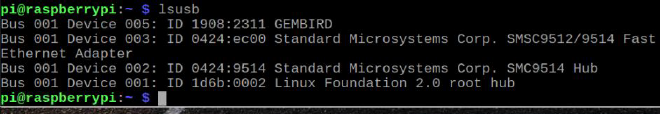
The name of the USB web camera is GEMBIRD as seen in the above screenshot.
I made edits to the configuration file, motion.conf, using the following command:
sudo nano /etc/motion/motion.conf
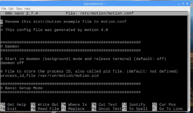
I made sure the settings were as follows:
- daemon on
- framerate 100
- stream_localhost off
- stream_port 8081
- stream_quality 100
- stream_maxrate 100
- width 640
- height 480
- webcontrol_localhost off
- quality 100
- post_capture 5
I pressed ctrl + x to exit.
I typed y to save.
I typed enter to confirm.
I typed the following command and pressed Enter:
sudo nano /etc/default/motion
I changed the following line:
start_motion_daemon=yes
I saved and exited by pressing ctrl+x then y
I restarted the service to make sure the web page would load:
sudo service motion restart
To start the service, I typed the following command:
sudo motion
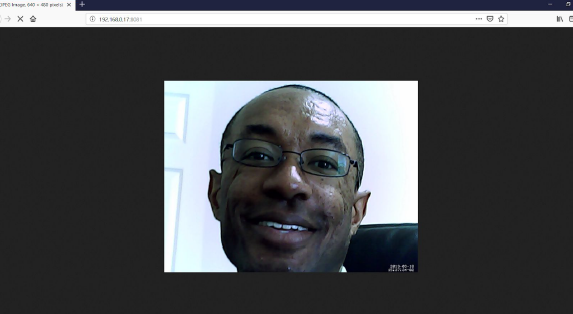
Next, I checked the webcam stream at the IP address of the Raspberry Pi:
192.168.0.17:8081
To stop the service, I ran the following line:
sudo service motion stop
To start the service again, I ran the following line:
sudo service motion start
I then typed the following command:
sudo motion
Next, I checked the webcam stream at the IP address of the Raspberry Pi:
192.168.0.17:8081
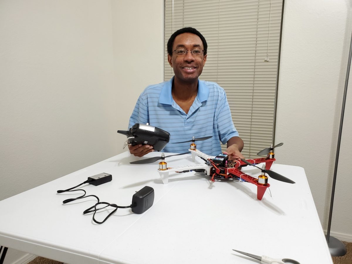
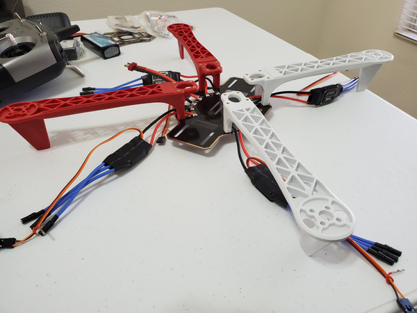
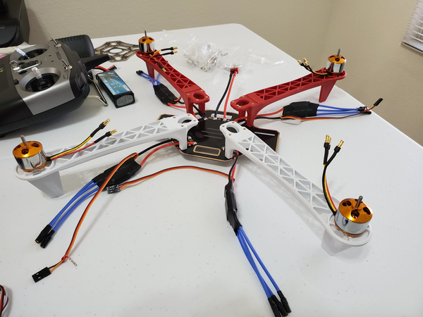
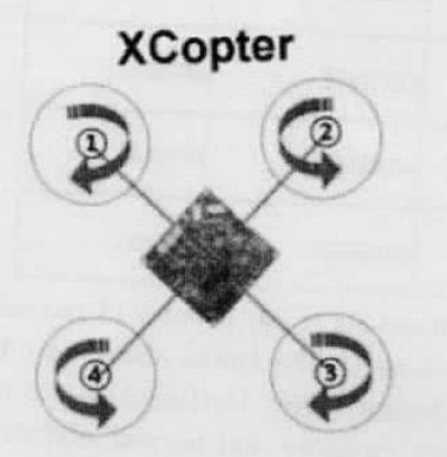
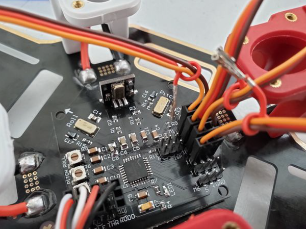
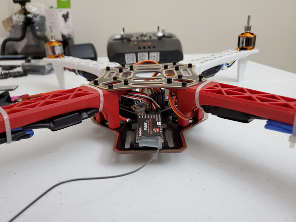
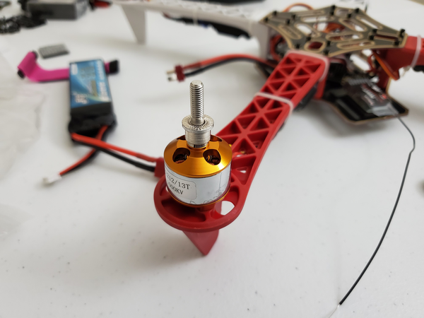
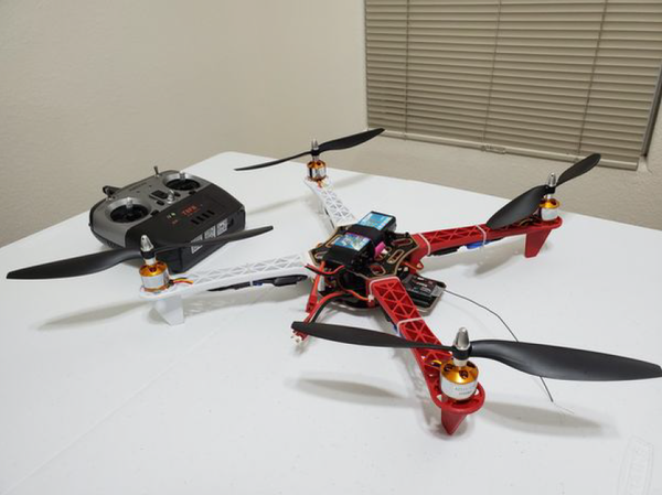
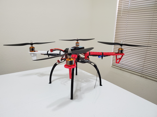
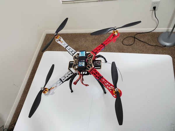
I then mounted the Raspberry Pi, battery, and webcam on the quadcopter.
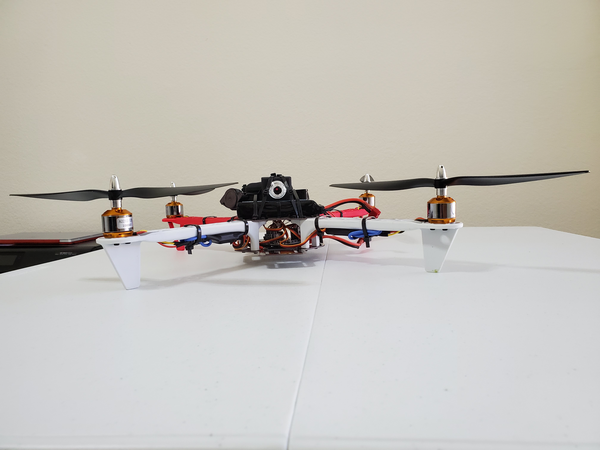
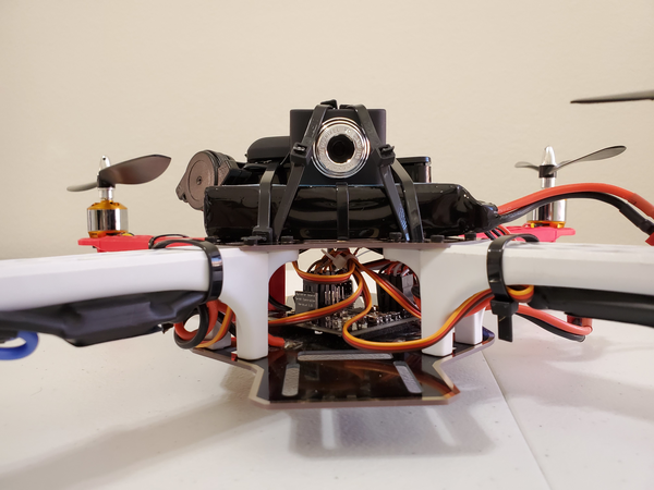
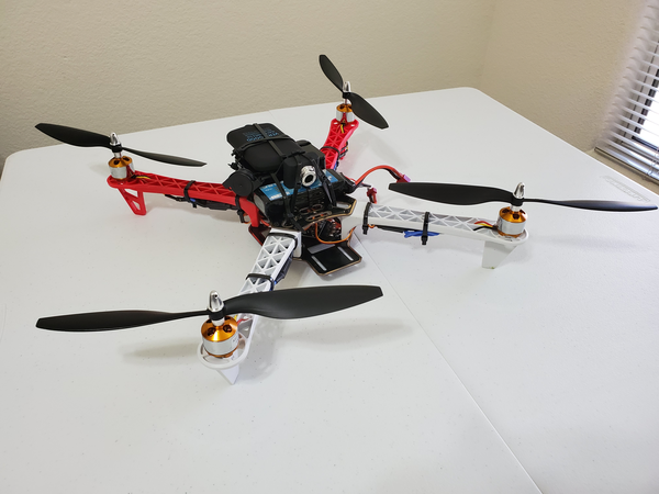
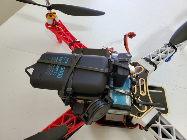
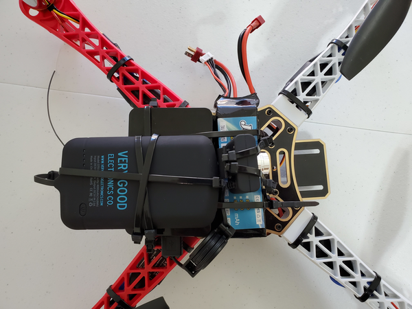
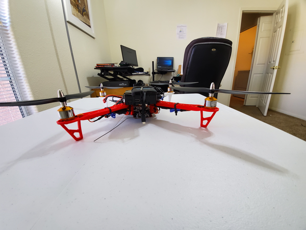
I then flew the quadcopter and streamed the video via WiFi to my host computer. See the video below in the next section.
Software
No software was necessary.