

Have you ever wondered how robots navigate their environments so precisely? A key component for many mobile robots is differential drive. This type of robot uses two independently controlled wheels, allowing for maneuvers like moving forward, backward, and turning.
But how does the robot itself know where it is and how far it’s traveled? This is where wheel odometry comes in.
Wheel odometry is a technique for estimating a robot’s position and orientation based on the rotations of its wheels. By measuring the number of revolutions each wheel makes, we can calculate the distance traveled and any changes in direction. This information is important for tasks like path planning, obstacle avoidance, and overall robot control.
This tutorial will guide you through calculating wheel odometry for a differential drive robot. We’ll explore how to convert raw wheel encoder data – the number of revolutions for each wheel – into the robot’s displacement in the x and y directions (relative to a starting point) and the change in its orientation angle. Buckle up and get ready to dive into the fascinating world of robot self-localization!
Prerequisites
- You understand how to turn robot linear and angular velocity commands into wheel velocities in revolutions per second.
Calculate Wheel Displacements
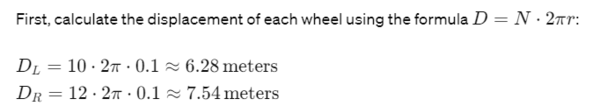
First, we calculate the distance each wheel has traveled based on the number of revolutions since the last time step. This requires knowing:
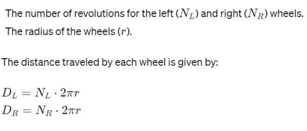
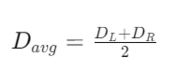
Calculate the Robot’s Average Displacement and Orientation Change
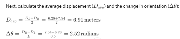
Next, we determine the robot’s average displacement and the change in its orientation. The average displacement (Davg) is the mean of the distances traveled by both wheels:
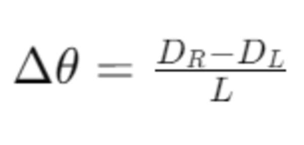
The change in orientation (Δθ), measured in radians, is influenced by the difference in wheel displacements and the distance between the wheels (L):
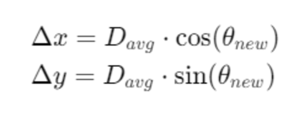
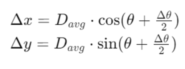
Calculate Changes in the Global Position
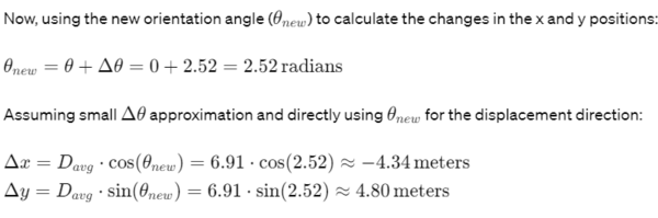
Now, we can calculate the robot’s movement in the global reference frame. Assuming the robot’s initial orientation is θ, and using Davg and Δθ, we find the changes in the x and y positions as follows:
You will often see the following equation instead:
This simplification assumes Δθ is relatively small, allowing us to approximate the displacement direction using the final orientation θnew without significant loss of accuracy. It’s a useful approximation for small time steps or when precise integration of orientation over displacement is not critical.
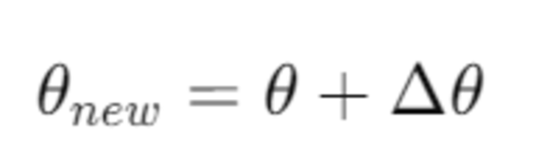
To find the robot’s new orientation:
Note, for robotics projects, it is common for us to modify this angle so that it is always between -pi and +pi. Here is what that code would look like:
# Keep angle between -PI and PI
if (self.new_yaw_angle > PI):
    self.new_yaw_angle = self.new_yaw_angle - (2 * PI)
if (self.new_yaw_angle < -PI):
    self.new_yaw_angle = self.new_yaw_angle + (2 * PI)
For ROS 2, you would then convert this new yaw angle into a quaternion.
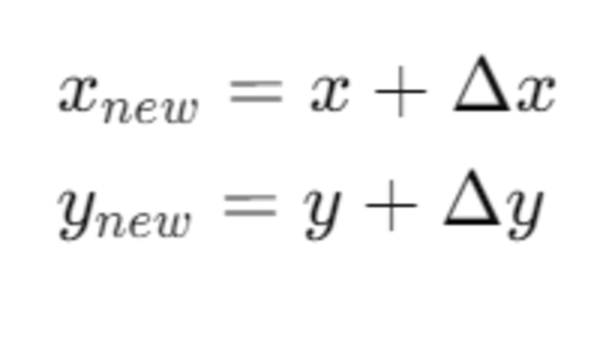
Update the Robot’s Global Position
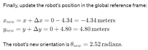
Finally, we update the robot’s position in the global reference frame. If the robot’s previous position was (x, y), the new position (xnew, ynew) is given by:
Practical Example
Let’s apply these steps with sample values:
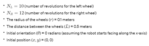
Using these values, we’ll calculate the robot’s new position and orientation.
Step 1: Wheel Displacements
Step 2: Average Displacement and Orientation Change
Step 3: Changes in Global Position
Step 4: New Global Position and Orientation
Therefore the new orientation of the robot is 2.52 radians, and the robot is currently located at (x=-4.34, y = 4.80).
Important Note on Assumptions
The calculations for wheel odometry as demonstrated in the example above are made under two crucial assumptions:
- No Wheel Slippage: It’s assumed that the wheels of the robot do not slip during movement. Wheel slippage can occur due to loss of traction, often caused by slick surfaces or rapid acceleration/deceleration. When slippage occurs, the actual distance traveled by the robot may differ from the calculated values, as the wheel rotations do not accurately reflect movement over the ground.
- Adequate Friction: The calculations also assume that there is adequate friction between the wheels and the surface on which the robot is moving. Adequate friction is necessary for the wheels to grip the surface effectively, allowing for precise control over the robot’s movement. Insufficient friction can lead to wheel slippage, which, as mentioned, would result in inaccuracies in the odometry data.
These assumptions are essential for the accuracy of wheel odometry calculations. In real-world scenarios, various factors such as floor material, wheel material, and robot speed can affect these conditions.
Therefore, while the mathematical model provides a foundational understanding of how to calculate a robot’s position and orientation based on wheel rotations, you should be aware of these limitations and consider implementing corrective measures or additional sensors to account for potential discrepancies in odometry data due to slippage or inadequate friction.