In this post, I’ll show you how to send roll, pitch, and yaw data over Bluetooth using Raspberry Pi and Arduino.
Requirements
Here are the requirements:
- Using the IMU connected to the Arduino, capture roll, pitch, and yaw data.
- Send the data via Serial over USB to the Raspberry Pi.
- Send the data via Bluetooth from Raspberry Pi to my host computer (e.g. my personal laptop).
- Display the data on my host computer.
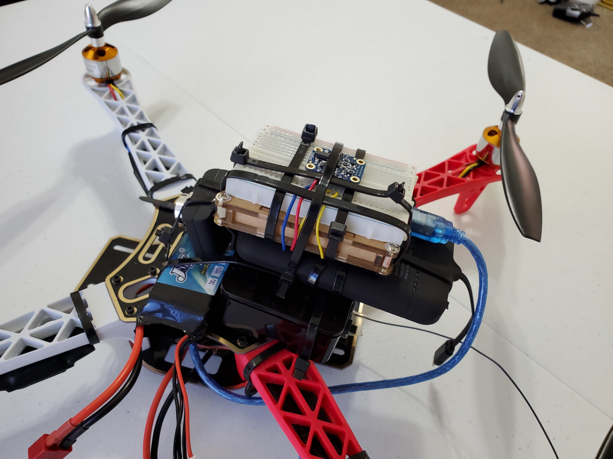
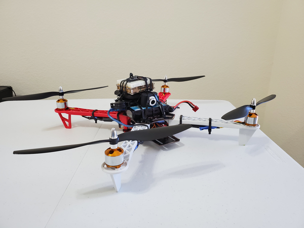
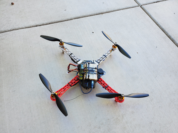
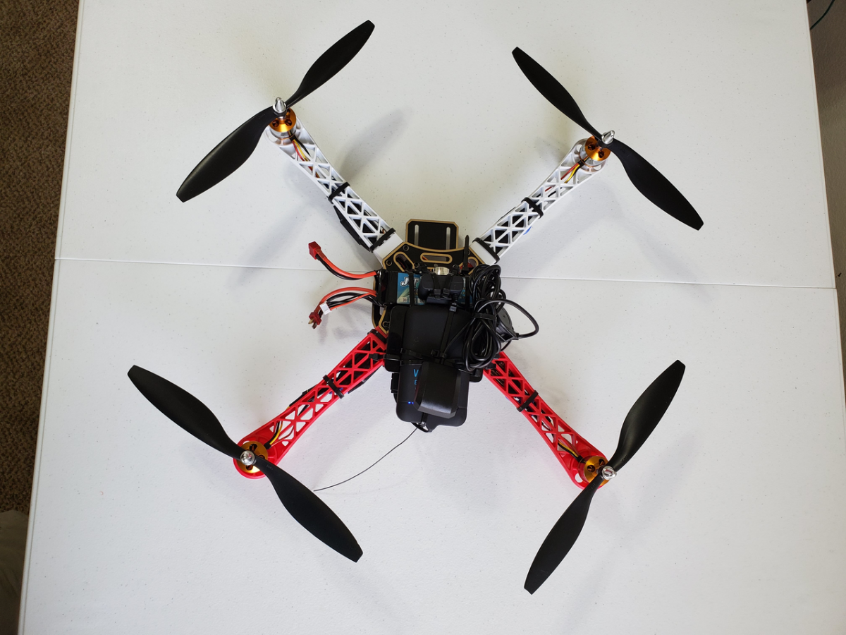
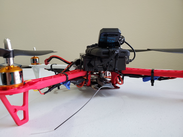
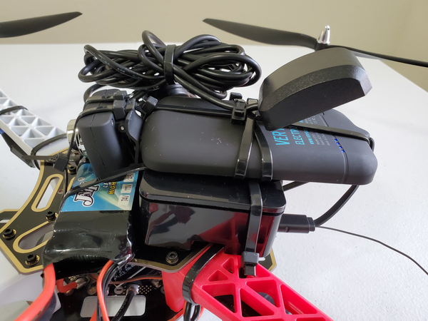
- To make things interesting, I mounted the IMU on a quadcopter.
Design
Hardware
The following components are used in this project. You will need:
- Raspberry Pi 3 (RPi3) Kit
- Arduino Uno
- Adafruit 9-DOF Absolute Orientation IMU Fusion Breakout – BNO055
- Solderless Breadboard
- Male to Male Jumper Wire
Software
Here are the steps for the software of the system:
- Set the delay between fresh samples.
- Establish a function to end the program when a sentinel is entered (in this case “!”).
- Define a method that displays some basic information on the sensor.
- Define a method that displays some basic information about the sensor status.
- Define a method that displays the sensor calibration status.
- Setup Function:
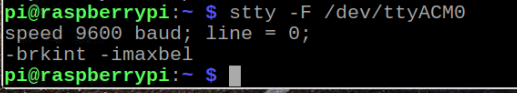
- Initialize serial communication at 9600 bits per second
- Initialize the sensor.
- Display some basic information on this sensor.
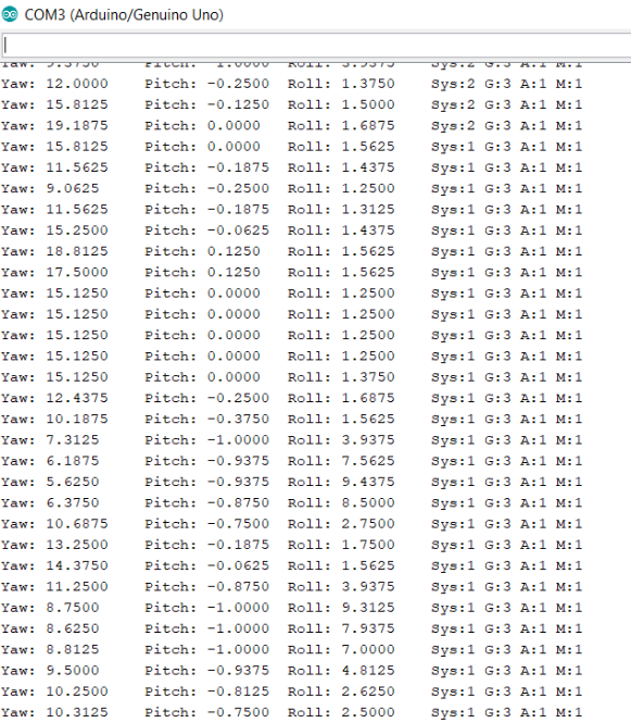
- Captures Roll+Pitch+Yaw data from the Adafruit BNO055.
- Print data to the Serial monitor.
- Go to new line.
- Wait a specified delay before requesting the next data.
- End the program when the sentinel is entered.
- Infinite loop.
Implementation
My Adafruit BNO055 Absolute Orientation Sensor was already setup from my Wifi roll, pitch, and yaw project. I made some modifications to the software though, which are presented in the Software section.
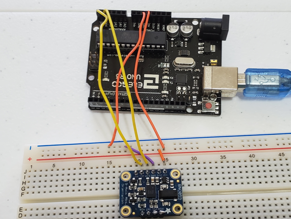
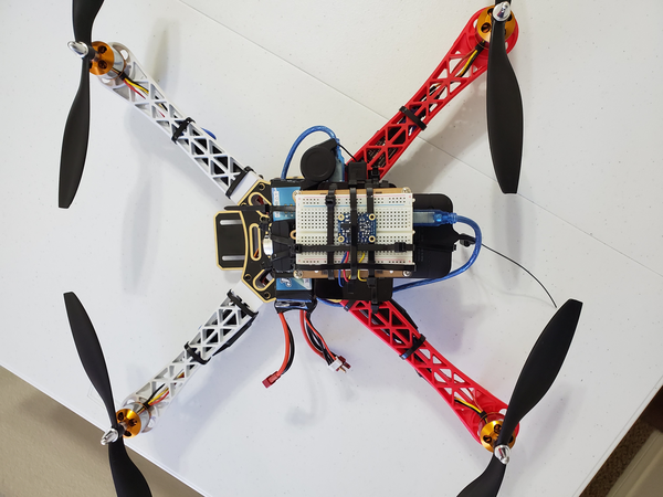
The BNO055 was wired to the Arduino Uno using the solderless breadboard as follows:
- Connected Vin to the power supply of 5V
- Connected GND to common power/data ground
- Connected the SDA pin to the I2C data SDA pin on the Arduino (A4).
- Connected the SCL pin to the I2C clock SCL pin on the Arduino (A5).
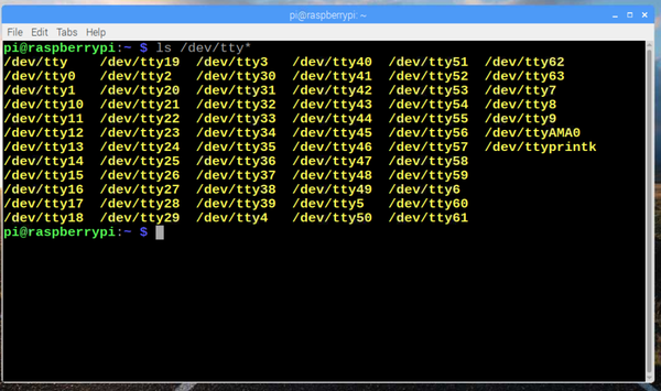
The challenge in this project is to set up Bluetooth on my Raspberry Pi and send the Roll+Pitch+Yaw data to my host computer.
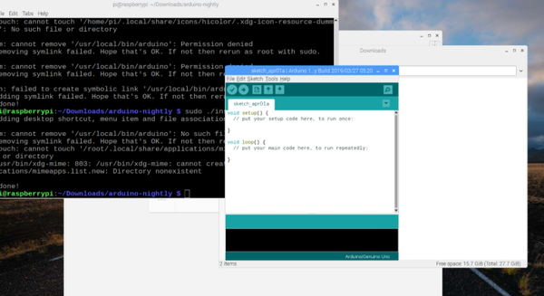
First, I installed the packages that will enable me to use Bluetooth on my Raspberry Pi.
I opened the Terminal and typed sudo apt-get install bluetooth bluez blueman. I pressed Enter.
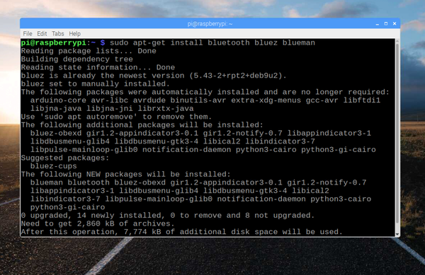
Here is a description of the packages:
- Blueman: A full featured Bluetooth manager. It provides a GUI-based setting panel Bluetooth manager.
- Bluez: Provides the Bluetooth protocol stack and the bluetoothctl utility.
- Bluetooth: Provides all the plugins supported by Bluez Bluetooth stack.
Once the packages were downloaded and installed, I typed:
sudo reboot
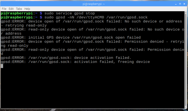
None of that worked, so I tried the steps here to configure the Bluetooth. Bluetooth was back!
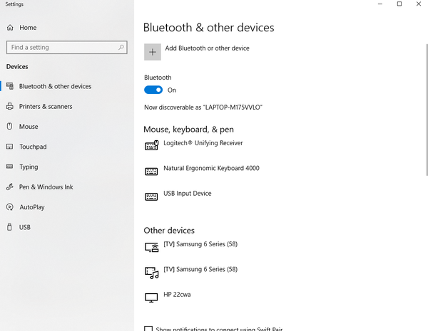
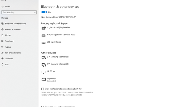
I made sure that I turned Bluetooth to on inside my Windows settings.
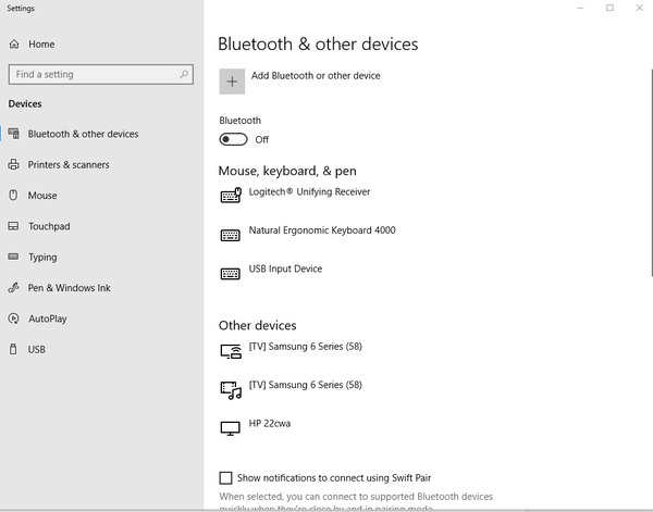
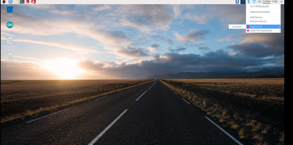
I paired with the Raspberry Pi. On the actual Raspberry Pi, I made sure to click “Make Discoverable” under the Bluetooth Manager settings.
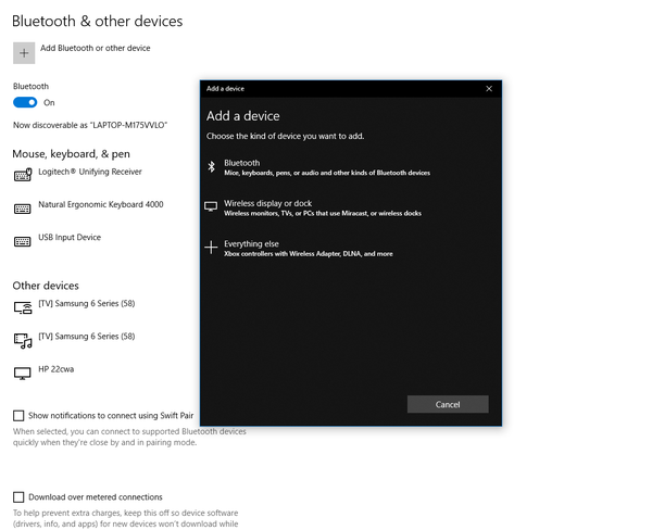
I went back to my Windows laptop and clicked “Bluetooth” under Add a device.
I added the Raspberry Pi.
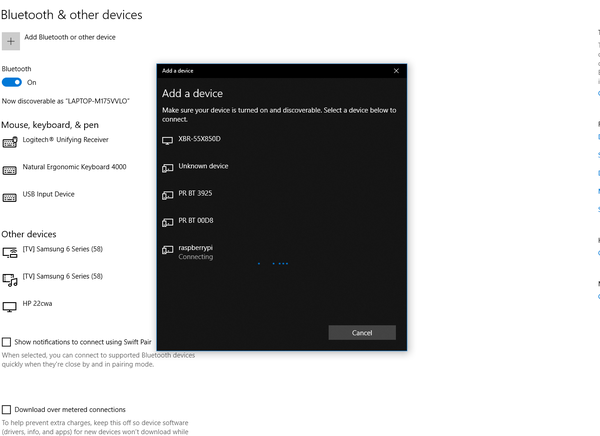
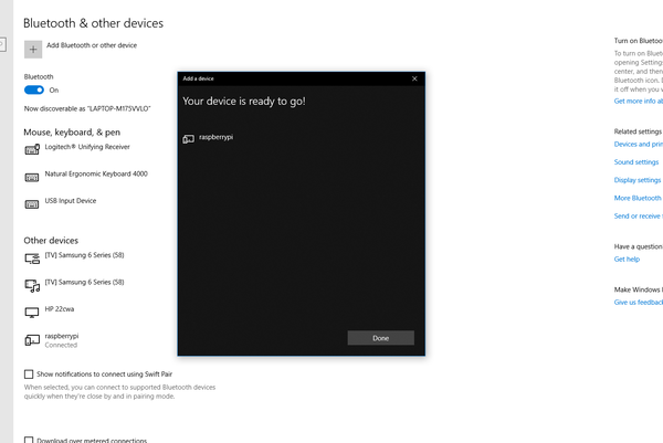
The Raspberry Pi and my Windows computer are now paired via Bluetooth.
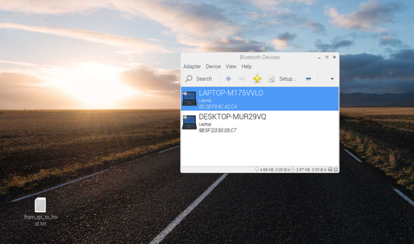
To access the Bluetooth graphical settings menu, on the Raspberry Pi desktop, I clicked Menu, located in the upper left corner of the screen, scrolled down to Preferences with the cursor and clicked Bluetooth Manager. From there I clicked “Send Files to Device” to send a test text file via Bluetooth from the Raspberry Pi to the Windows computer.
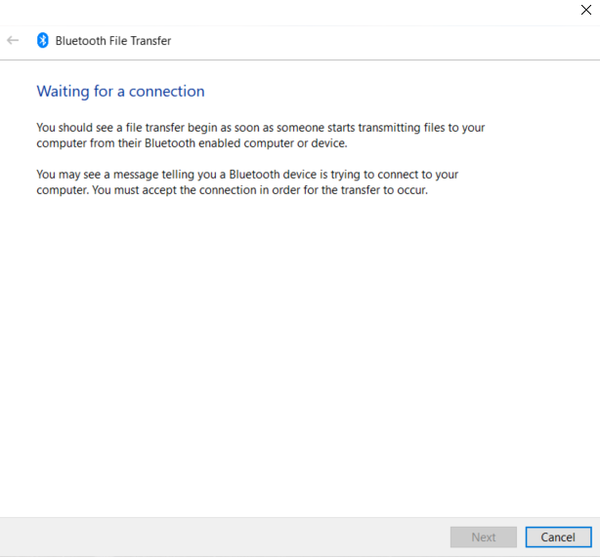
I went to the Bluetooth & other devices settings on my Windows computer and clicked on “Send or receive files via Bluetooth.” I clicked on “Receive files,” which opened up a window. The Windows computer is now ready to receive files.
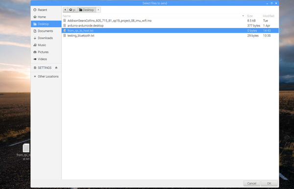
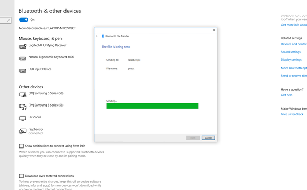
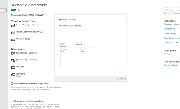
I then went back to the Raspberry Pi and selected the test text file and sent it to my Windows computer. I got a prompt on my Windows computer asking where it should be saved. Sending and receiving was successful!
Hardware
I used the same hardware as the Wifi-based roll, pitch, and yaw project.
Software
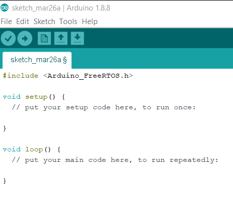
Here is the code for the program I developed. (Note that after you load the sketch to Arduino, the code runs automatically whenever the Arduino is connected to power. That could be via a battery or power directly from the Raspberry Pi):
#include <Wire.h>
#include <Adafruit_Sensor.h>
#include <Adafruit_BNO055.h>
#include <utility/imumaths.h>

/* This driver uses the Adafruit unified sensor library (Adafruit_Sensor),
   which provides a common 'type' for sensor data and some helper functions.

   To use this driver you will also need to download the Adafruit_Sensor
   library and include it in your libraries folder.

   You should also assign a unique ID to this sensor for use with
   the Adafruit Sensor API so that you can identify this particular
   sensor in any data logs, etc.  To assign a unique ID, simply
   provide an appropriate value in the constructor below (12345
   is used by default in this example).

   Connections
   ===========
   Connect SCL to analog 5
   Connect SDA to analog 4
   Connect VDD to 3-5V DC
   Connect GROUND to common ground

   History
   =======
   2015/MAR/03  - First release (KTOWN)
   2015/AUG/27  - Added calibration and system status helpers

   Modified by Addison Sears-Collins on May 3, 2019
*/

/* Set the delay between fresh samples */
#define BNO055_SAMPLERATE_DELAY_MS (100)

Adafruit_BNO055 bno = Adafruit_BNO055(55);

// Flag used to stop the program
bool done = false;

/**
 * This function ends the program.
 */
void end_program() {

  // Used for reading data from the serial monitor
  char ch;

  // Check to see if ! is available to be read
  if (Serial.available()) {

    // Read the character
    ch = Serial.read();

    // End the program if exclamation point is entered in the serial monitor
    if (ch == '!') {
      done = true;
      Serial.println("Finished recording Roll+Pitch+Yaw data. Goodbye.");
    }
  }
}

/**************************************************************************/
/*
    Displays some basic information on this sensor from the unified
    sensor API sensor_t type (see Adafruit_Sensor for more information)
*/
/**************************************************************************/
void displaySensorDetails(void)
{
  sensor_t sensor;
  bno.getSensor(&sensor);
  Serial.println("------------------------------------");
  Serial.print  ("Sensor:       "); Serial.println(sensor.name);
  Serial.print  ("Driver Ver:   "); Serial.println(sensor.version);
  Serial.print  ("Unique ID:    "); Serial.println(sensor.sensor_id);
  Serial.print  ("Max Value:    "); Serial.print(sensor.max_value); Serial.println(" xxx");
  Serial.print  ("Min Value:    "); Serial.print(sensor.min_value); Serial.println(" xxx");
  Serial.print  ("Resolution:   "); Serial.print(sensor.resolution); Serial.println(" xxx");
  Serial.println("------------------------------------");
  Serial.println("");
  delay(500);
}

/**************************************************************************/
/*
    Display some basic info about the sensor status
*/
/**************************************************************************/
void displaySensorStatus(void)
{
  /* Get the system status values (mostly for debugging purposes) */
  uint8_t system_status, self_test_results, system_error;
  system_status = self_test_results = system_error = 0;
  bno.getSystemStatus(&system_status, &self_test_results, &system_error);

  /* Display the results in the Serial Monitor */
  Serial.println("");
  Serial.print("System Status: 0x");
  Serial.println(system_status, HEX);
  Serial.print("Self Test:     0x");
  Serial.println(self_test_results, HEX);
  Serial.print("System Error:  0x");
  Serial.println(system_error, HEX);
  Serial.println("");
  delay(500);
}

/**************************************************************************/
/*
    Display sensor calibration status
*/
/**************************************************************************/
void displayCalStatus(void)
{
  /* Get the four calibration values (0..3) */
  /* Any sensor data reporting 0 should be ignored, */
  /* 3 means 'fully calibrated" */
  uint8_t system, gyro, accel, mag;
  system = gyro = accel = mag = 0;
  bno.getCalibration(&system, &gyro, &accel, &mag);

  /* The data should be ignored until the system calibration is > 0 */
  Serial.print("\t");
  if (!system)
  {
    Serial.print("! ");
  }

  /* Display the individual values */
  Serial.print("Sys:");
  Serial.print(system, DEC);
  Serial.print(" G:");
  Serial.print(gyro, DEC);
  Serial.print(" A:");
  Serial.print(accel, DEC);
  Serial.print(" M:");
  Serial.print(mag, DEC);
}

/**************************************************************************/
/*
    Arduino setup function (automatically called at startup)
*/
/**************************************************************************/
void setup(void)
{
  Serial.begin(9600);
  Serial.println("Orientation Sensor Test"); Serial.println("");

  /* Initialise the sensor */
  if(!bno.begin())
  {
    /* There was a problem detecting the BNO055 ... check your connections */
    Serial.print("Ooops, no BNO055 detected ... Check your wiring or I2C ADDR!");
    while(1);
  }

  delay(1000);

  /* Display some basic information on this sensor */
  displaySensorDetails();

  /* Optional: Display current status */
  displaySensorStatus();

  bno.setExtCrystalUse(true);
}

/**************************************************************************/
/*
    Arduino loop function, called once 'setup' is complete (your own code
    should go here)
*/
/**************************************************************************/
void loop(void)
{

  while (!done) {
    /* Get a new sensor event */
    sensors_event_t event;
    bno.getEvent(&event);

    /* Display the floating point data */
    Serial.print("Yaw: ");
    Serial.print(event.orientation.x, 4);
    Serial.print("\tPitch: ");
    Serial.print(event.orientation.y, 4);
    Serial.print("\tRoll: ");
    Serial.print(event.orientation.z, 4);

    /* Optional: Display calibration status */
    displayCalStatus();

    /* Optional: Display sensor status (debug only) */
    //displaySensorStatus();

    /* New line for the next sample */
    Serial.println("");

    /* Wait the specified delay before requesting next data */
    delay(BNO055_SAMPLERATE_DELAY_MS);

    end_program();

  }

  // Do nothing
  while (true){};
}