
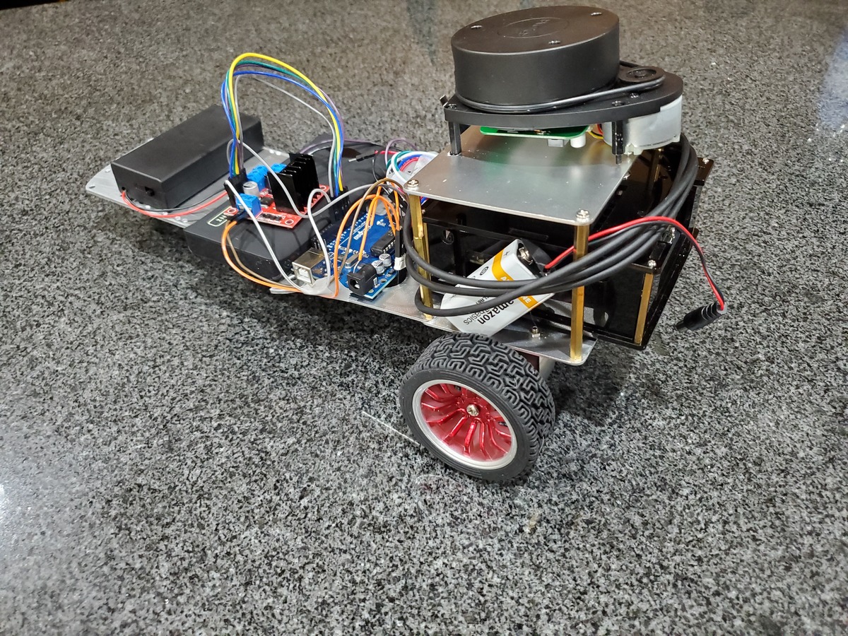
In this tutorial, we learn how to connect DC motors to Arduino and the L298N motor driver.
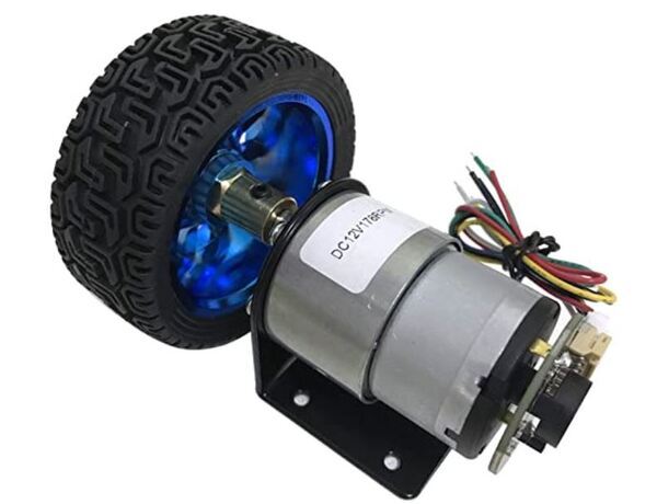
Here is the motor we will work with, but you can use any motor that looks like this one.
Prerequisites
You have the Arduino IDE (Integrated Development Environment) installed on your PC (Windows, MacOS, or Linux).
You Will Need
This section is the complete list of components you will need for this project (#ad).
- 2 x JGB37-520B DC Motor with Encoder OR 2 x JGB37-520B DC 6V 12V Micro Geared Motor With Encoder and Wheel Kit (includes wheels)
- Arduino Uno r3
OR
- Self-Balancing Car Kit (which includes everything above and more…Elegoo and Osoyoo are good brands you can find on Amazon.com)
I also bought the following:
- 9V Battery
- 9V DC Battery Power Cable Plug Clip Barrel Jack Connector
- 18650 Battery Holder 2 Slots
- Two 18650 3.7V Rechargeable Battery 2000mAh Li-ion
- L298N Motor Driver
- Assorted Breadboard Jumper Wires
Disclosure (#ad): As an Amazon Associate I earn from qualifying purchases.
Set Up the Hardware
The first thing we need to do is set up the hardware. Below is the wiring diagram, and here is the pdf version so you can see the pin numbers better:
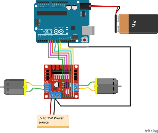
On my motors, the outer pins are the ones that drive the motors. These pins need to be connected to the L298N OUT1-OUT4 pins.
Remove the two black jumpers that are on the board that cover the ENA and ENB pins. Do not remove the other jumper that is near the power input pins.
Write the Code
Now let’s write the code. You will need to:
- Load this code to your Arduino from your PC.
- Remove the Arduino from your PC.
- Turn on your Arduino using the 9V battery.
/*
 * Author: Automatic Addison
 * Website: https://automaticaddison.com
 * Description: Controls the speed and direction of two DC motors.
 */

// Motor A connections
const int enA = 9;
const int in1 = 5;
const int in2 = 6;

// Motor B connections
const int enB = 10;
const int in3 = 7;
const int in4 = 8;

// Set the speed (0 = off and 255 = max speed)
const int motorSpeed = 128;

void setup() {

  // Motor control pins are outputs
  pinMode(enA, OUTPUT);
  pinMode(enB, OUTPUT);
  pinMode(in1, OUTPUT);
  pinMode(in2, OUTPUT);
  pinMode(in3, OUTPUT);
  pinMode(in4, OUTPUT);

  // Turn off motors - Initial state
  digitalWrite(in1, LOW);
  digitalWrite(in2, LOW);
  digitalWrite(in3, LOW);
  digitalWrite(in4, LOW);

  // Set the motor speed
  analogWrite(enA, motorSpeed);
  analogWrite(enB, motorSpeed);
}

void loop() {

  // Go forwards
  go_forward();
  delay(3000);

  // Go backwards
  go_backwards();
  delay(3000);

  // Go right
  go_right();
  delay(3000);

  // Go left
  go_left();
  delay(3000);

  // Stop
  stop_all();
  delay(3000);
}

/*
 *  Forwards, backwards, right, left, stop.
 */
void go_forward() {
  digitalWrite(in1, HIGH);
  digitalWrite(in2, LOW);
  digitalWrite(in3, HIGH);
  digitalWrite(in4, LOW);
}
void go_backwards() {
  digitalWrite(in1, LOW);
  digitalWrite(in2, HIGH);
  digitalWrite(in3, LOW);
  digitalWrite(in4, HIGH);
}
void go_right() {
  digitalWrite(in1, HIGH);
  digitalWrite(in2, LOW);
  digitalWrite(in3, LOW);
  digitalWrite(in4, HIGH);
}
void go_left() {
  digitalWrite(in1, LOW);
  digitalWrite(in2, HIGH);
  digitalWrite(in3, HIGH);
  digitalWrite(in4, LOW);
}
void stop_all() {
  digitalWrite(in1, LOW);
  digitalWrite(in2, LOW);
  digitalWrite(in3, LOW);
  digitalWrite(in4, LOW);
}
Run the Code
When you run this code, you will see your motors move forwards, backwards, right turn, left turn, and then stop. If your motors don’t do this exact sequence, consider switching the position of the wire connections that both motors have to the L298N.