
In this post, I’ll show you how to build a robot that is able to move autonomously through an obstacle course (i.e. multi-obstacle environment).

Table of Contents
- Requirements
- Prerequisites
- You Will Need
- Directions
- –Assemble the Body
- –Assemble the Brain
- –Assemble the Nervous System
- –Set Up Your Obstacle Course
- Upload the Final Code
- Deploy Your Robot
- Video
- Troubleshooting
Requirements
Here are our requirements (in order from when the robot starts moving, to when the robot stops moving):
- Robot shall start behind the starting line.
- Robot shall move forward once the program begins.
- Robot shall detect when it crosses over the starting line.
- Robot shall store the heading (direction) it is traveling at the moment it crosses the starting line.
- Robot shall start detecting obstacles as soon as it crosses the starting line.
- When not avoiding obstacles, the robot shall travel in the direction of the heading.
- Robot shall not touch any of the obstacles inside the obstacle course.
- Robot shall detect all obstacles that are at least 3 inches in height.
- Robot shall detect when it crosses the finish line.
- Robot shall travel in the direction of the heading for at least two seconds after it crosses the finish line.
- Robot shall come to a complete stop.
Prerequisites
- You have the Arduino IDE (Integrated Development Environment) installed on either your PC (Windows, MacOS, or Linux).
- If you have experience building a basic wheeled robot using Arduino, you will find this tutorial easier to follow. If you don’t have that experience, don’t worry. I’ll explain everything as we go.
You Will Need
The following components are used in this project. You will need:
- Robot “Body”
- Everything under the Body section of this tutorial (Buy Two of the 2WD Smart Robot Car Chassis Kits)
- 9V Battery Connector
- Robot “Brain”
- Robot’s “Nervous System”
- Soldering Equipment
- Check out this post for all the soldering equipment you will need
- Other Sensors
- Obstacle Course
- Silver Reflective Tape (I used 3M Scotchlite Silver Reflective Tape)
- 12-pack of Soda Cans (I’m using 12 Fl Oz Cans)
- Scotch Tape
Directions
Assemble the Body
The first thing we need to do is to assemble the body of the robot.
Open one of your robot car chassis kits.
Follow this video below to assemble the robot’s frame:
Check out this post for the complete instructions for assembling the robot body (assemble just the body, not the electronics, for now).
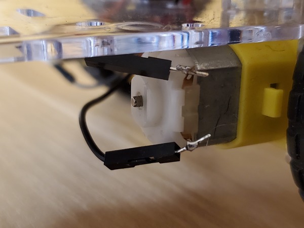
Make sure that you have some male-to-male wires soldered to each of the leads of the two robot motors.
Now, open the other robot car chassis kit.
Get one of the long robot car base pieces.
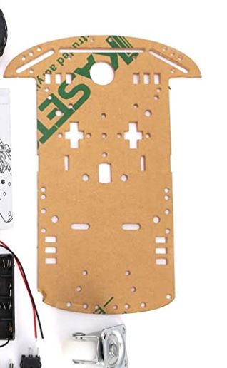
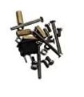
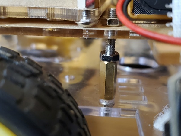
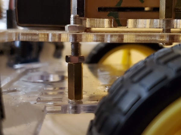
Also grab 2 standoffs, 2 long screws, and 4 hex nuts.
Use these standoffs, screws, and nuts to mount the base piece directly above the other base piece.
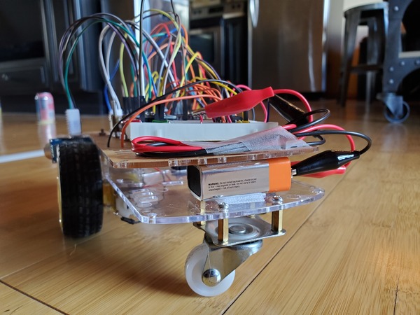
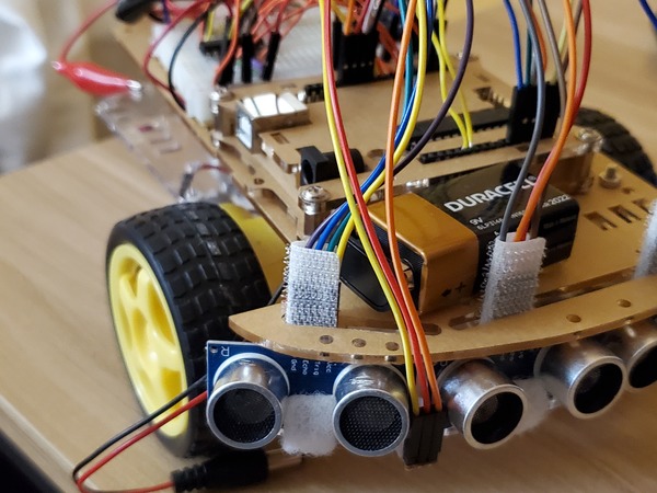
Grab a 7/8 inch Velcro Fastener Square and attach a single 9V battery on the other end of the robot.
Take another 9V battery and mount it on the front of the robot on top of the upper base piece.
Attach the 9V battery connector to the battery.
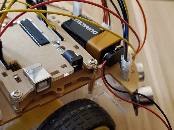
Assemble the Brain
Grab the Arduino and attach it just behind the 9V battery on the front of the robot (Ignore all those wires in the photo for now. You’ll get to those in a bit).
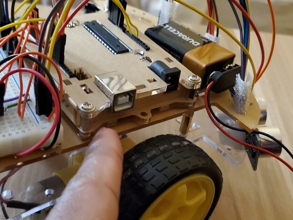
You can use the Velcro squares to make sure the Arduino stays put. Make sure the black power input on the Arduino can easily be reached by the 9V battery connector (don’t plug anything in yet).
Attach the 400-point solderless breadboard just behind the Arduino using some Velcro squares.
Assemble the Nervous System
Now that the robot has its brain (Arduino mounted on the back of the robot) and a body, it needs a “nervous system,” communication lines that enable the brain to transmit signals to and from different parts of its body. In the context of this project, those communication lines are the wires that we need to connect between the different parts of the robot we’re building.
Design the Circuit Diagram
Before we connect any wires or components, it is good practice to design the circuit diagram. For all my Arduino projects, I use a software called Fritzing, but you can even plan out your circuits by hand.
Here is the pdf of the complete circuit diagram. With this complete circuit diagram, you should connect component by component, following the wiring exactly as you see it in the pdf.
No need to hurry. Go slow so that you don’t make any mistakes.
Connect the L293D to the Solderless Breadboard
The first thing we need to do is connect the L293D motor controller.
Check out this section on “nervous system” to learn how.
Test Your Motor Connection
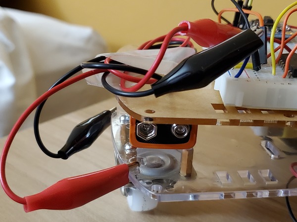
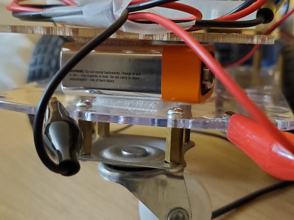
To test your motor connection, you will need to connect the 9V battery (the one at the back of the robot sandwiched between the upper and lower base pieces) to the 400-point solderless breadboard as shown in the circuit diagram.
I used alligator clips and some small pieces of male-to-male wire to connect the + and – terminals of the 9V battery to the red (positive) and blue (ground) rails of the solderless breadboard.
Here is the code to test the motors. Upload it to your Arduino from your computer.
/**
* Addison Sears-Collins
* March 21, 2020
* This code is used to test the DC motors
* with the Dual H-Bridge Motor Driver (L293D)
**/

/*---------------------------Definitions-------------------------------------*/
//Define pins for Motor A
#define ENABLE_A 5
#define MOTOR_A1 6
#define MOTOR_A2 4

// Define pins for Motor B
#define ENABLE_B 8
#define MOTOR_B1 7
#define MOTOR_B2 9

/*---------------------------Helper-Function Prototypes----------------------*/
void disableMotors(void);
void enableMotors(void);
void goForward(void);
void goLeft(void);
void goRight(void);
void setupPins(void);

/*---------------------------Module Code-------------------------------------*/
void setup() {

  setupPins();

  // Set the data rate in bits per second
  Serial.begin(9600);
}

void loop() {
  enableMotors();
  goForward();
  delay(2000);
  goRight();
  delay(500);
  goForward();
  delay(2000);
  goLeft();
  delay(500);
  goForward();
  delay(2000);
  disableMotors();
  delay(3000);
}

void disableMotors(){
  digitalWrite(ENABLE_A, LOW);
  digitalWrite(ENABLE_B, LOW);
}

void enableMotors(){
  digitalWrite(ENABLE_A, HIGH);
  digitalWrite(ENABLE_B, HIGH);
}

void goForward(){
  digitalWrite(MOTOR_A1, LOW);
  digitalWrite(MOTOR_A2, HIGH);
  digitalWrite(MOTOR_B1, LOW);
  digitalWrite (MOTOR_B2, HIGH);
}

void goLeft(){
  digitalWrite(MOTOR_A1, LOW);
  digitalWrite(MOTOR_A2, HIGH);
  digitalWrite(MOTOR_B1, HIGH);
  digitalWrite (MOTOR_B2, LOW);
}

void goRight(){
  digitalWrite(MOTOR_A1, HIGH);
  digitalWrite(MOTOR_A2, LOW);
  digitalWrite(MOTOR_B1, LOW);
  digitalWrite (MOTOR_B2, HIGH);
}

void setupPins(){
  // Configure motor pins
  pinMode(ENABLE_A, OUTPUT);
  pinMode(MOTOR_A1, OUTPUT);
  pinMode(MOTOR_A2, OUTPUT);
  pinMode(ENABLE_B, OUTPUT);
  pinMode(MOTOR_B1, OUTPUT);
  pinMode(MOTOR_B2, OUTPUT);
}
Place the robot on the ground, somewhere with a lot of space, and power up the Arduino board using the 9V battery. If the robot starts moving, everything is working properly.
Connect the BNO055 9-DOF Absolute Orientation IMU Fusion Breakout
The BNO055 has some pins that come with it. These pins need to be soldered to the BNO055. To see how to set up the BNO055 and make sure it is working, check out this video.
Sink the pins of the BNO055 down into the 400-point solderless breadboard so that it is at the other end of the L293D motor controller.
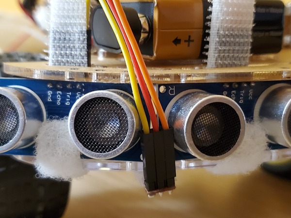
Connect the HC-SR04 Ultrasonic Sensors (the “Eyes”)
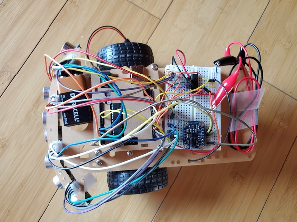
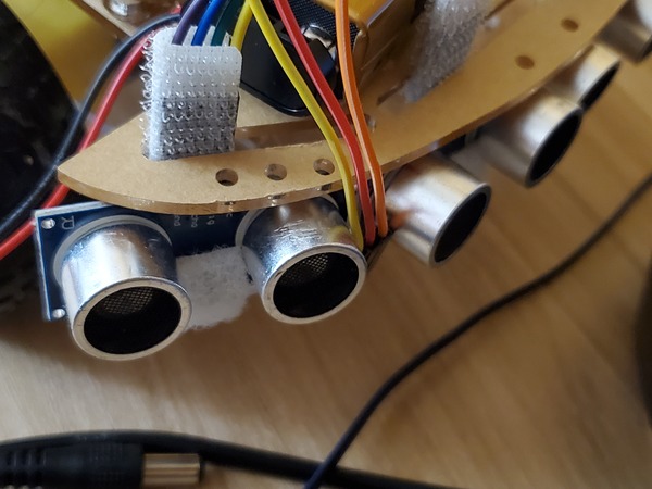
Attach the four HC-SR04 ultrasonic sensors to the front of the robot. These sensors are the “eyes” of the robot and are used to detect obstacles.
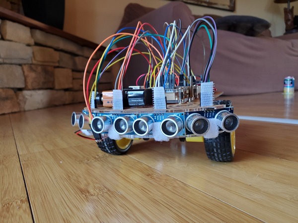
The pins of the sensors should slip right through the groove of the upper base piece.
Notice how I used some of the Velcro squares to keep the sensors in place and upright.
Wire the sensors exactly as shown in the circuit diagram. Take your time wiring everything up. There are a lot of wires, and you want to make sure everything is wired up correctly.
I used some Velcro squares at the point where the wires slip over the pins of the ultrasonic sensors so that everything stays firm in place.
Test Your HC-SR04 Ultrasonic Sensors
Upload this code to your Arduino:
/**
 *  This program tests the ultrasonic
 *  distance sensor (HC-SR04)
 *
 * @author Addison Sears-Collins
 * @version 1.0 2020-03-22
 */

/*---------------------------Definitions-------------------------------------*/

// Right sensor
#define TRIG_RIGHT A2
#define ECHO_RIGHT A1

// Right-center sensor
#define TRIG_RIGHT_CTR 12
#define ECHO_RIGHT_CTR 13

// Left-center sensor
#define TRIG_LEFT_CTR 10
#define ECHO_LEFT_CTR 11

// Left sensor
#define TRIG_LEFT 3
#define ECHO_LEFT 2

/*---------------------------Helper-Function Prototypes----------------------*/
void doPingRight(void);
void doPingRightCtr(void);
void doPingLeftCtr(void);
void doPingLeft(void);
void getDistances(void);
void setupPins(void);

/*---------------------------Module Variables----------------------*/
int distance_right;
int distance_rightctr;
int distance_leftctr;
int distance_left;

/*---------------------------Module Code-------------------------------------*/
void setup(){

  setupPins();

  // Setup serial communication
  Serial.begin(9600);
}

void loop(){

  getDistances();

  // Print the distances in inches
  Serial.println((String)"Distance Right: " + distance_right);
  Serial.println((String)"Distance Right Center: " + distance_rightctr);
  Serial.println((String)"Distance Left Center: " + distance_leftctr);
  Serial.println((String)"Distance Left: " + distance_left);
  Serial.println("");

  // Pause for 1.0 second
  delay(1000);
}

void doPingRight() {
  /*
   * Returns the distance to the obstacle as an integer in inches
   */
  // Make the Trigger LOW (0 volts) for 2 microseconds
  digitalWrite(TRIG_RIGHT, LOW);
  delayMicroseconds(2);

  // Emit high frequency 40kHz sound pulse
  // (i.e. pull the Trigger)
  // by making Trigger HIGH (5 volts)
  // for 10 microseconds
  digitalWrite(TRIG_RIGHT, HIGH);
  delayMicroseconds(10);
  digitalWrite(TRIG_RIGHT, LOW);

  // Detect a pulse on the Echo pin.
  // pulseIn() measures the time in
  // microseconds until the sound pulse
  // returns back to the sensor.
  distance_right = pulseIn(ECHO_RIGHT, HIGH);

  // Speed of sound is:
  // 13511.811023622 inches per second
  // 13511.811023622/10^6 inches per microsecond
  // 0.013511811 inches per microsecond
  // Taking the reciprocal, we have:
  // 74.00932414 microseconds per inch
  // Below, we convert microseconds to inches by
  // dividing by 74 and then dividing by 2
  // to account for the roundtrip time.
  distance_right = distance_right / 74 / 2;
  distance_right = abs(distance_right);
}

void doPingRightCtr(){
  /*
   * Returns the distance to the obstacle as an integer in inches
   */

  // Make the Trigger LOW (0 volts) for 2 microseconds
  digitalWrite(TRIG_RIGHT_CTR, LOW);
  delayMicroseconds(2);

  // Emit high frequency 40kHz sound pulse
  // (i.e. pull the Trigger)
  // by making Trigger HIGH (5 volts)
  // for 10 microseconds
  digitalWrite(TRIG_RIGHT_CTR, HIGH);
  delayMicroseconds(10);
  digitalWrite(TRIG_RIGHT_CTR, LOW);

  // Detect a pulse on the Echo pin.
  // pulseIn() measures the time in
  // microseconds until the sound pulse
  // returns back to the sensor.
  distance_rightctr = pulseIn(ECHO_RIGHT_CTR, HIGH);

  // Speed of sound is:
  // 13511.811023622 inches per second
  // 13511.811023622/10^6 inches per microsecond
  // 0.013511811 inches per microsecond
  // Taking the reciprocal, we have:
  // 74.00932414 microseconds per inch
  // Below, we convert microseconds to inches by
  // dividing by 74 and then dividing by 2
  // to account for the roundtrip time.
  distance_rightctr = distance_rightctr / 74 / 2;
  distance_rightctr = abs(distance_rightctr);
}

void doPingLeftCtr(){
  /*
   * Returns the distance to the obstacle as an integer in inches
   */

  // Make the Trigger LOW (0 volts) for 2 microseconds
  digitalWrite(TRIG_LEFT_CTR, LOW);
  delayMicroseconds(2);

  // Emit high frequency 40kHz sound pulse
  // (i.e. pull the Trigger)
  // by making Trigger HIGH (5 volts)
  // for 10 microseconds
  digitalWrite(TRIG_LEFT_CTR, HIGH);
  delayMicroseconds(10);
  digitalWrite(TRIG_LEFT_CTR, LOW);

  // Detect a pulse on the Echo pin.
  // pulseIn() measures the time in
  // microseconds until the sound pulse
  // returns back to the sensor.
  distance_leftctr = pulseIn(ECHO_LEFT_CTR, HIGH);

  // Speed of sound is:
  // 13511.811023622 inches per second
  // 13511.811023622/10^6 inches per microsecond
  // 0.013511811 inches per microsecond
  // Taking the reciprocal, we have:
  // 74.00932414 microseconds per inch
  // Below, we convert microseconds to inches by
  // dividing by 74 and then dividing by 2
  // to account for the roundtrip time.
  distance_leftctr = distance_leftctr / 74 / 2;
  distance_leftctr = abs(distance_leftctr);
}

void doPingLeft(){
  /*
   * Returns the distance to the obstacle as an integer in inches
   */

  // Make the Trigger LOW (0 volts) for 2 microseconds
  digitalWrite(TRIG_LEFT, LOW);
  delayMicroseconds(2);

  // Emit high frequency 40kHz sound pulse
  // (i.e. pull the Trigger)
  // by making Trigger HIGH (5 volts)
  // for 10 microseconds
  digitalWrite(TRIG_LEFT, HIGH);
  delayMicroseconds(10);
  digitalWrite(TRIG_LEFT, LOW);

  // Detect a pulse on the Echo pin.
  // pulseIn() measures the time in
  // microseconds until the sound pulse
  // returns back to the sensor.
  distance_left = pulseIn(ECHO_LEFT, HIGH);

  // Speed of sound is:
  // 13511.811023622 inches per second
  // 13511.811023622/10^6 inches per microsecond
  // 0.013511811 inches per microsecond
  // Taking the reciprocal, we have:
  // 74.00932414 microseconds per inch
  // Below, we convert microseconds to inches by
  // dividing by 74 and then dividing by 2
  // to account for the roundtrip time.
  distance_left = distance_left / 74 / 2;
  distance_left = abs(distance_left);
}

void getDistances() {
  // Take distance readings on the HC-SR04
  doPingRight();
  doPingRightCtr();
  doPingLeftCtr();
  doPingLeft();
}

void setupPins(){
  // Configure HC-SR04 pins
  pinMode(TRIG_RIGHT, OUTPUT);
  pinMode(ECHO_RIGHT, INPUT);
  pinMode(TRIG_RIGHT_CTR, OUTPUT);
  pinMode(ECHO_RIGHT_CTR, INPUT);
  pinMode(TRIG_LEFT_CTR, OUTPUT);
  pinMode(ECHO_LEFT_CTR, INPUT);
  pinMode(TRIG_LEFT, OUTPUT);
  pinMode(ECHO_LEFT, INPUT);
}
While the program is running, click the magnifying glass in the upper right corner of the Arduino IDE. You should see the distances from each sensor to the closest object (in inches). If you wave your hand in front of the sensors, you can see how the readings change.

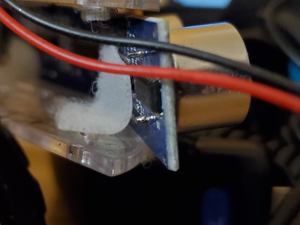
Connect the Reflectance Sensor
The reflectance sensor comes with some pins. Make sure those pins are soldered to the reflectance sensor.
Cut out a tiny piece of velcro and attach the reflectance sensor between the right and right-center HC-SR04 ultrasonic sensors.
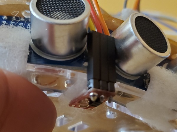
Wire the reflectance sensor exactly as shown in the circuit diagram.
Test Your Reflectance Sensor
Upload this code to your Arduino:
/**
* Addison Sears-Collins
* March 25, 2020
* This code is used to test the QTR-1A Reflectance Sensor
**/

/*---------------------------Definitions-------------------------------------*/
//Define pin for the QTR-1A Reflectance Sensor
#define IR_SENSOR A3

/*---------------------------Helper-Function Prototypes----------------------*/
void blinkLED(void);
int readIRSensor(void);

/*---------------------------Module Variables--------------------------------*/
// Store sensor readings here
int ir_reflect_previous;
int ir_reflect_current;

// Try values between 100 and 600.
// Helps determine if the robot crosses the reflective tape
int threshold = 200;

// Keep track of the number of times the robot crosses over
// the reflective tape
int stage = 0;

void setup() {

  // initialize digital pin LED_BUILTIN as an output.
  pinMode(LED_BUILTIN, OUTPUT);

  // Setup serial communication
  Serial.begin(9600);

  // Get initial readings on the reflectance sensor
  ir_reflect_previous = readIRSensor();
  ir_reflect_current = ir_reflect_previous;
}

void loop() {

  // Read the reflectance sensor
  ir_reflect_current = readIRSensor();

  // Check to see if we have crossed over the reflective tape
  if ((ir_reflect_previous - ir_reflect_current) >= threshold) {

    blinkLED();

    // Update the number of crosses
    stage = stage + 1;

    // Print the stage
    Serial.println("----------------------------------------");
    Serial.println((String)"Stage: " + stage);
    Serial.println("----------------------------------------");
  }

  // Print the readings
  Serial.println((String)"Previous: " + ir_reflect_previous);
  Serial.println((String)"Current: " + ir_reflect_current);
  Serial.println("");

  // Update the previous reading
  ir_reflect_previous = ir_reflect_current;

  delay(500);
}

void blinkLED(){
  for (int i = 0; i < 5; i++) {
    digitalWrite(LED_BUILTIN, HIGH);   // turn the LED on
    delay(50);                       // wait for half a second
    digitalWrite(LED_BUILTIN, LOW);    // turn the LED off
    delay(50);                       // wait for half a second
  }
}

int readIRSensor(){
  /*
   * Returns the sensor reading
   */
  int temp_reading = 0;
  int average = 0;

  // Grab four measurements and calculate the average
  for (int i = 0; i < 4; i++) {

    temp_reading = analogRead(IR_SENSOR);

    // Compute running sum
    average += temp_reading;

    delayMicroseconds(2);
  }

  // Return the average
  return (average / 4);
}
Click the magnifying glass in the upper right corner of the Arduino IDE. You should see the reflectance sensor readings printing out to the screen.
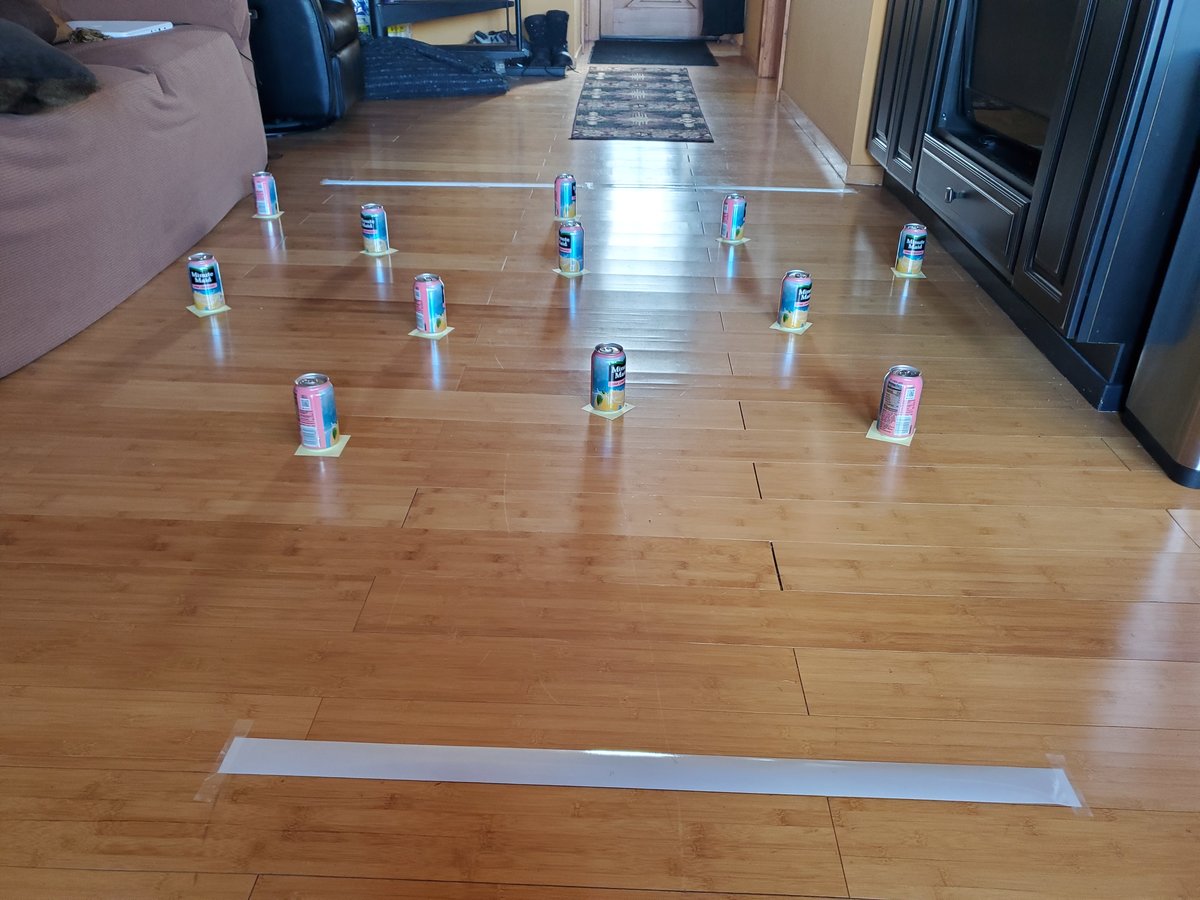
Set Up Your Obstacle Course
Now let’s set up the obstacle course.
Starting Line
Place a long piece of 3M silver reflective tape down on the floor. This is the starting line. As soon as the robot detects this tape, it will begin detecting obstacles (i.e. pink lemonade cans in my case).
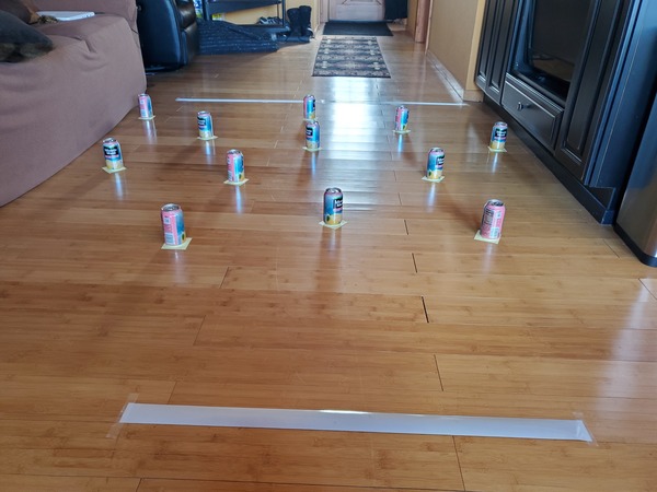
Finish Line
15-20 feet away from the Starting Line, place a long piece of 3M silver reflective tape down on the floor. This is the finish line. As soon as the robot detects this tape, it will begin maintaining the same heading it had when it crossed the Starting line. It will maintain this heading for two seconds before coming to a complete stop.
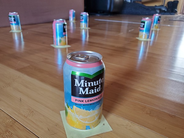
Multi-Obstacle Environment
Place a bunch of soda cans within your course…before the finish line, but after the starting line. Make sure the cans are at least 18 inches apart from each other.
Upload the Final Code
Now go back to your computer and upload the following code to your Arduino. If you’re interested in understanding what is going on inside the code, just go through it one line at a time, starting from the top, reading all my comments along the way.
#include <Wire.h> // Library for the BNO055
#include <Adafruit_Sensor.h> // Library for the BNO055
#include <Adafruit_BNO055.h> // Library for the BNO055
#include <utility/imumaths.h> // Library for the BNO055

/**
* Addison Sears-Collins
* April 3, 2020
* This code enables a robot to navigate through
* a multi-obstacle environment (MOE).
* The robot starts detecting obstacles once it crosses
* 3M silver reflective tape. The robot finishes once it
* crosses 3M silver reflective tape for the second time.
*
* To calibrate the BNO055 Orientation Sensor,
* start out with the robot facing
* due North (0 degrees).
**/

/*----------Definitions----------*/
//Define pins for Motor A
#define ENABLE_A 5
#define MOTOR_A1 6
#define MOTOR_A2 4

// Define pins for Motor B
#define ENABLE_B 8
#define MOTOR_B1 7
#define MOTOR_B2 9

// Define pin for the QTR-1A Reflectance Sensor
#define IR_SENSOR A3

// Right sensor
#define TRIG_RIGHT A2
#define ECHO_RIGHT A1

// Right-center sensor
#define TRIG_RIGHT_CTR 12
#define ECHO_RIGHT_CTR 13

// Left-center sensor
#define TRIG_LEFT_CTR 10
#define ECHO_LEFT_CTR 11

// Left sensor
#define TRIG_LEFT 3
#define ECHO_LEFT 2

// Avoidance delay
// Number of 50ms increments we want
// to move forward after
// moving away from the object
/***** Try 1-5 depending on battery strength********/
#define AVOIDANCE_DELAY 1

/*---Helper-Function Prototypes---*/
// Motors
void disableMotors(void);
void enableMotors(void);
void goForward(void);
void goLeft(void);
void goRight(void);
void leftAvoid(void);
void rightAvoid(void);

void setupPins(void);

// Headings
void calculateHeadingError(void);
void correctHeading(void);

// Ultrasonic sensors
void doPingRight(void);
void doPingRightCtr(void);
void doPingLeftCtr(void);
void doPingLeft(void);
void getDistances(void);

// IR sensor
void readIRSensor(void);

// Obstacle avoidance
void avoidObstacles(void);

/*--------Module Variables--------*/
bool crossed_the_tape = false;
bool done = false;

// Keep track of the headings
int desired_heading;
int current_heading;
int heading_threshold = 60; // 120 degree cone until stage 2
int heading_error;

// Store sensor readings here
int ir_reflect_previous;
int ir_reflect_current;

// Try values between 100 and 600.
// Helps determine if the robot crosses the reflective tape
int threshold = 200;

// For Ultrasonic sensor distance readings
int distance_right;
int distance_rightctr;
int distance_leftctr;
int distance_left;
int limit = 9; // Inches, try 5-10 depending on battery strength
bool right_or_left = false; // Switch

// Keep track of the time in milliseconds
unsigned long start_time;
unsigned long time_elapsed_threshold = 2000;

Adafruit_BNO055 bno = Adafruit_BNO055(55);

/*----------Module Code-----------*/
void setup(void) {

  // Start the car
  setupPins();
  enableMotors();

  // Get initial readings on the IR sensor
  ir_reflect_previous = analogRead(IR_SENSOR);
  ir_reflect_current = ir_reflect_previous;

  // Initialize the orientation sensor
  if(!bno.begin()) {
    // There was a problem detecting the
    // BNO055 ... check your connections
    //Serial.print("Ooops, no BNO055 detected ");
    //Serial.print("... Check your wiring or I2C ADDR!");
    while(1);
  }
  bno.setExtCrystalUse(true);
}

void loop(void) {

  // Stage 0 - before the robot enters the
  // multi-obstacle environment
  while(!crossed_the_tape) {

    delay(50);

    // Read desired heading
    sensors_event_t event;
    bno.getEvent(&event);
    desired_heading = event.orientation.x;

    goForward();

    readIRSensor();
  }

  crossed_the_tape = false;

  // Stage 1
  while(!crossed_the_tape) {

    // Read all four HC-SR04 sensors
    getDistances();

    // Avoid any obstacle along the way
    avoidObstacles();
  }

  heading_threshold = 10;

  // Capture the time
  start_time = millis();

  // Stage 2
  while(!done) {

    calculateHeadingError();

    // Correct the heading if needed
    if (abs(heading_error) <= abs(heading_threshold)){
      goForward();
    }
    else {
      correctHeading();
      goForward();
    }

    // Check to see if we are done
    if (((millis()) - start_time) > time_elapsed_threshold) {
      done = true;
    }
  }

  while(done) {
    disableMotors();
    delay(1000);
  }

}

void avoidObstacles(){
  // Avoid any objects
  if ((distance_leftctr < limit) && (distance_rightctr < limit)){

    // Switch back and forth
    if (right_or_left) {
      rightAvoid();
    }
    else {
      leftAvoid();
    }
    right_or_left = !(right_or_left);
  }
  else if((distance_left < limit) || (distance_leftctr < limit)) {
    rightAvoid();
  }
  else if((distance_right < limit) || (distance_rightctr < limit)) {
    leftAvoid();
  }
  else {
    calculateHeadingError();

    // Correct the heading if needed
    if (abs(heading_error) <= abs(heading_threshold)){
        goForward();
    }
    else {
      correctHeading();
      goForward();
    }
    // Check to see if we have crossed the tape
    readIRSensor();
    delay(50);
  }
}

void calculateHeadingError() {
  // Read the current heading
  sensors_event_t event;
  bno.getEvent(&event);
  current_heading = event.orientation.x;

  // Calculate the heading error
  heading_error = current_heading - desired_heading;
  if (heading_error > 180) {
      heading_error -= 360;
  }
  if (heading_error < -180) {
      heading_error += 360;
  }
}

void correctHeading(){
  // Turn the vehicle until it is facing the correct
  // direction
  if (heading_error < -heading_threshold) {
    while (heading_error < -heading_threshold) {
      goRight();
      delay(4);
      calculateHeadingError();
    }
  }
  else {
    while (heading_error > heading_threshold) {
      goLeft();
      delay(4);
      calculateHeadingError();
    }
  }
}

void doPingRight() {
  /*
   * Returns the distance to the obstacle as an integer in inches
   */
  // Make the Trigger LOW (0 volts) for 2 microseconds
  digitalWrite(TRIG_RIGHT, LOW);
  delayMicroseconds(2);

  // Emit high frequency 40kHz sound pulse
  // (i.e. pull the Trigger)
  // by making Trigger HIGH (5 volts)
  // for 10 microseconds
  digitalWrite(TRIG_RIGHT, HIGH);
  delayMicroseconds(10);
  digitalWrite(TRIG_RIGHT, LOW);

  // Detect a pulse on the Echo pin.
  // pulseIn() measures the time in
  // microseconds until the sound pulse
  // returns back to the sensor.
  distance_right = pulseIn(ECHO_RIGHT, HIGH);

  // Speed of sound is:
  // 13511.811023622 inches per second
  // 13511.811023622/10^6 inches per microsecond
  // 0.013511811 inches per microsecond
  // Taking the reciprocal, we have:
  // 74.00932414 microseconds per inch
  // Below, we convert microseconds to inches by
  // dividing by 74 and then dividing by 2
  // to account for the roundtrip time.
  distance_right = distance_right / 74 / 2;
  distance_right = abs(distance_right);
}

void doPingRightCtr(){
  /*
   * Returns the distance to the obstacle as an integer in inches
   */

  // Make the Trigger LOW (0 volts) for 2 microseconds
  digitalWrite(TRIG_RIGHT_CTR, LOW);
  delayMicroseconds(2);

  // Emit high frequency 40kHz sound pulse
  // (i.e. pull the Trigger)
  // by making Trigger HIGH (5 volts)
  // for 10 microseconds
  digitalWrite(TRIG_RIGHT_CTR, HIGH);
  delayMicroseconds(10);
  digitalWrite(TRIG_RIGHT_CTR, LOW);

  // Detect a pulse on the Echo pin.
  // pulseIn() measures the time in
  // microseconds until the sound pulse
  // returns back to the sensor.
  distance_rightctr = pulseIn(ECHO_RIGHT_CTR, HIGH);

  // Speed of sound is:
  // 13511.811023622 inches per second
  // 13511.811023622/10^6 inches per microsecond
  // 0.013511811 inches per microsecond
  // Taking the reciprocal, we have:
  // 74.00932414 microseconds per inch
  // Below, we convert microseconds to inches by
  // dividing by 74 and then dividing by 2
  // to account for the roundtrip time.
  distance_rightctr = distance_rightctr / 74 / 2;
  distance_rightctr = abs(distance_rightctr);
}

void doPingLeftCtr(){
  /*
   * Returns the distance to the obstacle as an integer in inches
   */

  // Make the Trigger LOW (0 volts) for 2 microseconds
  digitalWrite(TRIG_LEFT_CTR, LOW);
  delayMicroseconds(2);

  // Emit high frequency 40kHz sound pulse
  // (i.e. pull the Trigger)
  // by making Trigger HIGH (5 volts)
  // for 10 microseconds
  digitalWrite(TRIG_LEFT_CTR, HIGH);
  delayMicroseconds(10);
  digitalWrite(TRIG_LEFT_CTR, LOW);

  // Detect a pulse on the Echo pin.
  // pulseIn() measures the time in
  // microseconds until the sound pulse
  // returns back to the sensor.
  distance_leftctr = pulseIn(ECHO_LEFT_CTR, HIGH);

  // Speed of sound is:
  // 13511.811023622 inches per second
  // 13511.811023622/10^6 inches per microsecond
  // 0.013511811 inches per microsecond
  // Taking the reciprocal, we have:
  // 74.00932414 microseconds per inch
  // Below, we convert microseconds to inches by
  // dividing by 74 and then dividing by 2
  // to account for the roundtrip time.
  distance_leftctr = distance_leftctr / 74 / 2;
  distance_leftctr = abs(distance_leftctr);
}

void doPingLeft(){
  /*
   * Returns the distance to the obstacle as an integer in inches
   */

  // Make the Trigger LOW (0 volts) for 2 microseconds
  digitalWrite(TRIG_LEFT, LOW);
  delayMicroseconds(2);

  // Emit high frequency 40kHz sound pulse
  // (i.e. pull the Trigger)
  // by making Trigger HIGH (5 volts)
  // for 10 microseconds
  digitalWrite(TRIG_LEFT, HIGH);
  delayMicroseconds(10);
  digitalWrite(TRIG_LEFT, LOW);

  // Detect a pulse on the Echo pin.
  // pulseIn() measures the time in
  // microseconds until the sound pulse
  // returns back to the sensor.
  distance_left = pulseIn(ECHO_LEFT, HIGH);

  // Speed of sound is:
  // 13511.811023622 inches per second
  // 13511.811023622/10^6 inches per microsecond
  // 0.013511811 inches per microsecond
  // Taking the reciprocal, we have:
  // 74.00932414 microseconds per inch
  // Below, we convert microseconds to inches by
  // dividing by 74 and then dividing by 2
  // to account for the roundtrip time.
  distance_left = distance_left / 74 / 2;
  distance_left = abs(distance_left);
}

void getDistances() {
  // Take distance readings on the HC-SR04
  doPingRight();
  doPingLeftCtr();
  doPingRightCtr();
  doPingLeft();
}

void disableMotors(){
  digitalWrite(ENABLE_A, LOW);
  digitalWrite(ENABLE_B, LOW);
}

void enableMotors(){
  digitalWrite(ENABLE_A, HIGH);
  digitalWrite(ENABLE_B, HIGH);
}

void goForward(){
  digitalWrite(MOTOR_A1, LOW);
  digitalWrite(MOTOR_A2, HIGH);
  digitalWrite(MOTOR_B1, LOW);
  digitalWrite (MOTOR_B2, HIGH);
}

void goLeft(){
  digitalWrite(MOTOR_A1, LOW);
  digitalWrite(MOTOR_A2, HIGH);
  digitalWrite(MOTOR_B1, HIGH);
  digitalWrite (MOTOR_B2, LOW);
}

void goRight(){
  digitalWrite(MOTOR_A1, HIGH);
  digitalWrite(MOTOR_A2, LOW);
  digitalWrite(MOTOR_B1, LOW);
  digitalWrite (MOTOR_B2, HIGH);
}

void leftAvoid(){
  // Go to the left when an object is detected
  // on the right-side of the vehicle
  while((distance_right < limit) || (distance_rightctr < limit)) {
    goLeft();
    delay(4);
    doPingRight();
    doPingRightCtr();
  }
  goForward();

  for (int i = 0; i < AVOIDANCE_DELAY; i++) {
    // Read the reflectance sensor
    ir_reflect_current = analogRead(IR_SENSOR);

    // Check to see if we have crossed over the reflective tape
    if ((ir_reflect_previous - ir_reflect_current) >= threshold) {

      // Update if we crossed the tape
      crossed_the_tape = true;

      break;
    }
    // Update the previous reading
    ir_reflect_previous = ir_reflect_current;

    delay(50);
  }
}

void readIRSensor() {

  // Read the reflectance sensor
  ir_reflect_current = analogRead(IR_SENSOR);

  // Check to see if we have crossed over the reflective tape
  if ((ir_reflect_previous - ir_reflect_current) >= threshold) {

    // Update if we crossed the tape
    crossed_the_tape = true;
  }
  // Update the previous reading
  ir_reflect_previous = ir_reflect_current;
}

void rightAvoid(){
  // Go to the right when an object is detected
  // on the left-side of the vehicle
  while((distance_left < limit) || (distance_leftctr < limit)) {
    goRight();
    delay(4);
    doPingLeft();
    doPingLeftCtr();
  }
  goForward();

  for (int i = 0; i < AVOIDANCE_DELAY; i++) {
    // Read the reflectance sensor
    ir_reflect_current = analogRead(IR_SENSOR);

    // Check to see if we have crossed over the reflective tape
    if ((ir_reflect_previous - ir_reflect_current) >= threshold) {

      // Update if we crossed the tape
      crossed_the_tape = true;

      break;
    }
    // Update the previous reading
    ir_reflect_previous = ir_reflect_current;

    delay(50);
  }
}

void setupPins(){
  // Configure motor pins
  pinMode(ENABLE_A, OUTPUT);
  pinMode(MOTOR_A1, OUTPUT);
  pinMode(MOTOR_A2, OUTPUT);
  pinMode(ENABLE_B, OUTPUT);
  pinMode(MOTOR_B1, OUTPUT);
  pinMode(MOTOR_B2, OUTPUT);

  // Configure HC-SR04 pins
  pinMode(TRIG_RIGHT, OUTPUT);
  pinMode(ECHO_RIGHT, INPUT);
  pinMode(TRIG_RIGHT_CTR, OUTPUT);
  pinMode(ECHO_RIGHT_CTR, INPUT);
  pinMode(TRIG_LEFT_CTR, OUTPUT);
  pinMode(ECHO_LEFT_CTR, INPUT);
  pinMode(TRIG_LEFT, OUTPUT);
  pinMode(ECHO_LEFT, INPUT);
}
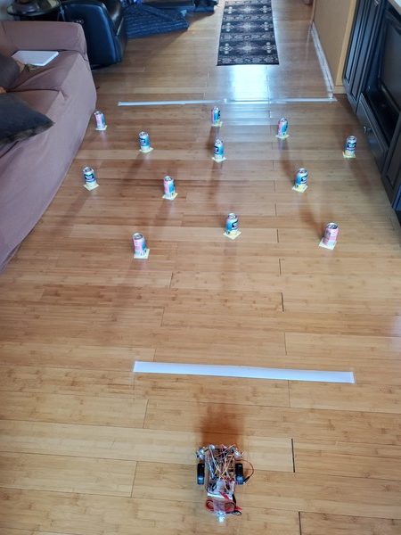
Deploy Your Robot
Now, we’ve come to the time you’ve been waiting for. It’s time to move the robot through the obstacle course from start to finish.
Set your robot on the floor 3-5 feet before the starting line.
Plug in the Arduino, and within a second or two, you should see your robot take off, moving through the obstacle all by itself! Two seconds after it crosses the finish line, it should come to a complete stop.
Video
Troubleshooting
If your robot is not moving through the obstacle course, go back to the beginning of this post and make sure that everything is wired up and connected as I have shown.
Also, you can try tweaking the defined constants in the final code to see if your robot behaves better.
That’s it for now. Congratulations, you have built an autonomous mobile robot from scratch that can sense, think, and act.
Keep building!