
In this tutorial, we will program our robot to perform a pick and place task.
Pick and place involves picking up an object in one location and placing it in another.
In this case, we will have our do-it-yourself SCARA robotic arm pick up a hex nut in one location and drop it off in another. Take a look at the video below of what you will build.
Real-World Applications
SCARA robots have a number of real-world applications:
- Manufacturing: Picking up items off a conveyor belt and dropping them off on another conveyor belt.
- Logistics: Picking up an item and placing it in a bin.
- Factory: Tightening screws.
You can see an image here of a SCARA robot packaging cookies into bins.
Prerequisites
- You completed this tutorial to build a two degree of freedom robotic arm.
You Will Need
Assuming you have gone through the prerequisites and acquired all the components in there, you will also need the following components to complete this project (#ad):
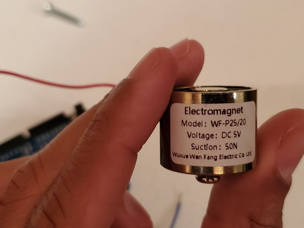
- 5V or 6V Electric Lifting Magnet (electromagnet to pick up the nut)
- Actuonix L16 Actuator 100mm 150:1 6V RC Control (linear actuator…check on eBay for this)
- 22 gauge wire spool (to tie the actuator to the end of the end effector of the robotic arm)
- Small Hex Nut or a Screw (any size is OK) or Any Small Object Made of Metal
- 5V Relay (only needed if you’re going to buy the 6V Electric Lifting Magnet)
- 6 Channel Servo Tester
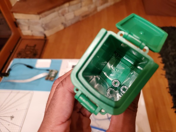
- Toy Trash Can
- 2 x Oblique U-type Robotic Arm Brackets (check eBay and Amazon)
- M3 Screws and Nuts (3mm in diameter screws)
- VELCRO Brand Thin Clear Dots with Adhesive
Connect and Test the Linear Actuator
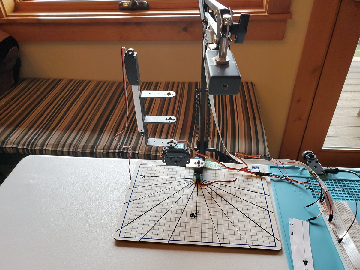
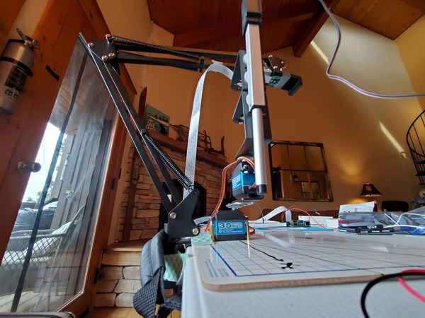
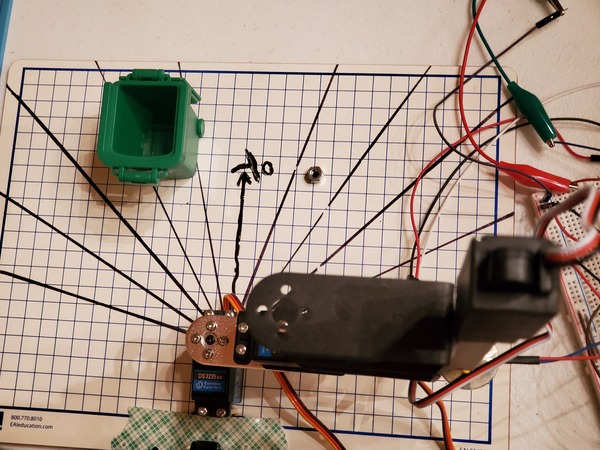
The first thing you need to do is to replace the upper link of the robot arm with U-type robotic arm brackets.
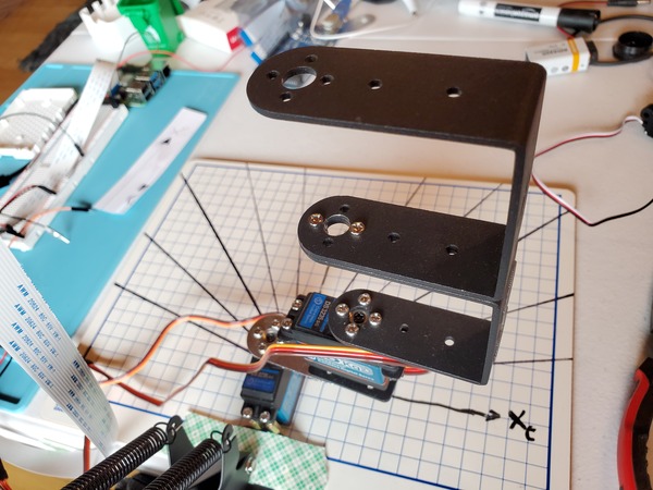
Attach the linear actuator to the brackets using VELCRO Brand Thin Clear Dots with Adhesive. My setup looks like this:
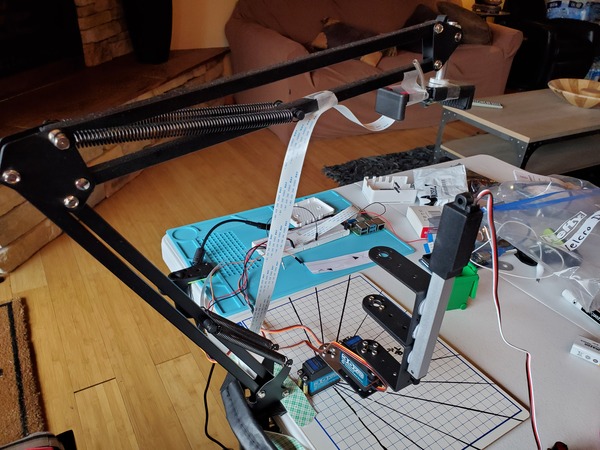
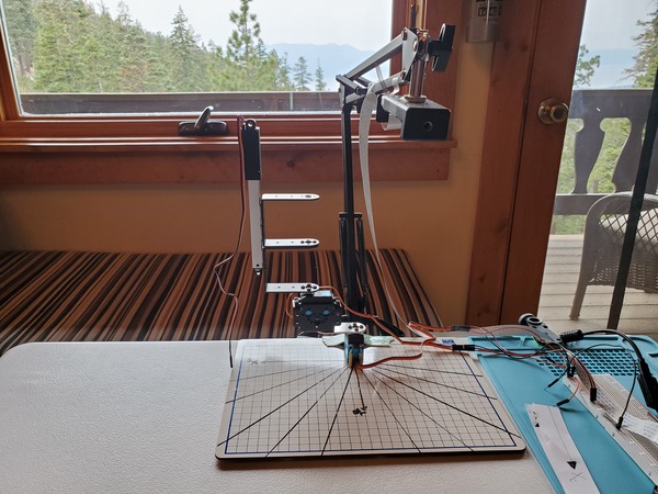
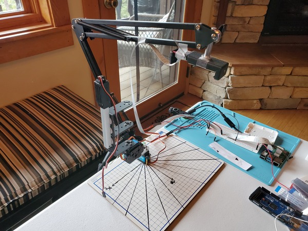
We now have our very own SCARA-style robot.
Let’s test it. The linear actuator has the following specifications:
- Input voltage: 5-7.4V
- Stall current: 650mA
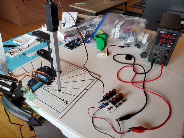
Grab the 6 channel digital servo tester.
Connect the positive red lead to the positive terminal of the power supply.
Connect the negative black lead to the negative terminal of the power supply.
Connect the linear actuator to the digital servo tester so that the:
- Black lead connects to (-)
- Red lead connects to (+)
- White lead connects to (S), which means signal
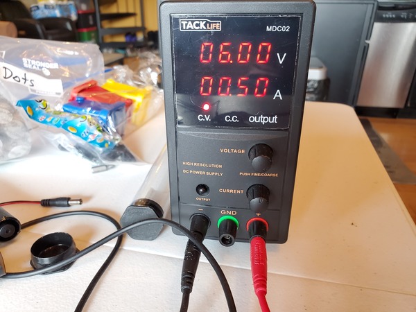
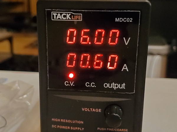
Now turn on the power supply. Set it to 6.0V with a current limit of 0.50A (ie. 500mA).
Turn the corresponding knob on the digital servo tester, and watch the linear actuator go back and forth.
Control the Linear Actuator Using Arduino
Now we want to write code so that we can automatically control the lowering and raising of the linear actuator. We will write code that makes the linear actuator go back and forth repeatedly.
Open your Arduino IDE, and type the following code. Save the file as control_linear_actuator.ino.
/*
Program: Make a linear actuator go back and forth automatically
File: control_linear_actuator.ino
Description: This program makes the Actuonix L16 Actuator 100mm 150:1 6V RC Control
  go back and forth.
Author: Addison Sears-Collins
Website: https://automaticaddison.com
Date: October 5, 2020
*/

#include <VarSpeedServo.h>

//////////// Linear Actuator Variables ///////////////
// Create the object.
VarSpeedServo linearActuator;

// Attach motor to digital pin on the Arduino
const int linearActuatorPin = 12;

// Set the home and extended positions of the linear actuator
const int linearActuatorHomePos = 0;
const int linearActuatorExtPos = 180;

// Stores the current position of the linear actuator
int linearActuatorPos = 0;

// The amount of time in milliseconds alloted to enable the linear actuator to move into position
// The more delay given, the more the linear actuator extends. 100ms, for example, will result
// in full extension of the linear actuator.
const int linearActuatorDelay = 50;
//////////// End Linear Actuator Variables ///////////////

void setup() {

    // Attach the linear actuator to the pin
    linearActuator.attach(linearActuatorPin);
}

void loop() {

  // Linear actuator goes to extended position and then back to home position
  moveLinearActuator();
}

void moveLinearActuator() {

  for (linearActuatorPos = linearActuatorHomePos; linearActuatorPos <= linearActuatorExtPos; linearActuatorPos += 1) { // goes from home position to extended position
    linearActuator.write(linearActuatorPos);
    delay(linearActuatorDelay);  // wait for the actuator to reach the position
  }
  for (linearActuatorPos = linearActuatorExtPos; linearActuatorPos >= linearActuatorHomePos; linearActuatorPos -= 1) { // goes from extended position to home position
    linearActuator.write(linearActuatorPos);
    delay(linearActuatorDelay);  // wait for the actuator to reach the position
  }
}
Wire the linear actuator to the Arduino Mega 2560 like what is shown in wiring_linear_actuator_v2.pdf.
Turn on the power supply (6.0V with a current limit of 0.50A), and then plug in the Arduino to the 9V battery. Watch the linear actuator go back and forth.
So that you don’t damage your Arduino Mega, turn off the DC external power supply first before unplugging the Arduino.
Test the Electric Lifting Magnet
Now that we’ve tested the linear actuator, let’s test the electric lifting magnet.
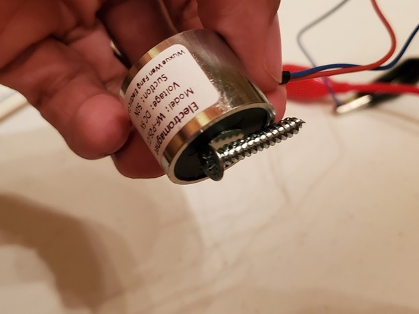
Grab the electric lifting magnet.
Attach the positive (typically red) lead of the magnet to the red positive lead of the power supply.
Attach the other lead (typically blue or black) of the magnet to the black lead of the power supply.
Set the voltage to 5V (or 6V depending on what it says on your magnet) and the current limit to 0.50A (the current limit of this component is 0.68A).
Turn on the power supply.
Grab a small metal object like a screw or hex nut, and place it near the magnet.
You should see the hex nut move towards the magnet.
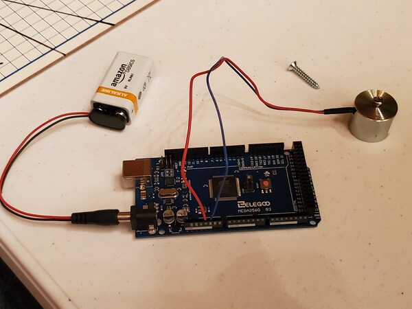
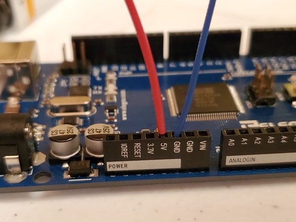
If you are using a 5V electric lifting magnet, you can power the magnet directly with the Arduino by placing the leads in the 5V and GND (ground) pins.
Control the Electric Lifting Magnet Using Arduino
Now let’s control the electric lifting magnet using Arduino.
Using a 6V Electric Lifting Magnet
If you have a 6V electric lifting magnet, follow the instructions in this section. Otherwise, if you’re using a 5V electric lifting magnet, proceed to the next section.
Grab the 5V Relay. This relay acts as a switch for the electric lifting magnet, enabling you to activate and deactivate the magnetism using Arduino.
There are 6 pins on the relay:
- NO: Normally Open Terminal (peak load of DC28~30V/10A)
- NC: Normally Closed Terminal
- COM: Common Terminal
- DC+: Connects to the 5V pin (power supply) of the Arduino
- DC-: Connects to the GND (ground) pin of the Arduino
- IN: Control pin that receives either a HIGH (3-5V) or LOW (0-1.5V) signal from the Arduino (Pin 10 in our case)
If you decide to use the NO terminal instead of the NC terminal, when a HIGH signal is received on the IN pin from the Arduino, the relay switch will turn ON, allowing electric current to flow from C to NO. We’ll use this NO terminal in our work.
If you decide to use the NC terminal instead of the NO terminal, when a LOW signal is received on the IN pin from the Arduino, the relay switch will turn ON allowing electric current to flow from C to NC.
Here is how to wire the relay: control_electric_magnet_arduino_v1.pdf.
Here is the code to test the setup: control_electric_magnet_arduino_v1.ino.
/*
Program: Make an electric lifting magnet turn ON and OFF repeatedly.
File: control_electric_magnet_arduino_v1.ino
Description: This program makes an electric lifting magnet turn ON and OFF repeatedly.
Author: Addison Sears-Collins
Website: https://automaticaddison.com
Date: October 6, 2020
*/

const int magnetSignalPin = 10;    // select the pin that will control the magnet

void setup() {
  pinMode(magnetSignalPin, OUTPUT);    // sets digital pin 10 as output
}

void loop() {
  activateMagnet();
  delay(10000);            // waits for 10 seconds
  deactivateMagnet();
  delay(3000);            // wait for 3 seconds
}

void activateMagnet() {
  digitalWrite(magnetSignalPin, HIGH); // sets the digital pin ON
}

void deactivateMagnet() {
  digitalWrite(magnetSignalPin, LOW); // sets the digital pin OFF
}
Using a 5V Electric Lifting Magnet
If you’re using the 5V electric lifting magnet, wire your system as follows: control_electric_magnet_arduino_v2.pdf.
For your Arduino, you’ll need to upload the same code from the previous section: control_electric_magnet_arduino_v1.ino.
Your magnet will activate for 10 seconds and then deactivate for 3 seconds.
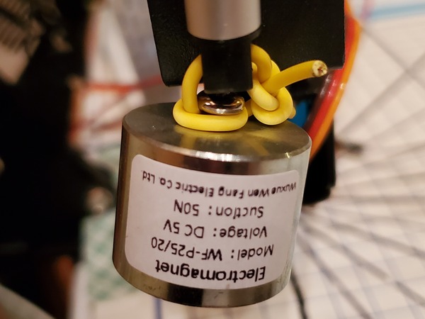
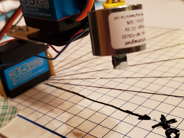
Connect the Electric Lifting Magnet to the Linear Actuator
Now that we’ve tested the electric lifting magnet, let’s connect it to the end of the linear actuator. I placed a 3mm diameter screw in one side of the magnet so that it can more easily attach to the end of the linear actuator.
Perform Pick and Place Using Arduino
Before we dive into the pick and place task, let’s see how to perform pick and place using Arduino and our robotic arm. Check out this tutorial for the details on the math.
What we want to do is:
- Place a hex nut at a predetermined x and y coordinate. This is the pick location.
- Move the end effector to the pick location.
- Activate the electric lifting magnet.
- Lower the linear actuator.
- Pick up the hex nut.
- Raise the linear actuator.
- Move the end effector to the place location.
- Deactivate the electric lifting magnet.
- Place the hex nut in the toy trash can by lowering the actuator.
- Return to the home position (both servos at 0 degrees).
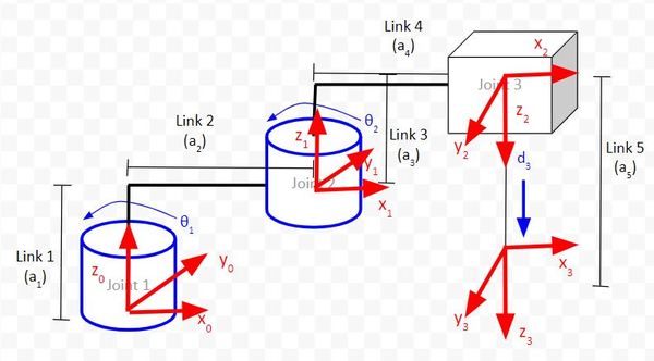
To get started, measure the link lengths, a1, a2, a3, and a4. Use the kinematic diagram below as your guide. You’ll need to use a ruler for this.
- a1 is measured vertically from the board’s surface to the top of Link 2.
- a2 is measured horizontally from the middle of the first servo (where the central screw is located on Joint 1) to the middle of the second servo (where the central screw on Joint 2 is located).
- a3 is measured vertically from the top of Link 2 to the top of Link 4.
- a4 is measured horizontally from the middle of the second servo to the middle of the electric lifting magnet.
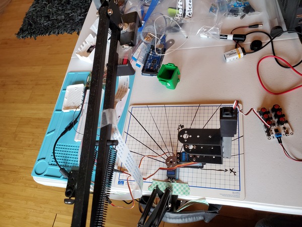
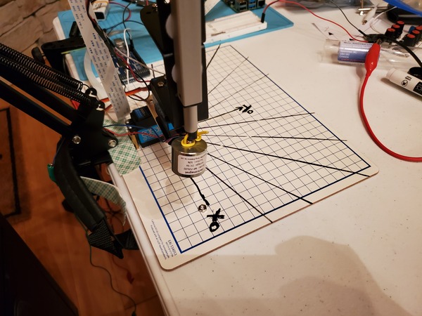
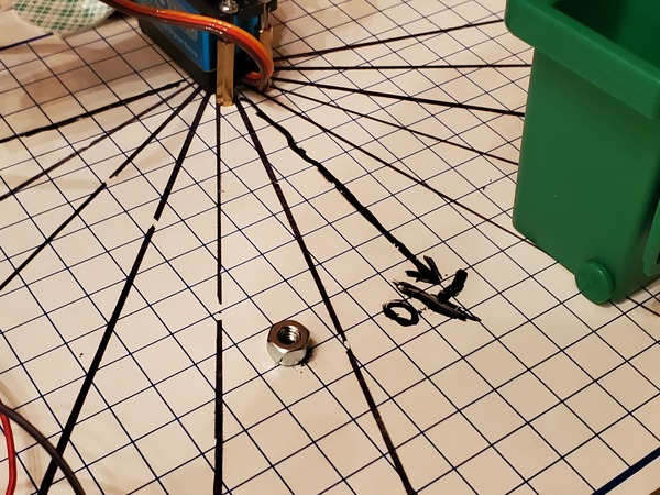
Place a metal object (e.g. hex nut) at position x = 4.0, y = 10.0 on the board.
Place the toy trash cash at position x = -4.0, y = 10.0.
Here is the wiring diagram: pick_and_place_no_vision_v1.pdf.
Set the power supply to 6V with a 0.60A current limit.
Here is the code for the Arduino: pick_and_place_no_vision.ino.
/*
Program: Perform a pick and place task with a SCARA-style robotic
  arm using inverse kinematics (graphical method)
File: pick_and_place_no_vision_v1.ino
Description: This program performs a pick and place task with a SCARA-style robotic arm.
  No computer vision is used.
Author: Addison Sears-Collins
Website: https://automaticaddison.com
Date: October 9, 2020
*/

#include <VarSpeedServo.h>

//////////// Servo Motor Variables ///////////////

// Define the number of servos
#define SERVOS 2

// Create the servo objects.
VarSpeedServo myservo[SERVOS];

// Speed of the servo motors
// Speed=1: Slowest
// Speed=255: Fastest.
const int servoSpeed = 50;

// Attach servos to digital pins on the Arduino
int servoPins[SERVOS] = {3,5};

//////////// End Servo Motor Variables ///////////////

//////////// Linear Actuator Variables ///////////////

// Create the linear servo object.
VarSpeedServo linearActuator;

// Attach motor to digital pin on the Arduino
const int linearActuatorPin = 12;

// Set the home position of the linear actuator
const int linearActuatorHomePos = 0;

// Stores the current position of the linear actuator
int linearActuatorPos = 0;

// The amount of time in milliseconds alloted to enable the linear actuator to move into position
// The more delay given, the more the linear actuator extends. 100ms, for example, will result
// in full extension of the linear actuator. Tweak this input here until you get desired results.
const int linearActuatorDelay = 45;

//////////// End Linear Actuator Variables ///////////////

// Link lengths in centimeters
const double a1 = 4.85;
const double a2 = 5.80;
const double a3 = 5.15;
const double a4 = 6.0;

// Select the pin that will control the magnet
const int magnetSignalPin = 10;

void setup() {

  // Move servos to the home position of 0 degrees
  setupServos();

  // Set magnet pin
  pinMode(magnetSignalPin, OUTPUT);

  // Attach the linear actuator to the digital pin of the Arduino
  linearActuator.attach(linearActuatorPin);
  linearActuator.write(0);
  delay(1000);
}

void loop() {

  // The pick location in centimeters in the
  // robot's base frame (pick up the object from here)
  double xPosPick = 4.0;
  double yPosPick = 10.0;

  // The place location in centimeters in the
  // robot's base frame (place the object here)
  double xPosPlace = -4.0;
  double yPosPlace = 10.0;

  // Pick up an object from one location, and place it in another
  pickAndPlace(xPosPick, yPosPick, xPosPlace, yPosPlace);

  while(1) {
    // Return home
    returnHome();
  }
}

/*  This method converts the desired angle for Servo 1 into a control angle
 *  for Servo 1. It assumes that the 0 degree position on the kinematic
 *  diagram for Servo 1 is actually 90 degrees on the actual servo.
 *  The angle range for Servo 1 on the kinematic diagram is
 *  -90 to 90 degrees, with 0 degrees being the center position.
 *  The actual servo range for the physical motor
 *  is 0 to 180 degrees. We convert the desired angle
 *  to a value within that range.
 */
int calcServo1Angle (int inputAngle) {

  int result;

  result = map(inputAngle, -90, 90, 0, 180);

  return result;
}

/* Move servos to the home position */
void setupServos() {

  // Attach the servos to the servo object
  // attach(pin, min, max  ) - Attaches to a pin
  //   setting min and max values in microseconds
  //   default min is 544, max is 2400
  // Alter these numbers until both servos have a
  //   180 degree range.
  myservo[0].attach(servoPins[0], 544, 2475);
  myservo[1].attach(servoPins[1], 500, 2475);

  // Set initial servo positions to home position
  myservo[0].write(0, servoSpeed, true);
  myservo[1].write(calcServo1Angle(0), servoSpeed, true);

  // Wait to let servos get into position
  delay(3000);
}

/* Move arm to the x and y position indicated by the parameters */
void moveArm(double xPos, double yPos) {

  // Define the inverse kinematics variables
  double r1 = 0.0;
  double phi_1 = 0.0;
  double phi_2 = 0.0;
  double phi_3 = 0.0;
  double theta_1 = 0.0;
  double theta_2 = 0.0;

  /* Calculate the inverse kinematics*/
  // (1) r1  = square_root((x_0_2)^2 + (y_0_2)^2)
  // Value is in centimeters
  r1 = sqrt((xPos * xPos) + (yPos * yPos));

  // (2) ϕ1 = arccos((a4^2 - r1^2 - a2^2)/(-2*r1*a2))
  // The returned value is in the range [0, pi] radians.
  phi_1 = acos(((a4 * a4) - (r1 * r1) - (a2 * a2))/(-2.0 * r1 * a2));

  // (3) ϕ2 = arctan((y_0_2) / (x_0_2))
  // The atan2() function computes the principal value of the
  // arc tangent of y/x, using the signs of both arguments to
  // determine the quadrant of the return value.
  // The returned value is in the range [-pi, +pi] radians.
  phi_2 = atan2(yPos, xPos);

  // (4) θ1 =  ϕ1 - ϕ2
  // Value is in radians
  theta_1 = phi_2 - phi_1;

  // (5) ϕ3 = arccos((r1^2 - a2^2 - a4^2)/(-2*a2*a4))
  // Value is in radians
  phi_3 = acos(((r1 * r1) - (a2 * a2) - (a4 * a4))/(-2.0 * a2 * a4));

  //(6) θ2 = 180° - ϕ3
  theta_2 = PI - phi_3;

  /* Convert the joint (servo) angles from radians to degrees*/
  theta_1 = theta_1 * RAD_TO_DEG; // Joint 1
  theta_2 = theta_2 * RAD_TO_DEG; // Joint 2

  /* Move the end effector to the desired x and y position */
  // Set Joint 1 (Servo 0) angle
  myservo[0].write(theta_1, servoSpeed, true);

  // Set Joint 2 (Servo 1) angle
  myservo[1].write(calcServo1Angle(theta_2), servoSpeed, true);

  // Wait
  delay(1000);
}

/* Activate the electric lifting magnet */
void activateMagnet() {
  digitalWrite(magnetSignalPin, HIGH); // sets the digital pin ON
}

/* Deactivate the electric lifting magnet */
void deactivateMagnet() {
  digitalWrite(magnetSignalPin, LOW); // sets the digital pin OFF
}

/* Move linear actuator down and then up */
void moveLinearActuator(int extension) {

  // goes from home position to extended position
  for (linearActuatorPos = linearActuatorHomePos; linearActuatorPos <= extension; linearActuatorPos += 1) {
    linearActuator.write(linearActuatorPos);
    delay(linearActuatorDelay);                       // wait for the actuator to reach the position
  }

  // goes from extended position to home position
  for (linearActuatorPos = extension; linearActuatorPos >= linearActuatorHomePos; linearActuatorPos -= 1) {
    linearActuator.write(linearActuatorPos);
    delay(linearActuatorDelay * 2);                          // wait for the actuator to reach the position
  }
}

/* Pick up an object from one location, and place it in another */
void pickAndPlace(double xPosPick, double yPosPick, double xPosPlace, double yPosPlace) {

  // Move arm to the pick location
  moveArm(xPosPick, yPosPick);

  activateMagnet();

  // Pick up the object
  moveLinearActuator(180);

  // Move arm to the place location
  moveArm(xPosPlace, yPosPlace);

  deactivateMagnet();

  // Place the object (tweak this input here until you get desired results)
  moveLinearActuator(120);

  delay(1000);
}

/* Return to the 0 degree home position */
void returnHome() {

  // Set servo positions to home position
  myservo[0].write(0, servoSpeed, true);
  myservo[1].write(calcServo1Angle(0), servoSpeed, true);
}
Future Challenge Project: Add Computer Vision to Automate Pick and Place
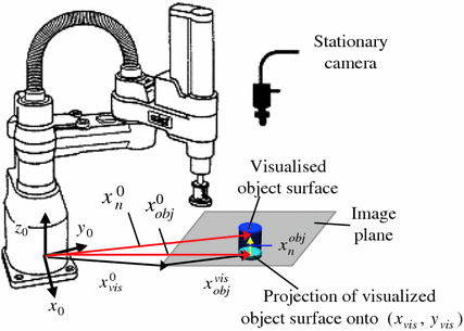
Up until now, we have placed an object at a predetermined location, and we hardcoded that location in our Arduino code. If you’re feeling really ambitious, what you can now do is integrate the Raspberry Pi camera so you can determine the object’s location automatically.
What you’ll want to do is:
- Turn on the Raspberry Pi camera.
- Place a hex nut on the board, somewhere where the camera can see it, and the robotic arm can reach it.
- Determine the coordinates of the object using the Raspberry Pi camera. This is the target location.
- Send the coordinates of that object (in the robot’s base frame) from Raspberry Pi to Arduino.
- Move the end effector to the target location.
- Activate the electric lifting magnet.
- Lower the linear actuator.
- Pick up the hex nut.
- Raise the linear actuator.
- Move the linear actuator to the toy trash can.
- Lower the linear actuator.
- Deactivate the electric lifting magnet.
- Place the hex nut.
- Raise the linear actuator.
- Return to the home position
- Pick and place complete!
You will need to tweak the code in this tutorial to get everything working.
That’s it for today. Keep building!
Disclosure (#ad): As an Amazon Associate, I earn from qualifying purchases.