

Once we have filled in the Denavit-Hartenberg (D-H) parameter table for a robotic arm, we find the homogeneous transformation matrices (also known as the Denavit-Hartenberg matrix) by plugging the values into the matrix of the following form, which is the homogeneous transformation matrix for joint n (i.e. the transformation from frame n-1 to frame n).
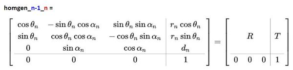
where R is the 3×3 submatrix in the upper left that represents the rotation from frame n-1 (e.g. frame 0) to frame n (e.g. frame 1), and T is the 3×1 submatrix in the upper right that represents the translation (or displacement) from frame n-1 to frame n.
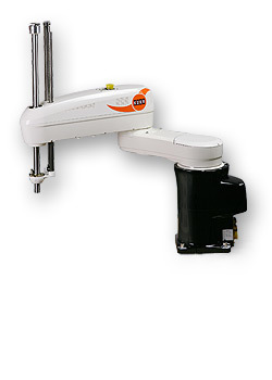
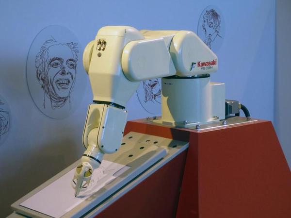
For example, suppose we have a SCARA robotic arm.

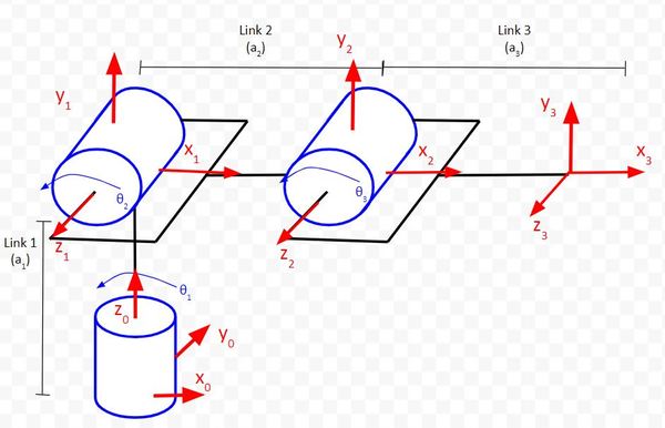
We draw the kinematic diagram for this arm.
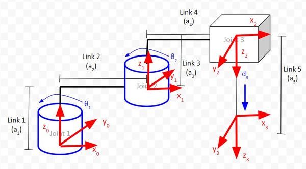
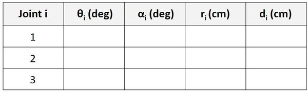
We then use that diagram to find the Denavit-Hartenberg parameters:
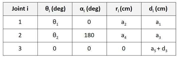
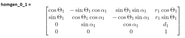
We now want to find the homogeneous transformation matrix from frame 0 to frame 1, so we look at the first row of the Denavit-Hartenberg parameter table labeled ‘Joint 1’ (remember that a joint in our case is either a servo motor that produces rotational motion or a linear actuator that produces linear motion).
In this case, n=1, and we would look at the first row of the D-H table (Joint 1) and plug in the appropriate values into the following matrix:
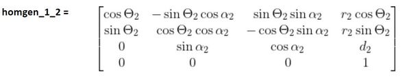
For the homogeneous transformation matrix from frame 1 to 2, we would look at the second row of the D-H table (Joint 2) and plug in the corresponding values into the following matrix.
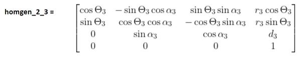
For the homogeneous transformation matrix from frame 2 to 3, we would look at the third row of the table (Joint 3) and plug in the corresponding values into the following matrix.
Then, to find the homogeneous transformation matrix from the base frame (frame 0) to the end-effector frame (frame 3), we would multiply all the transformation matrices together.
homgen_0_3 = (homgen_0_1)(homgen_1_2)(homgen_2_3)
Let’s take a look at some examples.
Example 1 – Cartesian Robot
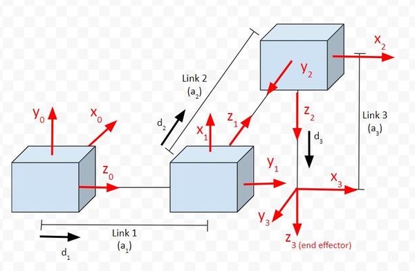
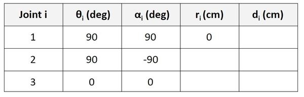
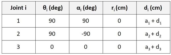
We have four reference frames, so we need to have three rows in our Denavit-Hartenberg parameter table.
Let’s begin by looking at the first column of the table.
Find θ
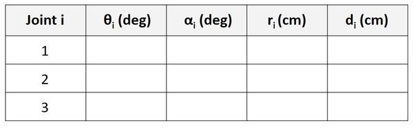
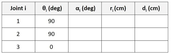
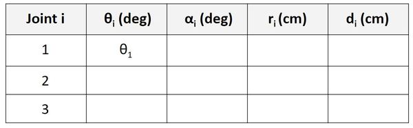
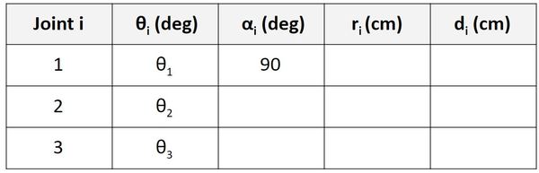
For the Joint 1 row (Servo 0), we are going to focus on the relationship between frame 0 and frame 1. θ is the angle from x0 to x1 around z0.
If you look at the diagram, take the thumb of your right hand and stick it in z0 direction. Your fingers curl in the direction of positive rotation. The angle from x0 to x1 around z0 is 90 degrees in the counterclockwise (i.e. positive) direction. This angle won’t change regardless of how the linear actuator at frame 0 moves in the d1 direction.
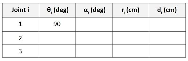
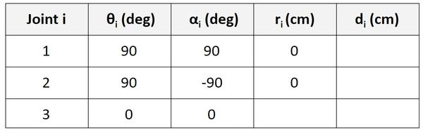
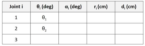
Now, let’s look at the Joint 2 row. We take a look at the rotation between frame 1 and frame 2. θ is the angle from x1 to x2 around z1.
If you look at the diagram, take the thumb of your right hand and stick it in z1 direction. Your fingers curl in the direction of positive rotation. The angle from x1 to x2 around z1 is 90 degrees in the counterclockwise (i.e. positive) direction. This angle won’t change regardless of how the linear actuator at frame 1 moves in the d2 direction.
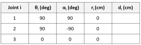
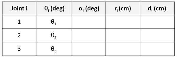
Now, let’s look at the Joint 3 row. We take a look at the rotation between frame 2 and frame 3. θ is the angle from x2 to x3 around z2.
If you look at the diagram, x2 and x3 both point in the same direction. The axes are therefore aligned. When the robot is in motion, there is only linear motion along z2. The angle from x2 to x3 around z2 will remain 0, so let’s put that in the third row of our table.
Find α
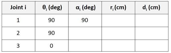
Let’s start with the Joint 1 row of the table.
α is the angle from z0 to z1 around x1.
Take your right thumb and point it in the x1 direction. Curl your fingers counterclockwise from z0 to z1. The angle is 90 degrees.
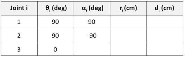
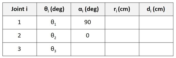
Let’s go to the Joint 2 row of the table.
α is the angle from z1 to z2 around x2. Take your right thumb, and stick it in the x2 direction. We would have to rotate 90 degrees in the clockwise (i.e. negative) direction to go from z1 to z2.
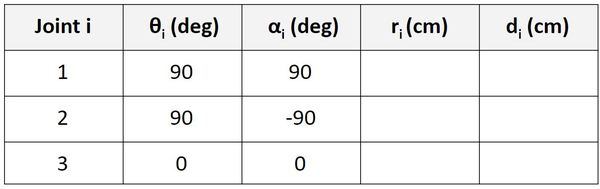
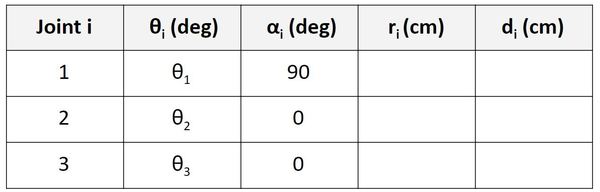
Let’s go to the Joint 3 row of the table.
α is the angle from z2 to z3 around x3. In the kinematic diagram, you can see that this angle is 0 degrees, so we put 0 in the table.
Find r
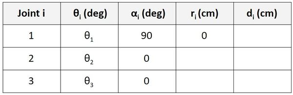
Let’s start with the Joint 1 row of the table.
r is the distance between the origin of frame 0 and the origin of frame 1 along the x1 direction. You can see in the diagram that this distance is 0.
Now let’s look at the Joint 2 row. r is the distance between the origin of frame 1 and the origin of frame 2 along the x2 direction. You can see in the diagram that this distance is 0.
Now let’s look at the Joint 3 row. r is the distance between the origin of frame 2 and the origin of frame 3 along the x3 direction. You can see in the diagram that this distance is 0.
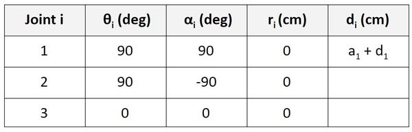
Find d
Now let’s find d. We’ll start on the first row of the table as usual.
d is the distance from x0 to x1 along the z0 direction. You can see that this distance is a1 + d1. a1 is the distance between the origin of frame 0 and the origin of frame 1 when the linear actuator (i.e. motor that generates linear motion) is in its home position, unextended. d1 is the distance the actuator extends beyond the home position.
Now let’s take a look at frame 1 to frame 2. d is the distance from x1 to x2 along the z1 direction. You can see that this distance is a2 + d2.
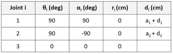
Now let’s take a look at frame 2 to frame 3. d is the distance from x2 to x3 along the z2 direction. You can see that this distance is a3 + d3.
To check your work, all of the link lengths and all of the joint variables in the kinematic diagram should appear in the Denavit-Hartenberg table.
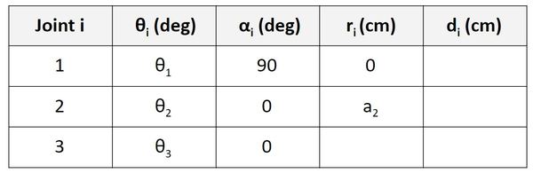
Example 2 – Articulated Robot
We have four reference frames, so we need to have three rows in our Denavit-Hartenberg parameter table.
Let’s begin by looking at the first column of the table.
Find θ
For the Joint 1 row (Servo 0), we are going to focus on the relationship between frame 0 and frame 1. θ is the angle from x0 to x1 around z0.
If you look at the diagram, take the thumb of your right hand and stick it in z0 direction. Your fingers curl in the direction of positive rotation. The angle from x0 to x1 around z0 is θ1 degrees in the counterclockwise (i.e. positive) direction.
Now, let’s look at the Joint 2 row. We take a look at the rotation between frame 1 and frame 2. θ is the angle from x1 to x2 around z1.
If you look at the diagram, take the thumb of your right hand and stick it in z1 direction. Your fingers curl in the direction of positive rotation. The angle from x1 to x2 around z1 is θ2 degrees in the counterclockwise (i.e. positive) direction.
Now, let’s look at the Joint 3 row. We take a look at the rotation between frame 2 and frame 3. θ is the angle from x2 to x3 around z2.
If you look at the diagram, x2 and x3 both point in the same direction. The axes are therefore aligned. When the robot is in motion, the angle from x2 to x3 around z2 will be θ3 degrees, so let’s put that in the third row of our table.
Find α
Let’s start with the Joint 1 row of the table.
α is the angle from z0 to z1 around x1.
Take your right thumb and point it in the x1 direction. Curl your fingers counterclockwise from z0 to z1. The angle is 90 degrees.
Let’s go to the Joint 2 row of the table.
α is the angle from z1 to z2 around x2. Take your right thumb, and stick it in the x2 direction. The angle between z1 and z2 is 0 degrees since both point in the same direction.
Let’s go to the Joint 3 row of the table.
α is the angle from z2 to z3 around x3. In the kinematic diagram, you can see that this angle is 0 degrees, so we put 0 in the table.
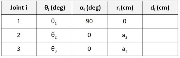
Find r
Let’s start with the Joint 1 row of the table.
r is the distance between the origin of frame 0 and the origin of frame 1 along the x1 direction. You can see in the diagram that this distance is 0.
Now let’s look at the Joint 2 row. r is the distance between the origin of frame 1 and the origin of frame 2 along the x2 direction. You can see in the diagram that this distance is a2.
Now let’s look at the Joint 3 row. r is the distance between the origin of frame 2 and the origin of frame 3 along the x3 direction. You can see in the diagram that this distance is a3.
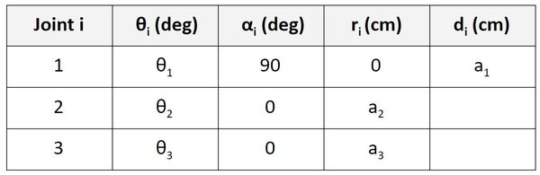
Find d
Now let’s find d. We’ll start on the first row of the table as usual.
d is the distance from x0 to x1 along the z0 direction. You can see that this distance is a1. a1 is the distance between the origin of frame 0 and the origin of frame 1. No matter how the servos move, this distance will always remain a1.
Now let’s take a look at frame 1 to frame 2. d is the distance from x1 to x2 along the z1 direction. You can see that this distance is 0.
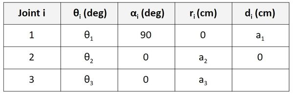
Now let’s take a look at frame 2 to frame 3. d is the distance from x2 to x3 along the z2 direction. You can see that this distance is 0.
To check your work, all of the link lengths and all of the joint variables in the kinematic diagram should appear in the Denavit-Hartenberg table.
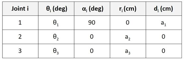
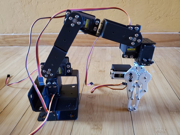
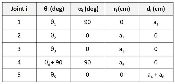
Example 3 – Six Degree of Freedom Robotic Arm
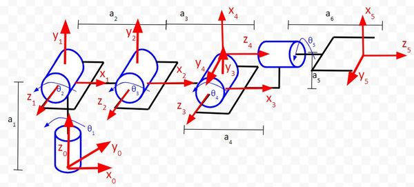
We have six reference frames, so we need to have five rows in our Denavit-Hartenberg parameter table.
See if you can do this one all by yourself, and then use the table below to check your work. Remember the rules:
- θ is the angle from xn-1 to xn around zn-1.
- α is the angle from zn-1 to zn around xn.
- r (sometimes you’ll see the letter ‘a’ instead of ‘r’) is the distance between the origin of the n-1 frame and the origin of the n frame along the xn direction.
- d is the distance from xn-1 to xn along the zn-1 direction.
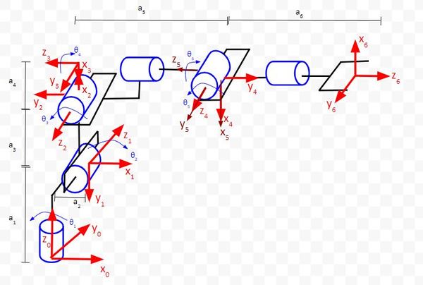
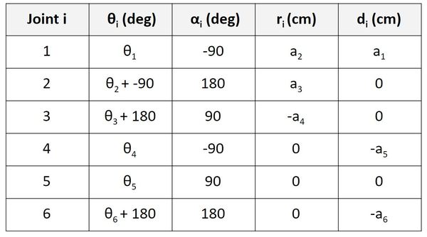
Example 4 – Six Degree of Freedom Collaborative Robot
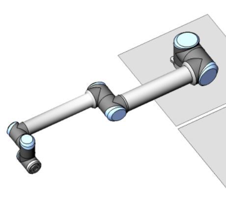
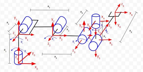
We have seven reference frames, so we need to have six rows in our Denavit-Hartenberg parameter table.
See if you can do this one all by yourself, and then use the table below to check your work. Remember the rules:
- θ is the angle from xn-1 to xn around zn-1.
- α is the angle from zn-1 to zn around xn.
- r (sometimes you’ll see the letter ‘a’ instead of ‘r’) is the distance between the origin of the n-1 frame and the origin of the n frame along the xn direction.
- d is the distance from xn-1 to xn along the zn-1 direction.
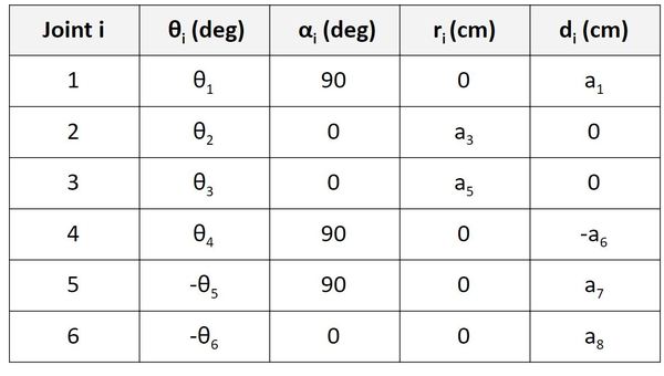
A few things to note:
- We have negative values for θ above due to the clockwise rotation about the zn-1 axis.
- I also didn’t use all of the a variables in the diagram because some of these measurements are irrelevant for calculating the Denavit-Hartenberg parameter table.
- Displacement is a vector quantity, which means it has both a magnitude and a direction. You’ll therefore see negative values for a in the table above.
Example 5 – Six Degree of Freedom Industrial Robot
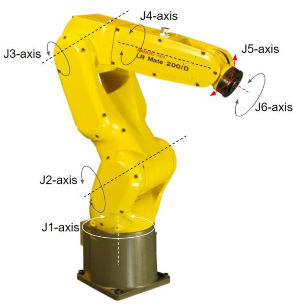
We have seven reference frames, so we need to have six rows in our Denavit-Hartenberg parameter table.
See if you can do this one all by yourself, and then use the table below to check your work. Remember the rules:
- θ is the angle from xn-1 to xn around zn-1.
- α is the angle from zn-1 to zn around xn.
- r (sometimes you’ll see the letter ‘a’ instead of ‘r’) is the distance between the origin of the n-1 frame and the origin of the n frame along the xn direction.
- d is the distance from xn-1 to xn along the zn-1 direction.
Remember when you’re trying to find theta that rotation in the counterclockwise direction (as viewed from looking down on the axis of rotation) is positive. Otherwise, it is negative.
You point your thumb in the direction of the axis of rotation and curl your fingers. Your finger-curl direction is positive rotation.
References
Credit to Professor Angela Sodemann from whom I learned these important robotics fundamentals. Dr. Sodemann teaches robotics over at her website, RoboGrok.com. While she uses the PSoC in her work, I use Arduino and Raspberry Pi since I’m more comfortable with these computing platforms. Angela is an excellent teacher and does a fantastic job explaining various robotics topics over on her YouTube channel.