How to Transmit Time and Temperature Using a TMP36 Sensor and Arduino

In this post, I’ll explain how to transmit time and temperature using a TMP36 sensor and an Arduino. The application that you will develop executes on an Arduino and transmits the time and temperature at a periodic rate of around 10 seconds across a Serial bus (e.g. USB) to a host computer (such as your personal laptop computer).

Requirements

Here are the requirements I created for this project:

  • The system must execute on an Arduino.
  • A temperature sensor connected to an Arduino must be calibrated.
  • The main program must use a Round Robin with interrupts design:
    • The temperature must be captured and converted to Fahrenheit.
    • The temperature must begin recording after the temperature has stabilized at room temperature.
    • The temperature must be recorded at a periodic rate of around 10 seconds (i.e. 10,000 milliseconds) at room temperature.
    • The temperature must then be recorded for 5 minutes at a periodic rate of around 10 seconds inside a refrigerator.
    • The temperature must then be recorded for 5 minutes at a periodic rate of around 10 seconds at room temperature.
  • The time and temperature must be transmitted across a Serial bus such as USB to my host.
  • The time and temperature data must be exported as a comma separated value file.
  • The comma separated value file must be read into a spreadsheet program (e.g. Microsoft Excel).
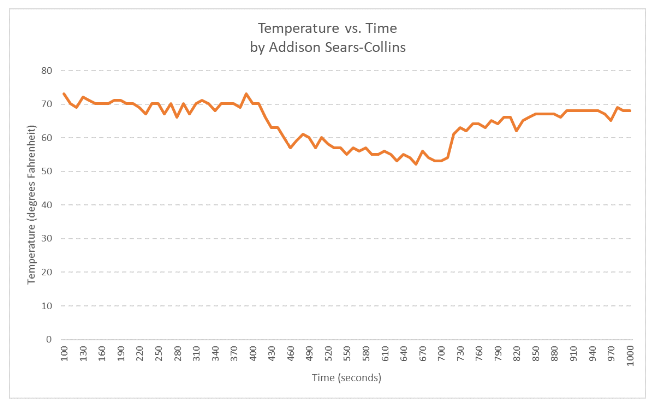
  • The temperature vs time must be plotted.

Hardware Design

The following components are used in this project. You will need:

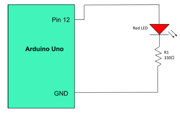
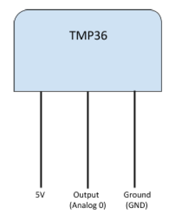
Here is the diagram of the TMP36 temperature sensor:

tmp36_sensor_diagram

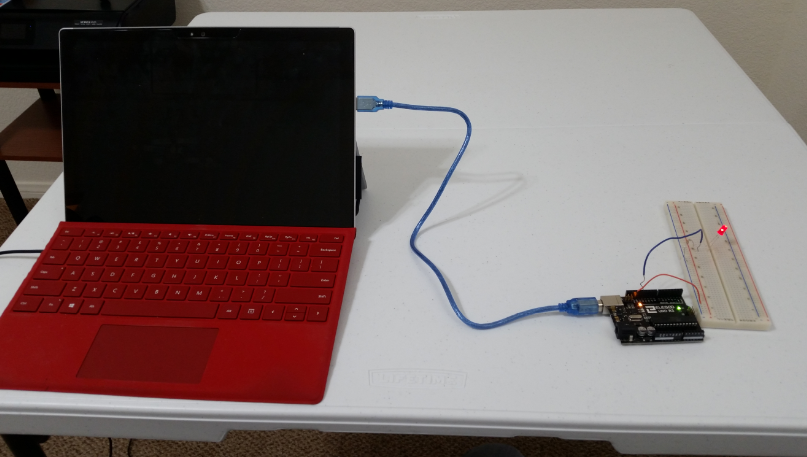
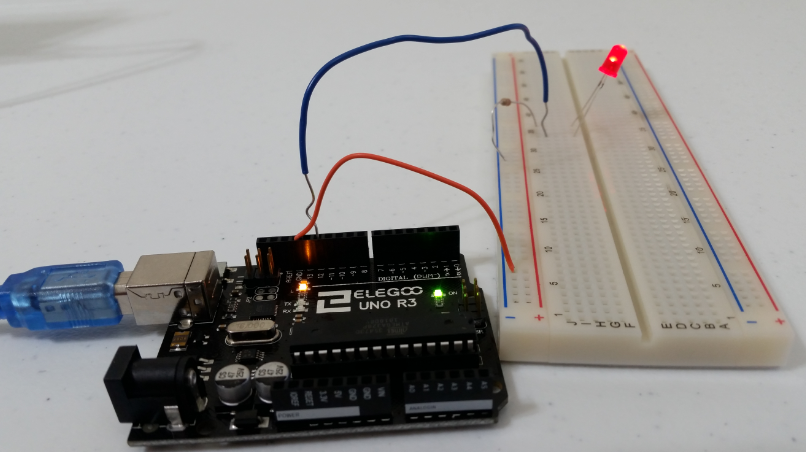
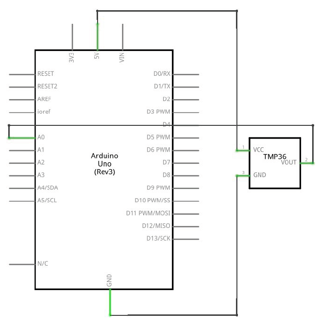
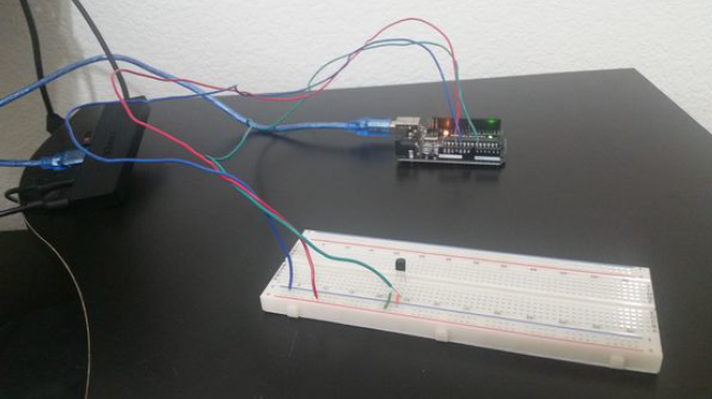
Here is the diagram of the hardware setup:

tmp36

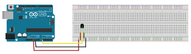
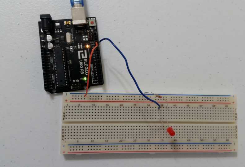
Here are the steps for setting up the hardware of the Serial Transmit of Temperature system:

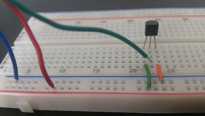
  • Step 1. Place the TMP36 sensor on the breadboard. Each lead of the sensor will be on a different rail section of the breadboard.
  • Step 2. Connect a jumper wire between the ground lead of the TMP36 sensor and the – rail of the breadboard.
  • Step 3. Connect a jumper wire between the – rail of the breadboard and the GND pin of the Arduino.
  • Step 4. Connect a jumper wire between the 5V pin of the Arduino and the + rail of the breadboard.
  • Step 5. Connect a jumper wire between + rail of the breadboard and the 5V lead of the TMP36 sensor.
  • Step 6. Connect a jumper wire between the middle output lead of the TMP36 sensor and the Analog 0 pin of the Arduino.
tmp36_sensor

Here are the steps for calibrating the TMP36 sensor:

We will use the One Point Calibration technique using a known temperature, 32°F, which is the freezing point of water.

  1. Crush several ice cubes and place in a plastic bag with some distilled water (Ada 2015).
  2. Close the bag up, making sure it is tied tight.
  3. Make sure the bag is completely dry on the outside and place it on top of the TMP36 sensor.
  4. Adjust temperature accordingly to calibrate.

Implementation

Here is the source code that you will need to load to your Arduino:

#include <TimerOne.h>
// This TimerOne.h library handles time-based interrupts

/**
 * In this program, we develop an application which executes on an Arduino 
 * and transmits the time and temperature at a periodic rate of around 10 
 * seconds across a Serial bus (USB) to the Host.
 * 
 * Uses the timer interrupts technique discussed on page 270 in 
 * "Exploring Arduino: Tools and Techniques for Engineering Wizardry" 
 * by Jeremy Blum
 * 
 * @version 7.0 2019-02-14
 * @author Addison Sears-Collins
 */
 
// Assign a name to the TMP36 sensor pin on the Arduino Uno
const unsigned int TEMP_SENSOR_PIN = A0;

// Flag used to stop the program
bool done = false;

// Used for capturing the time
unsigned long time;

// Used for capturing the temperature in Fahrenheit
float temp_fahrenheit;

/**
 *  Function runs only once, after each powerup or reset of the Arduino Uno
 */
void setup() {
  
  // Open the serial port and set the data transmission rate to 9600 bits 
  // per second. 9600 is the default baud rate for Arduino Uno.
  Serial.begin(9600); 
  
  // Show a welcome message as human-readable ASCII text
  Serial.println("SERIAL TRASMIT OF TEMPERATURE PROGRAM");
  Serial.println("This program transmits the time and temperature at a periodic");
  Serial.println("rate of ~10 seconds across a Serial bus (USB) to the Host.");
  Serial.println("Created by Addison Sears-Collins");
  Serial.println("");
  Serial.println("Press ! to end the program");
  Serial.println("");
  Serial.println("Recording temperature every 10 seconds...");
  Serial.println("");
  Serial.println("TIME, TEMPERATURE IN DEGREES FAHRENHEIT");

  // Interrupt: Set a timer of length 10000000 microseconds (10 seconds)
  Timer1.initialize(10000000);

  //Runs "isr_read_temperature" on each timer interrupt
  Timer1.attachInterrupt(isr_read_temperature); 
 
}

/**
 *  Main function
 */
void loop() {

  // Wait 100 seconds for temperature to stabilize
  // Temperature is being read in the background
  // via the interrupts
  delay(100000);

  while(!done) {    

    // Display the time and temperature
    display_time_and_temperature();
  
    // End program if sentinel is entered 
    end_program();    

    // Display time and temperature every 10 seconds
    delay(10000);
  }
  
  // Do nothing
  while (true) {}
}

/**
  * This function is the interrupt service routine.
  * It reads the voltage and converts to degrees Fahrenheit
  */
void isr_read_temperature() {
  
  // Read the voltage of the TMP36 sensor
  int sensor_voltage = analogRead(TEMP_SENSOR_PIN);
  
  // Calibrated. Equation taken from datasheet.
  // http://kookye.com/wp-content/uploads/samplecode/tempsensor.txt
  temp_fahrenheit = 5.1 + ((125 * sensor_voltage) >> 8);
}

/**
  * Function displays the time and temperature
  */
void display_time_and_temperature() {
  
  // Capture the time and covert to seconds
  time = millis() / 1000;

  // Display the time
  Serial.print(time); 
  Serial.print(" , ");
  // Println so the next line begins on a new line
  // Display the temperature in Fahrenheit
  Serial.println(temp_fahrenheit);   
}

/**
  * This function ends the program
  */
void end_program() {
  
  // Used for reading data from the serial monitor
  char ch;

  // Check to see if ! is available to be read
  if (Serial.available()) {     
  
    // Read the character
    // Serial.read() returns the first (oldest) character in the buffer 
    // and removes that byte of data from the buffer
    ch = Serial.read();    

    // End the program if an exclamation point is entered in the
    // serial monitor
    if (ch == '!') {
      done = true;  
      Serial.println("Finished recording temperature. Goodbye.");
    }
  }    
}

temperature_vs_time_tmp36_sensor
Graph of Temperature vs Time

Video

How to Display a String as Morse Code on an LED Using Arduino

In this post, I’ll show you how to develop an application which executes on an Arduino and displays a user typed string, such as “Hello World”, as Morse code on an LED.

Named after Samuel F.B. Morse, the inventor of the telegraph, Morse code is a character encoding scheme that represents letters as long and short pulses of sound or light.

Requirements

The system that is developed must satisfy the following requirements:

  • It must execute on an Arduino. The Arduino version used was version 1.8.8. Most Arduino versions will work.
  • It must display a user typed string, such as “Hello World”, as Morse code on an LED (or several LEDs), or an LCD.
    • A dash is three times as long as a dot.
    • The time between each dot or dash in the same letter is equal to the duration of one dot.
    • The time between two letters is the duration of one dash.
    • The time between two words is the same duration as seven dots.
  • It must use a Round Robin design where a loop:
    • Waits for a string
    • Displays the string in Morse code
    • Exits the loop only if a sentinel is entered (e.g. !)

Hardware Design

The following components are used for the Morse code LED system. You will need:

Here is the schematic:

Software Design

Here are the steps for the Morse code LED system:

  • Step 1. Prompt the user to enter a message on the Serial Monitor. The input for the message contains characters (letters and/or numbers).
  • Step 2. Read each character, one at a time.
  • Step 3. Convert each character into the equivalent Morse Code.
  • Step 4. Convert each Morse code sequence into the corresponding sequence of dots and dashes.
  • Step 5. Transmit the dots and dashes to the LED while transmitting the message to the Serial Monitor.
  • Step 6. Exit the loop if user enters the sentinel value of “!”

Implementation

Here is the source code that you will need to load to your Arduino:

/**
 * In this program, we develop an application which executes on an Arduino 
 * Uno and displays a user typed string, such as “Hello World”, as Morse 
 * code on an LED.   
 * 
 * @version 1.0 2019-01-31
 * @author Addison Sears-Collins
 */
 
// Assign a name to the digital pin 12
unsigned int led_pin = 12;

// Declare an array named letters that holds addresses of string literals 
// (i.e. an array of pointers to strings composed of dots and dashes) 
// Done to preserve memory because strings are not equal in size. A 2D array
// would be a waste of space.
char *letters[] = {
  // The letters A-Z in Morse code  
  ".-", "-...", "-.-.", "-..", ".", "..-.", "--.", "....", "..",    
  ".---", "-.-", ".-..", "--", "-.", "---", ".--.", "--.-", ".-.",  
  "...", "-", "..-", "...-", ".--", "-..-", "-.--", "--.."          
};

char *numbers[] = {
  // The numbers 0-9 in Morse code  
  "-----", ".----", "..---", "...--", "....-", ".....", "-....", 
  "--...", "---..", "----."
};

unsigned int dot_duration = 200;
bool done = false;

/**
 *  Function runs only once, after each powerup or reset of the Arduino
 */
void setup() {
  // Set the LED to output
  pinMode(led_pin, OUTPUT);
  
  // Open the serial port and set the data transmission rate to 9600 bits 
  // per second. 9600 is the default baud rate for Arduino.
  Serial.begin(9600); 
  
  // Show welcome message as human-readable ASCII text
  Serial.println("MORSE CODE LED PROGRAM");
  Serial.println("This program translates your message into Morse code");
  Serial.println("and flashes it on an LED.");
  Serial.println("Author: Addison Sears-Collins");
  Serial.println("");
  Serial.println("Enter your message(s) or ! to exit: ");
}

/**
 *  Main function that drives the system
 */
void loop() {
  char ch;
  
  // This loop waits for a string, displays it in Morse code, and only exits 
  // the loop if the sentinel is entered. 
  while (!done) {
  
    // Check to see if there are letters or numbers available to be read
    if (Serial.available()) {     
  
      // Read one letter or number at a time
      // Serial.read() returns the first (oldest) character in the buffer 
      // and removes that byte of data from the buffer
      ch = Serial.read();    
  
      // Check for uppercase letters
      if (ch >= 'A' && ch <= 'Z') {
        Serial.println(ch);
        flash_morse_code(letters[ch - 'A']);        
      }
      // Check for lowercase letters
      else  if (ch >= 'a' && ch <= 'z') {
        Serial.println(ch);
        flash_morse_code(letters[ch - 'a']);
      }
      // Check for numbers
      else if (ch >= '0' && ch <= '9') {
        Serial.println(ch);
        flash_morse_code(numbers[ch - '0']);
      }
      // Check for space between words
      else if (ch == ' ') {
      
        // Put space between two words in a message...equal to seven dots
        delay(dot_duration * 7);       
      }
      // Check for sentinel value
      else if (ch == '!') {
        done = true;  
        Serial.println("Thank you! Your messages were sent successfully.");
        Serial.println("Goodbye.");
      }
    }     
  }  
  // Do nothing
  while(true) {}
}

/**
  *  Flashes the Morse code for the input letter or number
  *  @param morse_code pointer to the morse code
  */
void flash_morse_code(char *morse_code) {
   
  unsigned int i = 0;
   
  // Read the dots and dashes and flash accordingly
  while (morse_code[i] != NULL) {
    flash_dot_or_dash(morse_code[i]);
    i++;
  }
   
  // Space between two letters is equal to three dots
  delay(dot_duration * 3);    
}

/**
  *  Flashes the dot or dash in the Morse code
  *  @param dot_or_dash character that is a dot or a dash
  */
void flash_dot_or_dash(char dot_or_dash) {
  
  // Make the LED shine
  digitalWrite(led_pin, HIGH);
  
  if (dot_or_dash == '.') { // If it is a dot
    delay(dot_duration);           
  }
  else { // Has to be a dash...equal to three dots
    delay(dot_duration * 3);           
  }
  
  // Turn the LED off
  digitalWrite(led_pin, LOW);

  // Give space between parts of the same letter...equal to one dot
  delay(dot_duration); 
}

Video

Setting up the BNO055 Absolute Orientation Sensor

Video Transcript

In this video, we’ll set up the Adafruit BNO055 Absolute Orientation Sensor from scratch, step-by-step.

The BNO055 is actually three sensors in one device. It includes an accelerometer to measure acceleration forces, a gyroscope that uses Earth’s gravity to help determine orientation, and a magnetometer that measures magnetism. Typical applications of this sensor include navigation, robotics, fitness, augmented reality, and tablet computers.

By the end of this video, you will have all of the hardware and software of the BNO055 sensor set up and ready to go so you can measure the roll, pitch, and yaw of an aerial electronic device, such as a drone.

Ok, let’s get started. Feel free to pause the video at any time as you follow along with me.

You will need:

To begin, get your BNO055 IMU board, the header strip, and the solderless breadboard. Lay them out on a table.

Prepare the header strip by cutting it to an appropriate length and placing it into the breadboard. You want a piece with 4 pins and a piece with 6 pins so that they can fit into the holes on the BNO055 board.
Place the long pins down into the solderless breadboard.

Next place the BNO055 board on top of the pins.

We will now solder all of the pins to the BNO055 in order to solidify electrical contact:

  • Gather all the materials presented earlier in the video, and lay them out on a table.
  • If you have safety glasses and latex gloves, put them on. Eyeglasses are fine.
  • Turn on the USB fan for ventilation, in order to avoid breathing in the soldering smoke.
  • Turn on the soldering iron to the 4 heat setting.
  • Lay your damp sponge in the center of the silicon mat.
  • Once the iron is hot, tin the tip by adding a little bit of solder to cover the tip.
  • Now wipe the tip off on the damp sponge to remove all but a thin layer of solder to help the tip last longer and to facilitate the transfer of heat from the soldering iron to the joint.
  • Place the tip of the soldering iron to the joint, where the header pin and board meet, to heat it up.
  • Feed a small amount of solder to the joint and remove the soldering iron after 2 seconds in order to not damage the board. Do this for all the pins in the BNO055.
  • OK, we are done soldering. With the soldering iron hot, wipe it off on a damp sponge.
  • Turn off the soldering iron and clean everything up.

With the BNO055 all cooled off, we need to wire the BNO055 to the Arduino Uno using the solderless breadboard. Here are the connections we need to make.

  • Connect Vin of the BNO055 to the power supply of 5V on the Arduino
  • Connect GND of the BNO055 to GND on the Arduino
  • Connect the SDA pin of the BNO055 to the SDA pin of the Arduino, which is A4.
  • Connect the SCL pin of the BNO055 to the SCL pin of the Arduino, which is A5.

Next, we attach the Arduino Uno to the USB port on our main desktop computer.

Now, on our desktop computer, we open Arduino.

We navigate to the Library manager and install two libraries:

  1. The Adafruit Unified Sensor system library to retrieve orientation data in a standard data format, and…
  2. The Adafruit_BNO055 driver, which supports reading raw sensor data.

Now, go to File -> Examples -> Adafruit BNO055, and click sensorapi. The Arduino sketch that pops up is a demo that will help us test the BNO055.

First double check the Arduino is properly connected to your desktop computer by going to Tools -> Port. Make sure the Arduino/Genuino Uno has a checkmark next to it.

Now, let’s run the demo. Save the sensorapi sketch, compile it by clicking the checkmark, and upload it to the Arduino by clicking the right arrow button.

Once it is finished uploading, open the Serial monitor by clicking the magnifying glass in the upper right corner. We see the x, y, and z orientation data flowing in real-time.

However, we want Roll, Pitch, Yaw data and not X, Y, Z. So we need to change X, Y, and Z to Roll, Pitch, Yaw.

I’m going to use this website to refresh myself what roll, pitch, and yaw are.

Yaw is movement from side to side. Like when you shake your head “no.”

Pitch is movement up and down. Like when you nod your head “yes.”

Roll is movement from left to right. Like when you tilt your head from side to side.

Ok, let’s start the sensorapi program up again and see what happens to the X, Y, and Z values when we move the BNO055 board around, in different orientations. The front of the BNO055 board is labeled BNO055. 

We rotate the BNO055 board around to 90 degrees yaw in the East direction. I see the X value changes. Then we roll the board to the right. The Z value changes. I then pitch the board by pointing the board straight up at the sky. The Y value changes.  So there we have it. Yaw is X, Roll is Z, and Pitch is Y.

We go to the sensorapi code and modify it accordingly so that we use the terms Yaw, Roll, and Pitch, instead of X, Z, and Y, respectively.

Let’s compile and upload the program again to make sure everything is working properly. Here is the output of the Serial monitor.

Ok. That completes this video. You are now ready to use your BNO055.