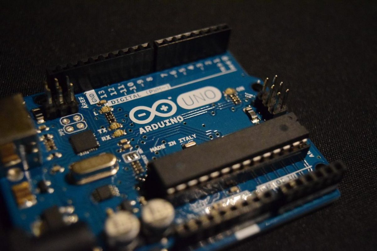
How do we connect ROS to an actual embedded system that operates in the real, physical world? I’ll show you how to do this now using Arduino.
Arduino is a popular microcontroller for building electronics projects. A microcontroller is a bunch of circuits that do stuff, such as accepting data input, doing calculations, and producing output. With respect to robotics development, Arduino would be the “brain” of a robot.
Fortunately, ROS can integrate with Arduino. We will install some software that will enable your Arduino to be a bonafide ROS node that can do everything a normal node can do, such as publish and subscribe to ROS messages.
Here are the official steps for interfacing Arudino with ROS, but I’ll walk you through the process below.
Table of Contents
- How to Install Arduino on Ubuntu Linux
- How to Blink an LED (Light-Emitting Diode) Using ROS and Arduino
Directions
How to Install Arduino on Ubuntu Linux
First, let’s download the Arduino IDE (Linux 64 bit version) to our computer. I will follow these instructions for installing the Arduino IDE on Ubuntu. Go to this website, and download the software:
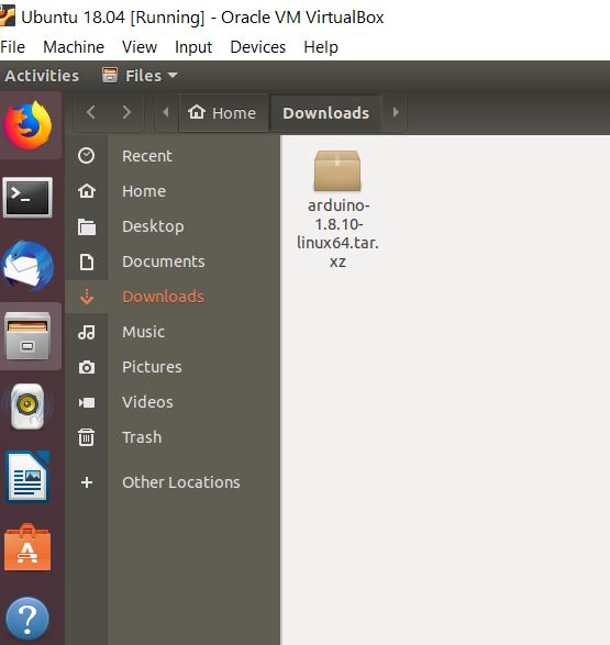
Save the file. It will be saved as tar.xz format to your Downloads folder.
Open a new terminal window.
Move to the Downloads folder (or wherever you saved the tar.xz file).
cd Downloads
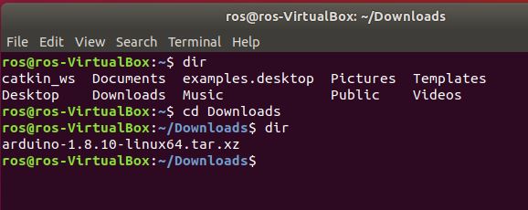
Run this command to extract the files (substitute FILENAME with the name of the file you just downloaded):
tar xvf <FILENAME>
In my case, I will run:
tar xvf arduino-1.8.10-linux64.tar.xz
You will see a bunch of file names print out to your screen.
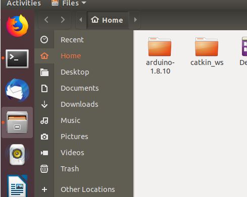
If you type the dir command, you will see the new folder. Let’s move that folder to the home directory. You can cut and paste it into the home directory using the file manager (the file cabinet on the left of the screen. Go there, then go to the Downloads folder, cut the file and paste it into the Home directory.

Now open up a new terminal window and type:
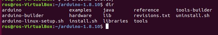
cd arduino-1.8.10
Type dir to see what files are inside.
To install the IDE, type:
sudo ./install.sh
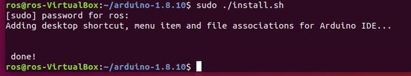
Here is the output. You should see a “done” message. A desktop icon will also be present. You can activate it by clicking on it and allowing permissions at the prompt.
Now, get your Arduino and connect it to the USB port on your computer.
Start Arduino by going into a new terminal window and typing:
arduino
You might see an error message like this:
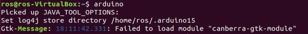
Failed to load module “canberra-gtk-module” … but already installed
To resolve that error, press CTRL+C and close the terminal window.
Open a new terminal window, and type:
sudo apt-get install libcanberra-gtk-module
Now open a new terminal window, and type:
arduino
Let’s see if everything works by trying to blink the light-emitting diode (LED) on your computer.
Go to File – > Examples -> 01.Basics, and choose Blink.
Try to upload that code to your Arduino by clicking the right arrow on the upper left of your screen.
You should see an error about the “Serial port not selected”.
Close out of your Ubuntu Virtual Machine completely. Do not save the state.
Set Up the Serial Port for VirtualBox With Ubuntu
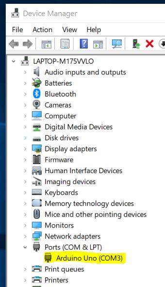
Assuming you are using Windows, go to your Device Manager. Search for that in your computer in the bottom left of your desktop.
Under Device Manager, you should see Ports (COM & LPT). Note that Arduino is port 3 (Make sure your Arduino board is connected to the USB port of your computer).
Open your VirtualBox.
Click Settings and go down to Serial Ports.
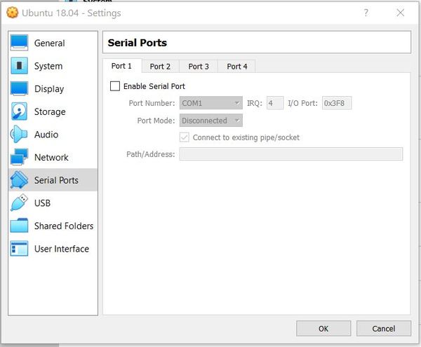
Make sure your settings look exactly like this:
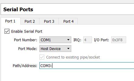
Note that the little box next to “Enable Serial Port” is checked.
Side Note: Any time you unplug your Arduino….say perhaps after using it within Ubuntu Linux or if you shutdown your PC….be sure to disable the “Enable Serial Port” option before restarting Ubuntu Linux in your Virtual Box. Otherwise, your Ubuntu Linux session will NOT launch. I’ve made this mistake numerous times, and it is frustrating.
After you are done, click OK.
Restart the VirtualBox with Ubuntu.
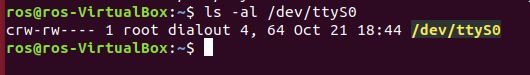
Open a new terminal window and type:
ls -al /dev/ttyS0
Here is the output:
Now we need to give the IDE permissions to access the device.
In a new terminal window, find out your username. Type:
whoami
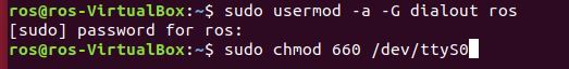
Now type the following commands, replacing YOUR_USER_NAME with what you found above:
sudo usermod -a -G dialout YOUR_USER_NAME
sudo chmod 660 /dev/ttyS0
Reboot your machine:
sudo reboot
Open up a terminal window and launch Arduino by typing:
arduino
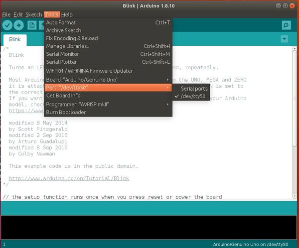
Go to Tools -> Port, and you should see /dev/ttyS0. This is your Arduino board that is connected to the USB port of your computer. Make sure /dev/ttyS0 is checked.
Now open the Blink sketch again. Go to File – > Examples -> 01.Basics, and choose Blink.
Click the Upload button…the right arrow in the upper left of your screen.
The LED on your Arduino should be blinking! If it is not, go back to the beginning of this tutorial and follow the steps carefully.
To turn off the blinking light, open up a new sketch and upload it to your board. Go to File -> New.
Integrate Arduino With ROS
Now that we know Arduino is working, we need to integrate it with ROS. Here are the official instructions. I’ll walk you through the steps below.
Let’s install the necessary packages.
Close Arduino. Then type the following commands in a new terminal window (these will take a while to download so be patient):
sudo apt-get install ros-melodic-rosserial-arduino
sudo apt-get install ros-melodic-rosserial
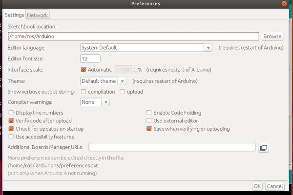
Open the IDE by typing arduino and go to File -> Preferences. Make a note of the Sketchbook location. Mine is:
/home/ros/Arduino
Open a new terminal window and go to the sketchbook location you noted above. I’ll type:
cd Arduino
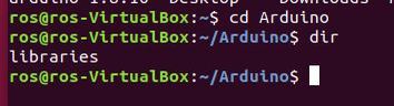
Type the dir command to see the list of folders.
Go to the libraries directory.
cd libraries
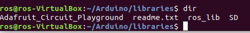
Within that directory, run the following command to build the Arduino library that will be used by ROS (don’t leave out that period that comes at the end of the command):
rosrun rosserial_arduino make_libraries.py .
Type the dir command to see the list of folders. You should now see the ros_lib library.
Make sure the Arduino IDE is closed. Now open it again.
You should see some sample code. Now, let’s take a look at the Blink example.
Go to File -> Examples -> ros_lib
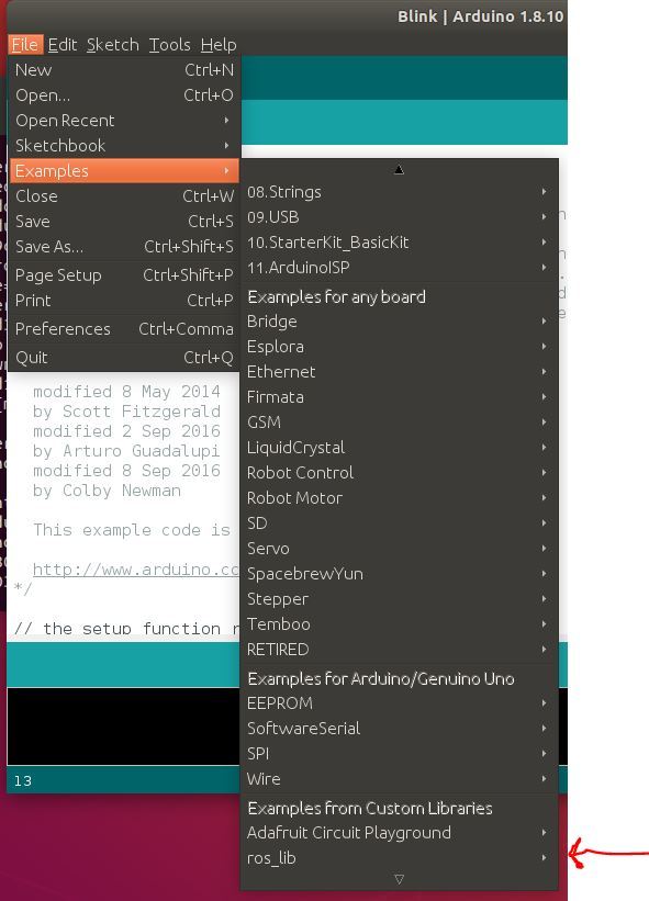
How to Blink an LED (Light-Emitting Diode) Using ROS and Arduino
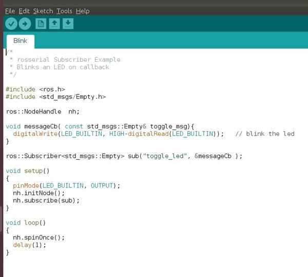
The Blink example is analogous to a “Hello World” program. Blinking an LED is the most basic thing we can do to make sure the hardware is working properly and that it accepts the software we are developing on our laptop. The goal of the Blink example is to toggle an LED on and off.
In this example, Arduino is going to be considered a Subscriber node. It will subscribe to a topic called toggle_led. Publishing a message to that topic causes the LED to turn on. Publishing a message to the topic again causes the LED to turn off.
Go to File -> Examples -> ros_lib and open the Blink sketch.
Now we need to upload the code to Arduino. Make sure your Arduino is plugged into the USB port on your computer.
Upload the code to your Arduino using the right arrow button in the upper left of your screen. When you upload the code, your Arduino should flicker a little bit.
Open a new terminal window and type:
roscore
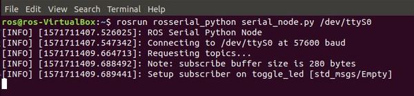
In a new terminal window, launch the ROS serial server. This command is explained here on the ROS website. It is necessary to complete the integration between ROS and Arduino:
rosrun rosserial_python serial_node.py /dev/ttyS0
Now let’s turn on the LED by publishing a single empty message to the /toggle_led topic. Open a new terminal window and type:
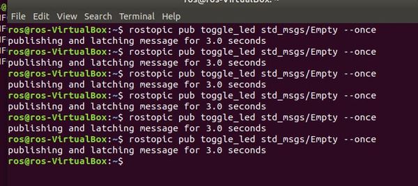
rostopic pub toggle_led std_msgs/Empty --once
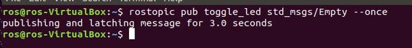
The LED on the Arduino should turn on. Note the yellow light is on (my Arduino is inside a protective case).
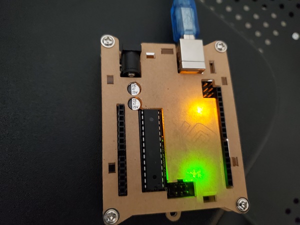
Now press the Up arrow in the terminal and press ENTER to run this code again. You should see the LED turn off. You might also see a tiny yellow light blinking as well. Just ignore that one…you’re interested in the big yellow light that you’re able to turn off and on by publishing single messages to the /toggle_led topic.

That’s it! You have now seen how you can integrate Arduino with ROS. To turn off your Arduino, all you need to do is disconnect it.