In this ROS 2 Navigation Stack tutorial, we will use information obtained from LIDAR scans to build a map of the environment and to localize on the map. The purpose of doing this is to enable our robot to navigate autonomously through both known and unknown environments (i.e. SLAM).
As noted in the official documentation, the two most commonly used packages for localization are the nav2_amcl package and the slam_toolbox. Both of these packages publish the map -> odom coordinate transformation which is necessary for a robot to localize on a map.
This tutorial is the fifth tutorial in my Ultimate Guide to the ROS 2 Navigation Stack (also known as Nav2).
You can get the entire code for this project here if you are using ROS Foxy.
If you are using ROS Galactic or newer, you can get the code here.
Let’s get started!
Prerequisites
You have completed the first four tutorials of this series:
- How to Create a Simulated Mobile Robot in ROS 2 Using URDF
- Set Up the Odometry for a Simulated Mobile Robot in ROS 2
- Sensor Fusion Using the Robot Localization Package – ROS 2
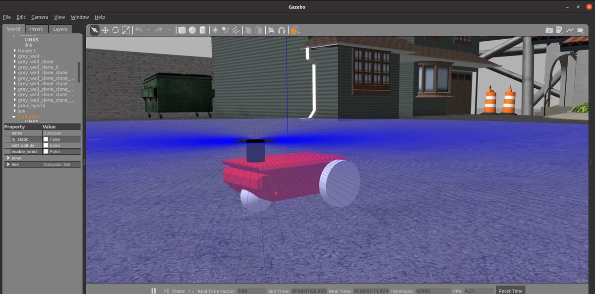
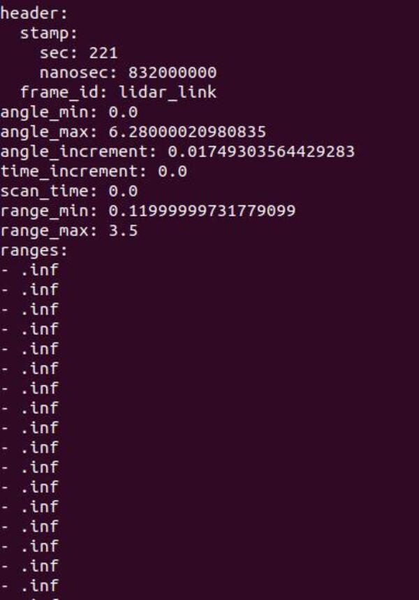
- Set Up LIDAR for a Simulated Mobile Robot in ROS 2
Create a Launch File
Open a new terminal window, and move to your launch folder.
colcon_cd basic_mobile_robot
cd launch
gedit basic_mobile_bot_v5.launch.py
Copy and paste this code into the file.
Save the file, and close it.
Add a Static Map
We now need to add a static map of our world so our robot can plan an obstacle-free path between two points.
I already created a map of the world in a previous tutorial, so we’ll use the yaml and pgm file from that tutorial.
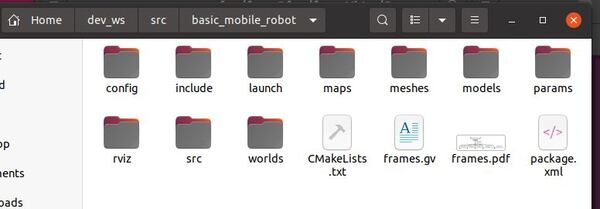
Go to your ~/dev_ws/src/basic_mobile_robot/maps folder.
Place this pgm file and this yaml file inside the folder.
Add Navigation Stack Parameters
Let’s add parameters for the ROS 2 Navigation Stack. The official Configuration Guide has a full breakdown of all the tunable parameters. The parameters enable you to do all sorts of things with the ROS 2 Navigation Stack.
The most important parameters are for the Costmap 2D package. You can learn about this package here and here.
A costmap is a map made up of numerous grid cells. Each grid cell has a “cost”. The cost represents the difficulty a robot would have trying to move through that cell.
For example, a cell containing an obstacle would have a high cost. A cell that has no obstacle in it would have a low cost.
The ROS Navigation Stack uses two costmaps to store information about obstacles in the world.
- Global costmap: This costmap is used to generate long term plans over the entire environment….for example, to calculate the shortest path from point A to point B on a map.
- Local costmap: This costmap is used to generate short term plans over the environment….for example, to avoid obstacles.
We will use the AMCL (Adaptive Monte Carlo Localization) algorithm for localizing the robot in the world and for publishing the coordinate transform from the map to odom frame.
AMCL localizes the robot in the world using LIDAR scans. It does this by matching real-time scan information to a known map. You can read more about AMCL here and here.
Go to your ~/dev_ws/src/basic_mobile_robot/params folder.
Place this nav2_params.yaml file inside the folder.
If you are using ROS 2 Galactic or newer, your code is here.
Create an RViz Configuration File
Go to your rviz folder.
colcon_cd basic_mobile_robot
cd rviz
Create a new RViz file.
gedit nav2_config.rviz
Copy and paste this code inside the file.
Save the file, and close it.
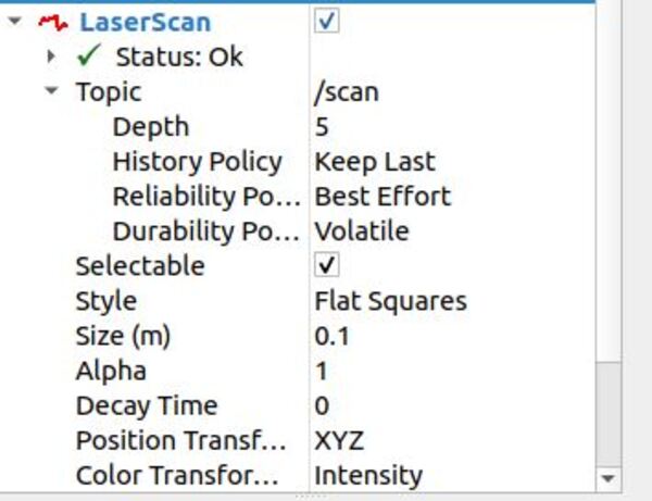
Update the Plugin Parameters
I updated the LIDAR plugin parameters inside model.sdf inside the basic_mobile_robot_description folder.
I also updated the differential drive plugin to use odometry data from the WORLD as the source rather than ENCODER.
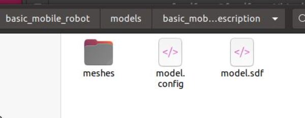
cd ~/dev_ws/src/basic_mobile_robot/models/basic_mobile_bot_description
gedit model.sdf
Make sure you copy and paste this code into the model.sdf file, and then save and close it.
Update the Robot Localization Parameters
Inside my ekf.yaml file, I updated the map_frame since we will be using a map. The robot_localization package will not be using the map, but I still want to update this parameter so that it is there if I need it.
cd ~/dev_ws/src/basic_mobile_robot/config
gedit ekf.yaml
Make sure you copy and paste this code into the ekf.yaml file, and then save and close it.
Build the Package
Now build the package by opening a terminal window, and typing the following command:
cd ~/dev_ws
colcon build
Launch the Robot Without SLAM
Open a new terminal window, and type the following command.
colcon_cd basic_mobile_robot
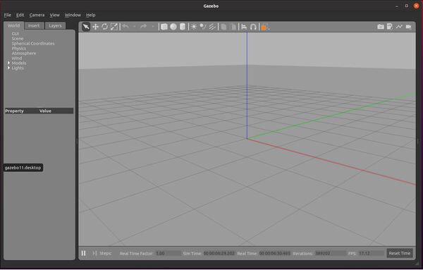
Launch the robot.
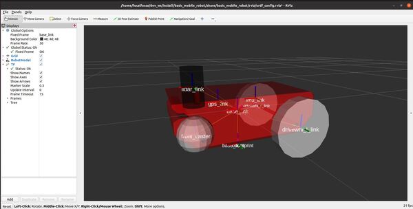
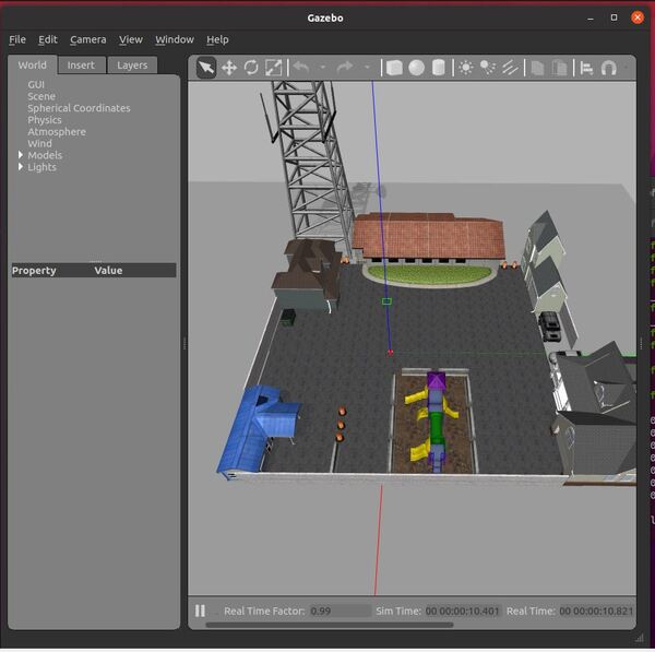
ros2 launch basic_mobile_robot basic_mobile_bot_v5.launch.py
Move the Robot From Point A to Point B
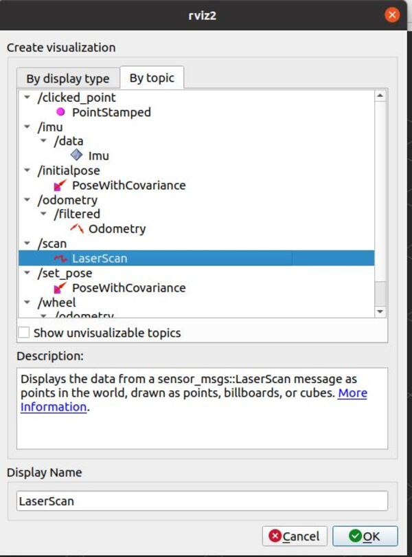
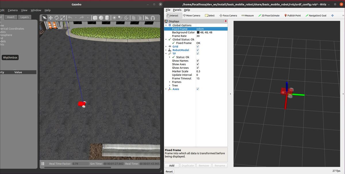
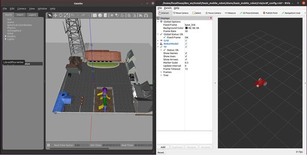
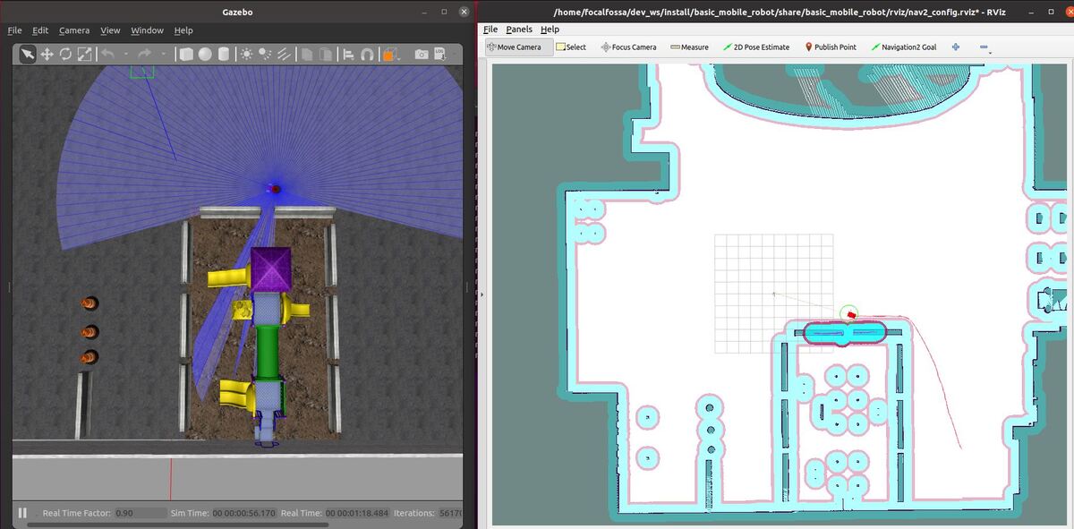
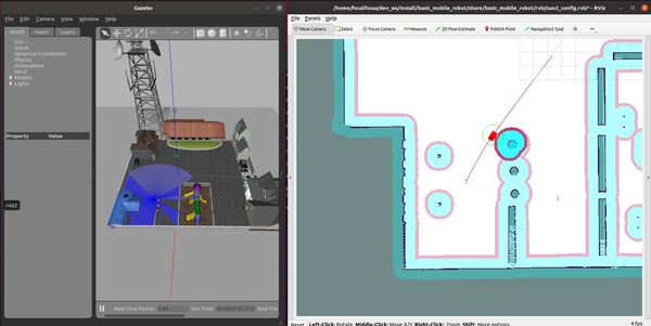
Now go to the RViz screen.
Set the initial pose of the robot by clicking the “2D Pose Estimate” on top of the rviz2 screen (Note: we could have also set the set_initial_pose and initial_pose parameters in the nav2_params.yaml file to True in order to automatically set an initial pose.)
Then click on the map in the estimated position where the robot is in Gazebo.
Set a goal for the robot to move to. Click “Navigation2 Goal” button in RViz, and click on a desired destination.
You can also request goals through the terminal by using the following command:
ros2 topic pub /goal_pose geometry_msgs/PoseStamped "{header: {stamp: {sec: 0}, frame_id: 'map'}, pose: {position: {x: 5.0, y: -2.0, z: 0.0}, orientation: {w: 1.0}}}"
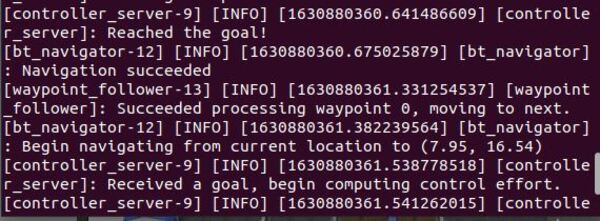
You will notice that we published the goal to the /goal_pose topic.
The wheeled robot will move to the goal destination.
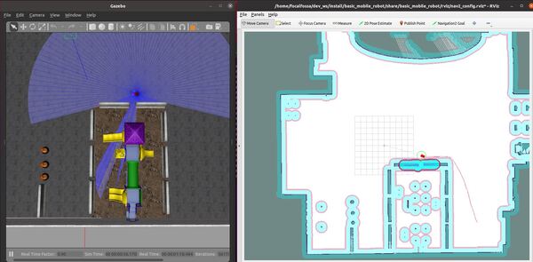
In the bottom left of the screen, you can Pause and Reset.
If the robot does not move at all, press CTRL+C in all windows to close everything down. Then try launching the robot again.
The key to getting good performance with the ROS 2 Navigation Stack is to spend a lot of time (it can take me several days) tweaking the parameters in the nav2_params.yaml file we built earlier. Yes, it is super frustrating, but this is the only way to get navigation to work properly.
Common things you can try changing are the robot_radius and the inflaition_radius parameters. You can also try changing the expected_planner_frequency, update_frequency, publish_frequency, and width/height of the rolling window in the local_costmap.
Also, you can try modifying the update_rate in the LIDAR sensor inside your robot model.sdf file.
Don’t change too many things all at once. Just change something, build the package, and then launch the robot again to see what happens. Then change another thing, and watch what happens, etc.
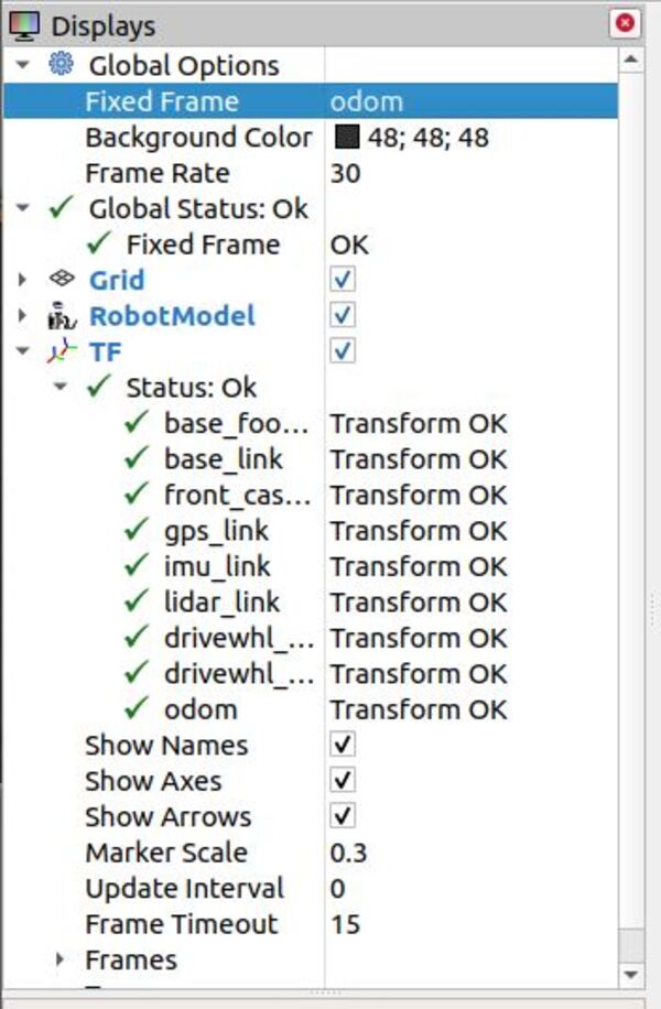
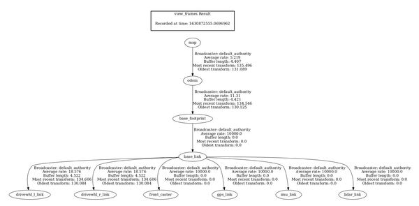
Now let’s check out the coordinate frames. Open a new terminal window, and type:
ros2 run tf2_tools view_frames.py
If you are using ROS 2 Galactic or newer, type:
ros2 run tf2_tools view_frames
In the current working directory, you will have a file called frames.pdf. Open that file.
evince frames.pdf
Here is what my coordinate transform (i.e. tf) tree looks like:
To see an image of the architecture of our ROS system, open a new terminal window, and type the following command:
rqt_graph
Press CTRL + C on all terminal windows to close down the programs.
Move the Robot Through Waypoints
Open a new terminal window, and type the following command.
colcon_cd basic_mobile_robot
Launch the robot.
ros2 launch basic_mobile_robot basic_mobile_bot_v5.launch.py
Now go to the RViz screen.
Set the initial pose of the robot by clicking the “2D Pose Estimate” on top of the rviz2 screen.
Then click on the map in the estimated position where the robot is in Gazebo.
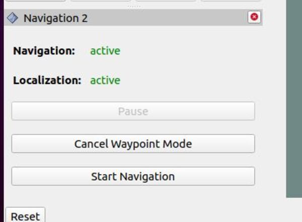
Now click the Waypoint mode button in the bottom left corner of RViz. Clicking this button puts the system in waypoint follower mode.
Click “Navigation2 Goal” button, and click on areas of the map where you would like your robot to go (i.e. select your waypoints). Select as many waypoints as you want.
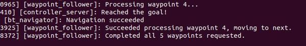
I chose five waypoints. Each waypoint is labeled wp_#, where # is the number of the waypoint.
When you’re ready for the robot to follow the waypoints, click the Start Navigation button.
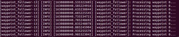
You should see your robot autonomously navigate to all the waypoints. At each waypoint, your robot will stop for 10-20 seconds, and then it will move to the next waypoint.

If your robot does not navigate to the waypoints, relaunch the robot and try again. Try selecting different waypoints.
The ROS 2 Navigation Stack waypoint follower functionality isn’t perfect. Many times, the robot will skip over waypoints or abandon them completely. The most common error I get when this happens is the following:
[bt_navigator]: Action server failed while executing action callback: “send_goal failed”
[bt_navigator]: [navigate_to_pose] [ActionServer] Aborting handle.
This issue is a known problem in ROS 2 Foxy, and it appears to be fixed in the latest version of ROS 2 (i.e. Galactic). We won’t upgrade ROS right now, but this is something to keep in mind if you are using a version of ROS 2 that is newer than ROS 2 Foxy.
In addition, I like to play around with the parameters in the nav2_params.yaml file located inside the params folder of your package. A complete guide to all the parameters is here.
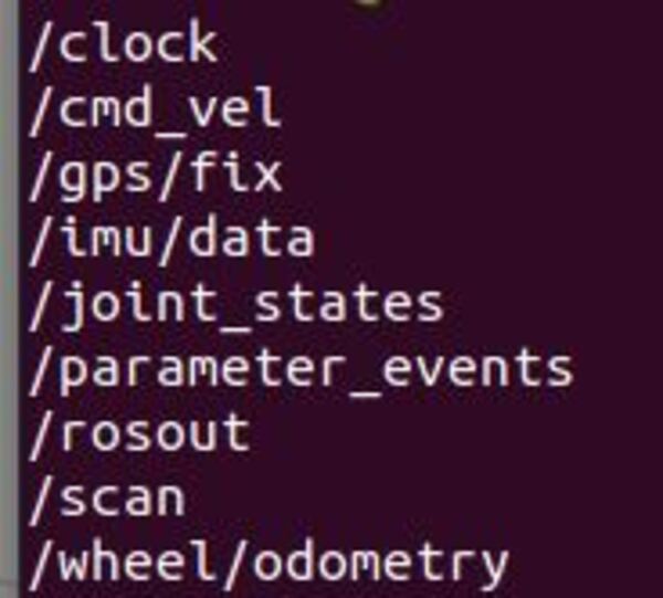
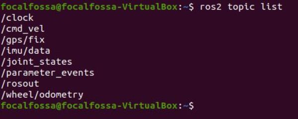
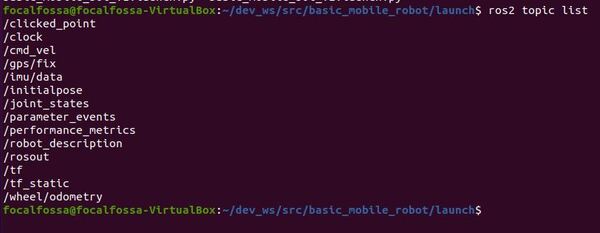
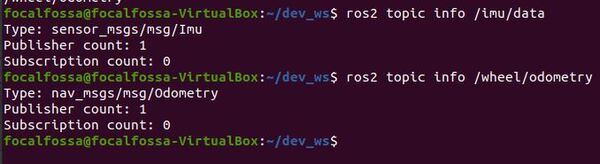
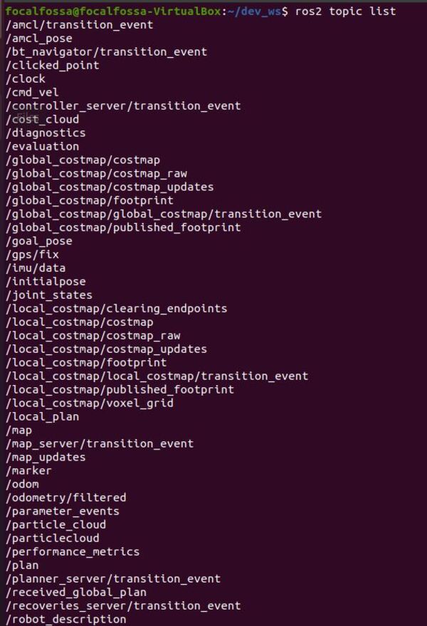
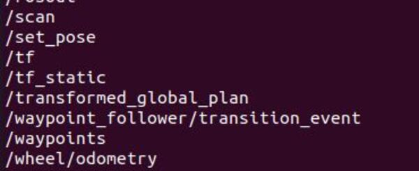
Finally, let’s check out the active ROS 2 topics.
ros2 topic list
Launch the Robot With SLAM
Make sure the SLAM toolbox is installed. Open a terminal window, and type:
sudo apt install ros-foxy-slam-toolbox
The syntax is:
sudo apt install ros-<ros2-distro>-slam-toolbox
Open the model.sdf file inside the basic_mobile_robot/models/basic_mobile_bot_description folder, and change the number of LIDAR samples (inside the <samples></samples> tag) to some high number like 120.
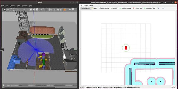
To launch the robot with SLAM (simultaneous localization and mapping), open a terminal window, and run the following command:
ros2 launch basic_mobile_robot basic_mobile_bot_v5.launch.py slam:=True
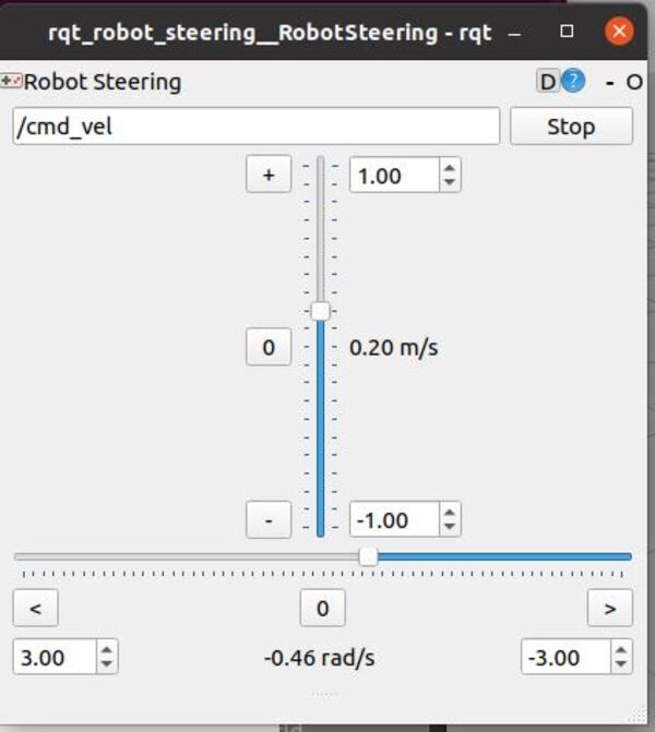
Use the rqt_robot_steering tool to slowly drive the robot around the room. Open a terminal window, and type:
rqt_robot_steering
If you are using ROS 2 Galactic or newer, type:
sudo apt-get install ros-galactic-rqt-robot-steering
Where the syntax is:
sudo apt-get install ros-<ros-distribution>-rqt-robot-steering
Then type:
ros2 run rqt_robot_steering rqt_robot_steering --force-discover
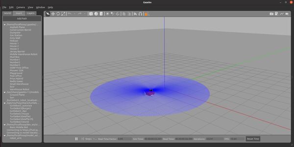
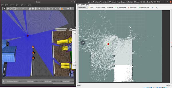
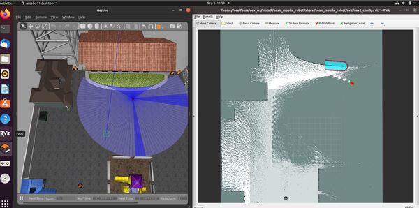
The robot will build a map and localize at the same time. You can also use autonomous navigation using the RViz buttons like we did in the last section.
Save the Map (ROS Foxy and Older)
If you are using a ROS Distribution that is ROS Foxy and older, you will have to follow these instructions to save the map you have built. These instructions will have to be done before you launch the robot with SLAM. Let’s walk through the process below.
Open a new terminal window, and type:
colcon_cd basic_mobile_robot
cd launch
Add the map_saver.launch.py file.
Now go back to the terminal window, and type the following command:
colcon_cd basic_mobile_robot
cd params
Add the map_saver_params.yaml file.
Go back to the terminal window.
Build the package by typing the following commands:
cd ~/dev_ws
colcon build
Launch the robot again with SLAM from your maps directory.
colcon_cd basic_mobile_robot
cd maps
ros2 launch basic_mobile_robot basic_mobile_bot_v5.launch.py slam:=True
Drive the robot around to create the map. In a new terminal window, you will type the following command to pull up the steering controller:
rqt_robot_steering
Execute the launch file once you’re done mapping the environment. Open a new terminal window, and type:
ros2 launch basic_mobile_robot map_saver.launch.py
Ignore any error messages that appear in the terminal window when you type the command above.
In a separate terminal, call the service to generate your map. We will call the map “my_map”:
ros2 service call /map_saver/save_map nav2_msgs/srv/SaveMap "{map_topic: map, map_url: my_map, image_format: pgm, map_mode: trinary, free_thresh: 0.25, occupied_thresh: 0.65}"
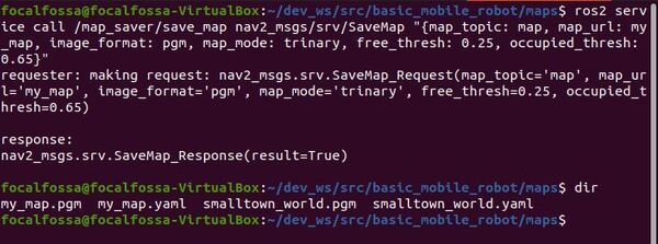
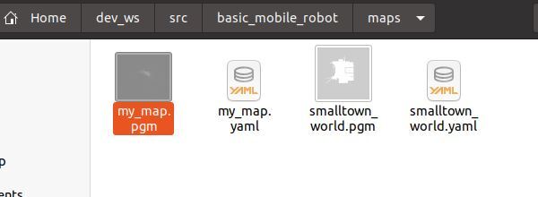
Your my_map.pgm and my_map.yaml file will save to the maps directory of your basic_mobile_robot package.
Save the Map (ROS Galactic and Newer)
If you have ROS Galactic or newer, open a new terminal window, and type:
colcon_cd basic_mobile_robot
cd maps
When you are happy with the map you have built, open a new terminal window, and type the following command to save the map:
ros2 run nav2_map_server map_saver_cli -f my_map
The syntax is:
ros2 run nav2_map_server map_saver_cli -f <map_name>
Your my_map.pgm and my_map.yaml map files will automatically save to the maps directory of your basic_mobile_robot package.
That’s it!
In the next tutorial, we will take a look at how to incorporate GPS data to create better localization. Stay tuned!