
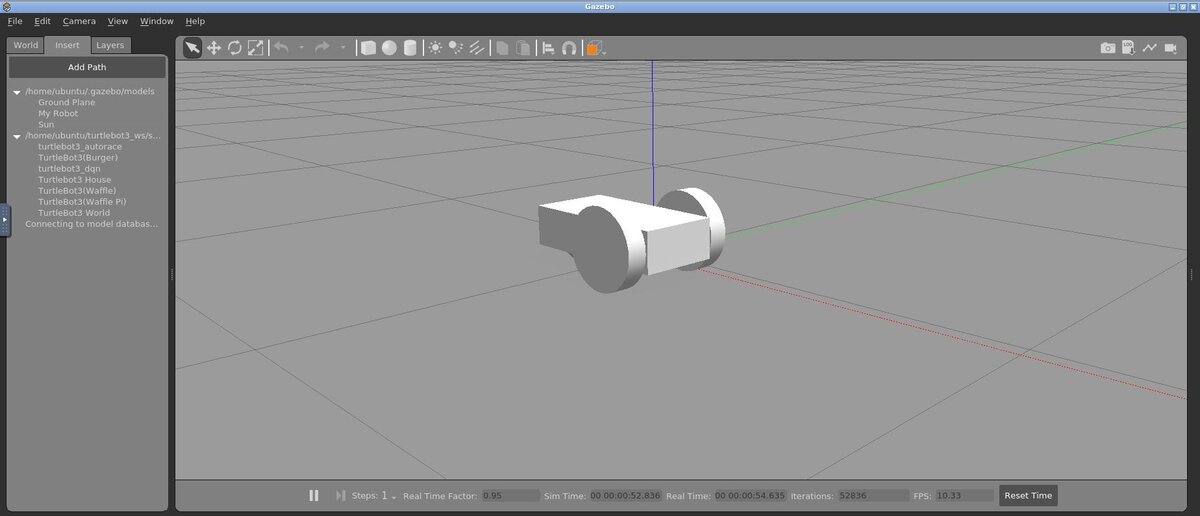
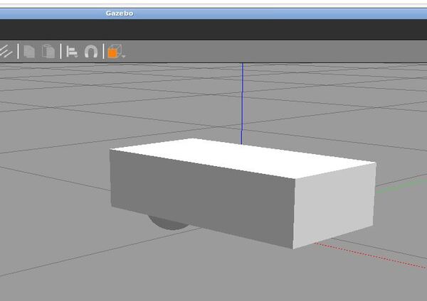
In this tutorial, we will learn how to make a model of a mobile robot in Gazebo from scratch. Our simulated robot will be a wheeled mobile robot. It will have two big wheels on each side and a caster wheel in the middle. Here is what you will build. In this case, I have the robot going in reverse (i.e. the big wheels are on the front of the vehicle):
Prerequisites
Setup the Model Directory
Here are the official instructions, but we’ll walk through all the steps below. It is important to go slow and build your robotic models in small steps. No need to hurry.
Create a folder for the model.
mkdir -p ~/.gazebo/models/my_robot
Create a model config file. This file will contain a description of the model.
gedit ~/.gazebo/models/my_robot/model.config
Add the following lines to the file, and then Save. You can see this file contains fields for the name of the robot, the version, the author (that’s you), your e-mail address, and a description of the robot.
<?xml version="1.0"?>
<model>
  <name>My Robot</name>
  <version>1.0</version>
  <sdf version='1.4'>model.sdf</sdf>

  <author>
   <name>My Name</name>
   <email>me@my.email</email>
  </author>

  <description>
    My awesome robot.
  </description>
</model>
Close the config file.
Now, let’s create an SDF (Simulation Description Format) file. This file will contain the tags that are needed to create an instance of the my_robot model.
gedit ~/.gazebo/models/my_robot/model.sdf
Copy and paste the following lines inside the sdf file.
<?xml version='1.0'?>
<sdf version='1.4'>
  <model name="my_robot">
  </model>
</sdf>
Save the file, but don’t close it yet.
Create the Structure of the Model
Now we need to create the structure of the robot. We will start out by adding basic shapes. While we are creating the robot, we want Gazebo’s physics engine to ignore the robot. Otherwise the robot will move around the environment as we add more stuff on it.
To get the physics engine to ignore the robot, add this line underneath the <model name=”my_robot”> tag.
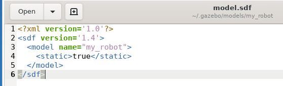
<static>true</static>
This is what you’re sdf file should look like at this stage:
Now underneath the <static>true</static> line, add these lines:
          <link name='chassis'>
            <pose>0 0 .1 0 0 0</pose>

            <collision name='collision'>
              <geometry>
                <box>
                  <size>.4 .2 .1</size>
                </box>
              </geometry>
            </collision>

            <visual name='visual'>
              <geometry>
                <box>
                  <size>.4 .2 .1</size>
                </box>
              </geometry>
            </visual>
          </link>
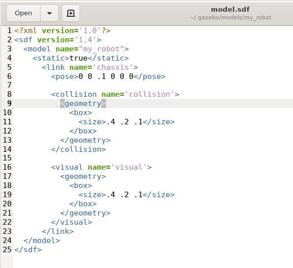
Here is how your sdf file should look now.
Click Save and close the file.
What you have done is create a box. The name of this structure (i.e. link) is ‘chassis’. A chassis for a mobile robot is the frame (i.e. skeleton) of the vehicle.
The pose (i.e. position and orientation) of the geometric center of this box will be a position of (x = 0 meters, y = 0 meters, z = 0.1 meters) and an orientation of (roll = 0 radians, pitch = 0 radians, yaw = 0 radians). The pose of the chassis (as well as the post of any link in an sdf file) is defined relative to the model coordinate frame (which is ‘my_robot’).
Remember:
- Roll (rotation about the x-axis)
- Pitch (rotation about the y-axis)
- Yaw (rotation about the z-axis)
Inside the collision element of the sdf file, you specify the shape (i.e. geometry) that Gazebo’s collision detection engine will use. In this case, we want the collision detection engine to represent our vehicle as a box that is 0.4 meters in length, 0.2 meters in width, and 0.1 meters in height.
Inside the visual tag, we place the shape that Gazebo’s rendering engine will use to display the robot.
In most cases, the visual tag will be the same as the collision tag, but in some cases it is not.
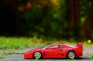
For example, if your robot car has some complex geometry that looks like the toy Ferrari car below, you might model the collision physics of that body as a box but would use a custom mesh to make the robot model look more realistic, like the figure below.
Now let’s run Gazebo so that we can see our model. Type the following command:
gazebo
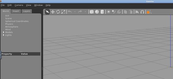
On the left-hand side, click the “Insert” tab.
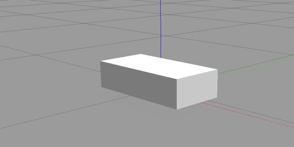
On the left panel, click “My Robot”. You should see a white box. You can place it wherever you want.
Go back to the terminal window, and type CTRL + C to close Gazebo.
Let’s add a caster wheel to the robot. The caster wheel will be modeled as a sphere with a radius of 0.05 meters and no friction.
Relative to the geometric center of the white box (i.e. the robot chassis), the center of the spherical caster wheel will be located at x = -0.15 meters, y = 0 meters, and z = -0.05 meters.
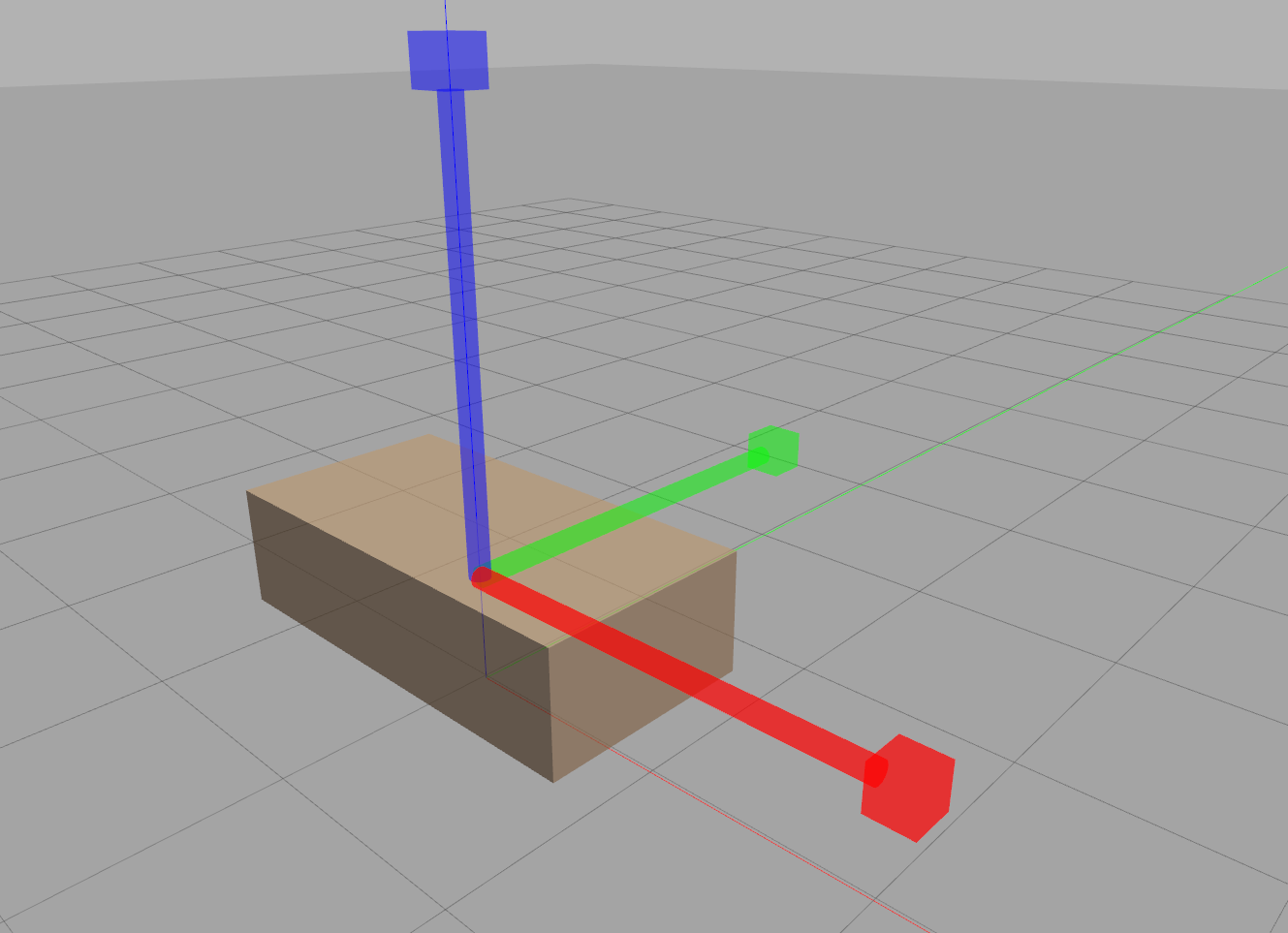
Note that when we create a box shape, the positive x-axis points towards the front of the vehicle (i.e. the direction of travel). The x-axis is that red line below.
The positive y-axis points out the left side of the chassis. It is the green line below. The positive z-axis points straight upwards towards the sky.

gedit ~/.gazebo/models/my_robot/model.sdf
Add these lines after the first </visual> tag but before the </link> tag.
          <collision name='caster_collision'>
            <pose>-0.15 0 -0.05 0 0 0</pose>
            <geometry>
                <sphere>
                <radius>.05</radius>
              </sphere>
            </geometry>

            <surface>
              <friction>
                <ode>
                  <mu>0</mu>
                  <mu2>0</mu2>
                  <slip1>1.0</slip1>
                  <slip2>1.0</slip2>
                </ode>
              </friction>
            </surface>
          </collision>

          <visual name='caster_visual'>
            <pose>-0.15 0 -0.05 0 0 0</pose>
            <geometry>
              <sphere>
                <radius>.05</radius>
              </sphere>
            </geometry>
          </visual>
Click Save and close the file.
Now relaunch gazebo, and insert the model.
gazebo
Insert -> My Robot
Go back to the terminal window, and close gazebo by typing CTRL + C.
You can now see our robot has a brand new caster wheel located towards the rear of the vehicle.
Now let’s add the left wheel. We will model this as a cylinder with a radius of 0.1 meters and a length of 0.05 meters.
gedit ~/.gazebo/models/my_robot/model.sdf
Right after the </link> tag (but before the </model> tag, add the following lines. You can see that the wheel is placed at the front of the vehicle (x=0.1m), the left side of the vehicle (y=0.13m), and 0.1m above the surface (z=0.1m). It is a cylinder that is rotated 90 degrees (i.e. 1.5707 radians) around the model’s y axis and 90 degrees around the model’s z axis.
     <link name="left_wheel">
        <pose>0.1 0.13 0.1 0 1.5707 1.5707</pose>
        <collision name="collision">
          <geometry>
            <cylinder>
              <radius>.1</radius>
              <length>.05</length>
            </cylinder>
          </geometry>
        </collision>
        <visual name="visual">
          <geometry>
            <cylinder>
              <radius>.1</radius>
              <length>.05</length>
            </cylinder>
          </geometry>
        </visual>
      </link>
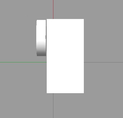
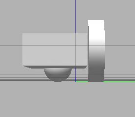
Launch Gazebo, and see how it looks. You can click the box at the top of the panel to see the robot from different perspectives.
Now, let’s add a right wheel. Insert these lines into your sdf file right before the </model> tag.
    <link name="right_wheel">
        <pose>0.1 -0.13 0.1 0 1.5707 1.5707</pose>
        <collision name="collision">
          <geometry>
            <cylinder>
              <radius>.1</radius>
              <length>.05</length>
            </cylinder>
          </geometry>
        </collision>
        <visual name="visual">
          <geometry>
            <cylinder>
              <radius>.1</radius>
              <length>.05</length>
            </cylinder>
          </geometry>
        </visual>
      </link>
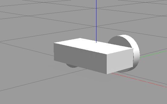
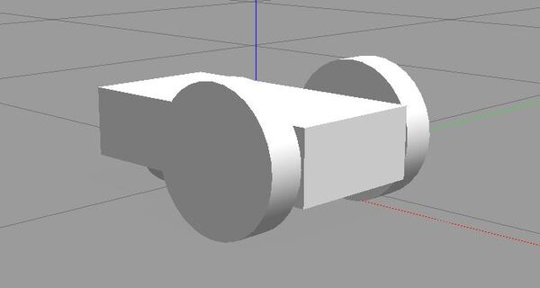
Save it, close it, and open Gazebo to see your robot. Your robot has a body, a spherical caster wheel, and two big wheels on either side.
Now let’s change the robot from static to dynamic. We need to add two revolute joints, one for the left wheel and one for the right wheel. Revolute joints (also known as “hinge joints”) are your wheels motors. These motors generate rotational motion to make the wheels move.
In the sdf file, first change this:
<static>true</static>
To this
<static>false</static>
Then add these lines right before the closing </model> tag.
      <joint type="revolute" name="left_wheel_hinge">
        <pose>0 0 -0.03 0 0 0</pose>
        <child>left_wheel</child>
        <parent>chassis</parent>
        <axis>
          <xyz>0 1 0</xyz>
        </axis>
      </joint>

      <joint type="revolute" name="right_wheel_hinge">
        <pose>0 0 0.03 0 0 0</pose>
        <child>right_wheel</child>
        <parent>chassis</parent>
        <axis>
          <xyz>0 1 0</xyz>
        </axis>
      </joint>
<child> defines the name of this joint’s child link.
<parent> defines the parent link.
<pose> describes the offset from the the origin of the child link in the frame of the child link.
<axis> defines the joint’s axis specified in the parent model frame. This axis is the axis of rotation. In this case, the two joints rotate about the y axis.
<xyz> defines the x, y, and z components of the normalized axis vector.
You can learn more about sdf tags at the official website.
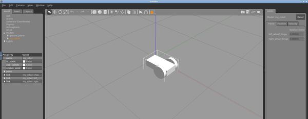
Save the sdf file, open Gazebo, and insert your model.
Click on your model to select it.
You will see six tiny dots on the right side of the screen. Click on those and drag your mouse to the left. It is a bit tricky to click on these as Gazebo can be quite sensitive. Just keep trying to drag those dots to the left using your mouse.
Under the “World -> Models” tab on the left, select the my_robot model. You should see two joints appear on the Joints tab on the right.
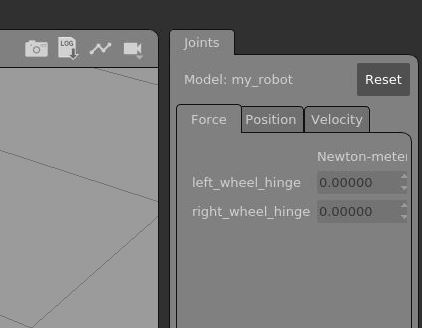
Under the Force tab, increase the force applied to each joint to 0.1 N-m. You should see your robot move around in the environment.
Congratulations! You have built a mobile robot in Gazebo.