
In this tutorial, I will show you how to calculate how much torque you need for the servo motors (i.e. joints) on a robotic arm you are trying to build.
Why is torque so important? When you want to build a robotic arm to perform some task in the world, you have to make sure that each joint of the arm (i.e. servo motor) is strong enough to lift whatever you want it to lift. In robotics jargon, the maximum weight that a robotic arm can lift is referred to as the maximum payload.
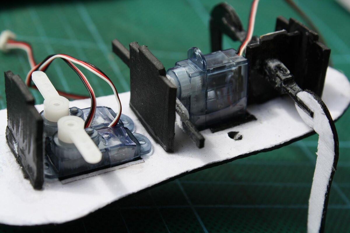
This six degree of freedom robotic arm we built here can lift a pair of sunglasses, but the servos don’t have enough torque to lift a car, for example.
What is Torque?
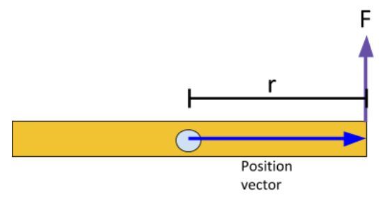
Consider this wooden rod below.

Let’s label its center of mass with a light blue circle. Imagine this blue circle is a nail that we have hammered into the wooden rod and a wall.

If we apply a force F on the end of the rod at a distance r from the center of mass, what do you think will happen?
Note that we are only concerned about the component of the force that is perpendicular to the position vector. The position vector is drawn from the axis of rotation (i.e. the blue nail) to the force vector (in blue below). The position vector must be perpendicular to the force vector.
The rod will rotate in a counterclockwise direction around the axis.
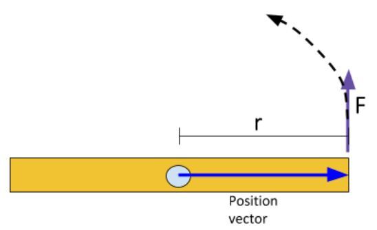
This force that is applied at a position r from the axis of rotation (which is directly out of the page) is known as torque. Torque is often represented by the Greek letter τ. The equation for torque is:
τ = r F
It is worth repeating, but with torque we are only concerned about the component of the force that is perpendicular to the position vector. Any force component that is parallel to the position vector doesn’t generate torque.
For example, imagine we applied force to the end of the rod at an angle like this:
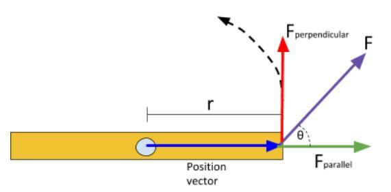
The torque in this case just takes into account that red line above. Here, the equation for the torque is:
sin(θ) = Fperpendicular / F … using trigonometry
Fsin(θ) = Fperpendicular
Therefore,
τ = r F sin(θ)
The official metric (SI) units of torque is the Newton-meter (Nm). However in datasheets for servo motors, you’ll often see ounce-force-inch (oz-in) or kilogram-force centimeter (kg-cm).
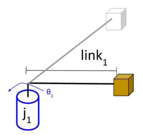
In the real world, a servo motor’s axis is the blue nail. This is the robotic arm’s joint. The orange bar is the link of a robotic arm. The force F is the force acting on an object (that the robotic arm is trying to lift) due to gravity.
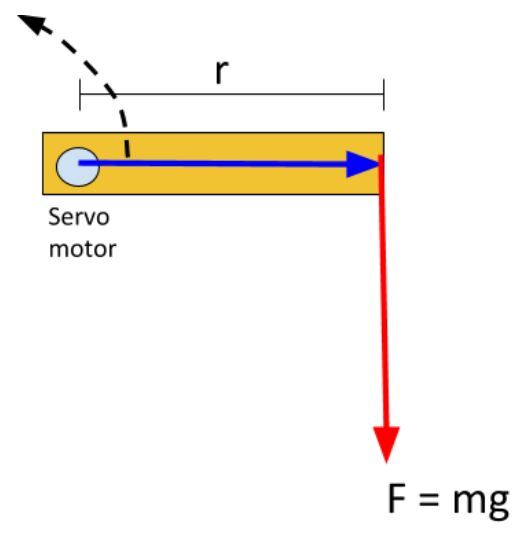
F = mass * g
Where m is the mass the servo motor has to lift, and g is the acceleration due to gravity (9.80665 m/s2).
The torque for this setup above is:
τ = m * g * r
Example 1
If you see a servo with a torque of 35kg-cm, what does that mean?
Typically, when you see a value like 35 kg printed on a servo motor, what they are referring to is the stall torque, which, in this case, is 35 kg-cm. Stall torque is the torque load that causes a servo motor to “stall” or stop rotating.
A stall torque of 35 kg-cm means that the servo motor will stop rotating when it is trying to move a 35 kg weight at a radial distance of 1.0 cm.
In the example below, we will assume the orange link has a mass of 0 kg.

In case you’re wondering, what the force F is:
F = m * g = 35 kg * 9.80665 m/s2
F = 35 kg * 9.80665 m/s2
F = 343.2 N
Where N stands for newtons. Note that 1 N = 9.80665 kg.
Example 2
Let’s say the servo of the robotic arm rotates a bit, counterclockwise.
What is the torque in this case?
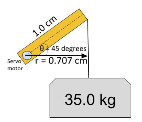
τ = r F
τ = (1.0 cm * cos(45°)) * (343.2 N)
τ = (.01 m * cos(45°)) * (343.2 N)
τ = (.00707m) * (343.2 N)
τ = 2.427 Nm
1 Nm is equal to 10.197162129779 kg-cm.
Therefore,
τ = 24.75 kg-cm
So, you can see that when the arm is extended out parallel to the ground surface, the torque is higher than when the arm is bent.
This makes a lot of sense. Imagine holding your arm stretched out horizontally and trying to hold a bucket of water in place while trying not to bend your elbow. It would be pretty difficult!
Accounting for the Force of Gravity
In the example above, we have accounted for the force of gravity when calculating our torque requirements. However, we assumed that the links have no weight. In reality they do.
Consider this diagram of a robotic arm below. It has four servo motors and a gripper on the end (at right). Each servo motor (i.e. joint) is connected by a link (typically a metal piece like you see in this six degree of freedom robotic arm here).
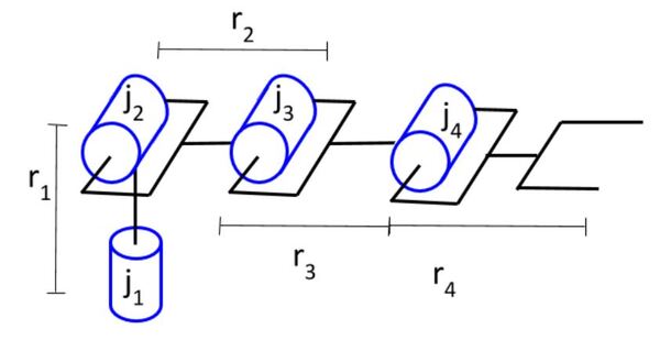
To calculate the torque requirement, we start at the end effector (i.e. gripper) of the robotic arm and then work our way to the base of the robot. We need to account for all the pieces of the robot that are impacted by gravity:
- Weight of the link
- Weight of the joint
- Weight of the object being lifted (e.g. the box below)
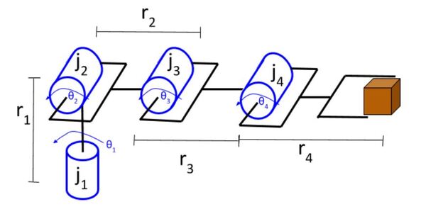
Let’s start with joint 4. Joint 4 has to be strong enough to lift the box as well as link 4.
Box:
- The center of mass of the box is located at a distance r4 from the axis of rotation of joint 4.
- The force of gravity acting on the box is equal to mbox * g. (where m means mass).
- The torque due to the box is therefore r4 * mbox * g.
Link 4:
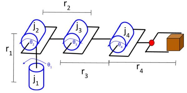
- The center of mass of the link is that red dot above. It is located at a distance r4/2 from the axis of rotation of joint 4.
- The force of gravity acting on link 4 is equal to mlink4 * g (note that the product of mass and the gravitational acceleration constant is also known as the “weight”).
- The torque due to the box is therefore (1/2) * r4 * mlink4 * g.
Therefore:
Torque4 = (r4 * mbox * g) + ((1/2) * r4 * mlink4 * g)
Let’s now do one more. We’ll do joint 3. We place a red dot in the center of mass of link 3.
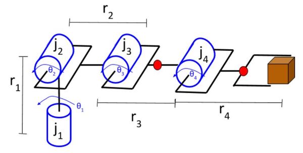
Joint 3 has to be strong enough to lift the following components:
- Box…………((r3 + r4) * mbox * g)
- Link 4….…..((r3 + r4/2) * mlink4 * g)
- Joint 4……..(r3 * mjoint4 * g)
- Link 3………(r3/2 * mlink4 * g)
Therefore:
Torque3 = ((r3 + r4) * mbox * g) + ((r3 + r4/2) * mlink4 * g) + (r3 * mjoint4 * g) + (r3/2 * mlink4 * g)
You keep doing this for the other joints.
Accounting for Angular Acceleration
The force of gravity on the links and payload (i.e. the box) is only part of the calculation of the torque requirement for a motor. We want our robotic arm to move and do useful work in the world…not just sit there with its arm stretched out, holding a box in place.
There is a torque required for a joint to move (i.e. generate angular acceleration) a link (or payload) from a rest position. Therefore, the total torque requirement for a servo is:
Torque Required By a Servo Motor = (Torque Due to Force of Gravity on Links and Payload) + (Torque Due to Angular Acceleration of Links and Payload)
This torque due to angular acceleration is calculated using the following equation:
τ = Iα
where I is the rotational inertia (or moment of inertia), and α is the angular acceleration around an axis.
The value for I will vary depending on what is generating the angular acceleration (e.g. solid cylinder, thin rod, slab, etc.). Inertia is the “resistance an object has to any change in its velocity.” Therefore, rotational inertia in the case of a servo motor is the resistance the motor has to any change in its velocity.
The units for rotational inertia are kg-m2. The unit for angular acceleration is rad/s2.
Example
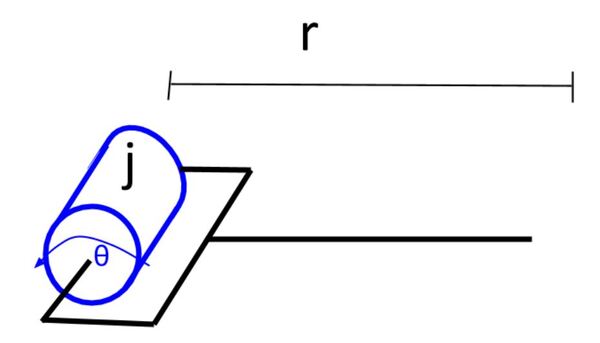
Consider this joint below that is connected to a link. In this case, the motor will rotate counterclockwise in a direction that is at a 90 degree angle to the force of gravity (which is straight down). The only torque we have here is the torque required to generate angular acceleration.
τ = Iα
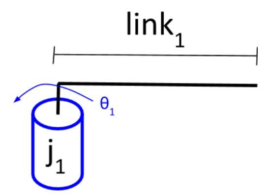
I in this case will be the sum of the rotational inertia of the motor and the link.
I = Imotor + Ilink1
You can find the rotational inertia of the motor (Imotor) in the datasheet for the motor (do a Google search for the datasheet). The rotational inertia of the link (Ilink1) can be described as the rotational inertia of a rod of some length L and mass m, rotating about one end. The equation is as follows:
Ilink1=(1/3)*m*L2
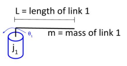
α, the angular acceleration, will be the same for both the motor and the link since they are connected to each other.
How do we find α?
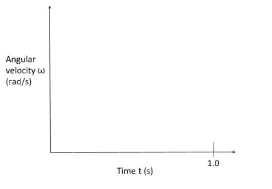
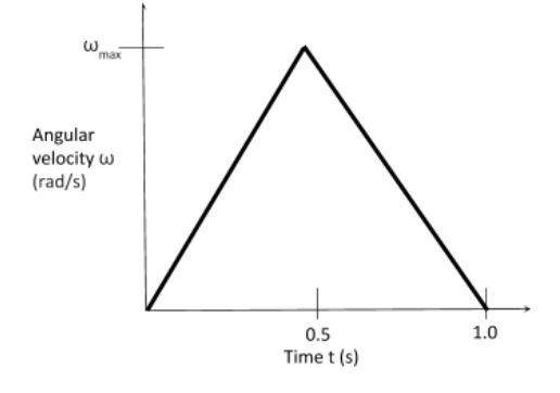
Let’s assume that we want the motor to move 90° in 1.0 second and then stop (e.g. common in pick and place tasks). We can draw a graph of angular velocity ω (radians/second) vs. time t (seconds).
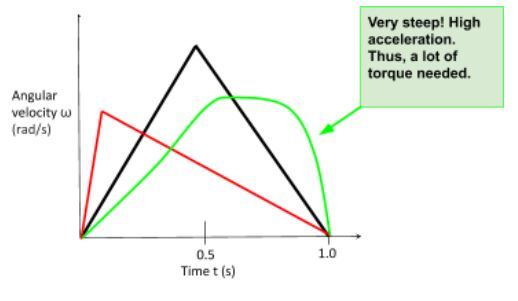
We want to minimize acceleration as much as possible so that we minimize the torque requirements for our servo motor. We could have any velocity curve we want, but the curve that minimizes acceleration is the one that increases linearly from rest, reaches a peak at the halfway point, and then decreases linearly from there.
The reason why this curve below gives the minimum acceleration is because acceleration is the slope of the velocity curve (i.e. change in angular velocity/change in time = angular acceleration).
You can see that the magnitude of the slope is minimized on the black curve. The red and green curves get steep in some parts, which means the angular acceleration is high (and thus more torque is needed for the servo motor).
What is the required area underneath this curve below? The area of the curve (i.e. triangle) is equal to the distance the servo motor needs to move.
The formula for the area of a triangle (Atriangle) is:
Atriangle = (1/2)*(base)*(height)
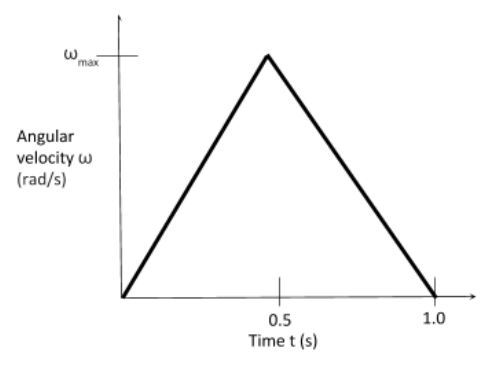
The distance the servo motor needs to move is 90°, which is equal to π/2 radians.
π/2 = (1/2)*(1.0)*(ωmax)
ωmax = π radians/second
Since α is the slope of the curve, we know that it is:
α = (change in y/ change in x) = (π/0.5) = 2π rad/s2
Now, we have all the numbers we need to calculate the required torque:
τ = (Imotor + (1/3)*m*L2) * (2π)
Let’s assume:
- Imotor = 0 kg-m2 (we’ll assume the rotational inertia of the motor is negligible compared to the link, but you would typically get this value in the motor’s datasheet)
- L = 0.75 m
- m = 1.2 kg
τ = ((1/3)*(1.2kg)*(0.75 meters)2) * (2π rad/s2)
τ = 1.414 kg-m2/s2 = 1.414 Nm = 14.410 kg-cm = 200 oz-in
Now, that we’ve identified the torque requirements for the motor in motion (we covered the stationary motor case in the previous section of this post), we need to make sure we select a motor that will be able to exert 14.410 kg-cm of torque at all of the speeds in the curve below.
So the next step is to take a motor that has a stall torque greater than 14.410 kg-cm and plot the torque vs. speed curve. We need to make sure that both the maximum torque and maximum speed (i.e. ωmax) fall under this curve; otherwise, we could damage our motors.
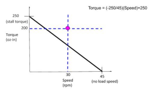
Let’s suppose we searched around on the Internet at various electronics stores and found a motor with a no load speed of 45 RPM and a stall torque of 250 oz-in (18 kg-cm). Let’s draw the torque vs. speed curve. Note that the “no load speed” is the revolutions per minute of a motor when it is running at top speed with nothing attached to it.
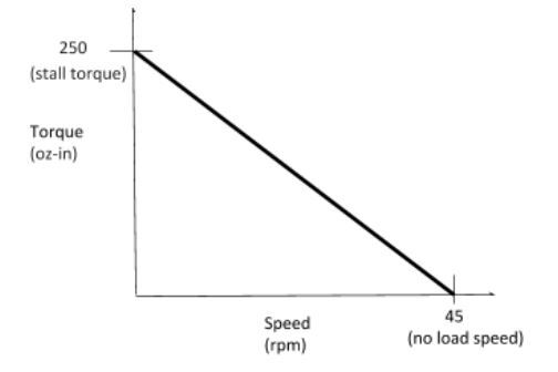
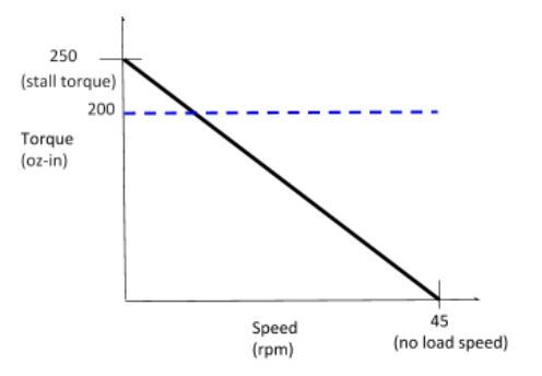
From our analysis, we calculated that we need 200 oz-in of torque, so I’ll draw that on the graph as a blue line.
ωmax = π radians/second
1 Radians Per Second = 9.5493 Revolutions Per Minute
ωmax = π radians/second * 9.5493 rpm/(radians/second) = 30 rpm
Let’s draw that on the curve.
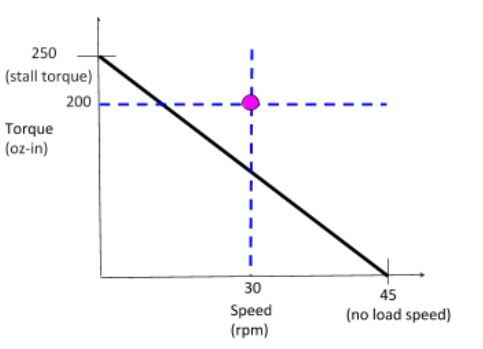
It looks like that pink dot is above the curve, so we might need a stronger motor. Let’s double check to see if that point is, in fact, above our torque vs. speed curve.
Torque = (-250/45)*(30) + 250 = 83 oz-in
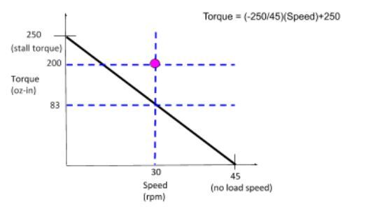
We see that the motor generates 83 oz-in of torque when the speed is 30rpm. However, we need to have 200 oz-in of torque, so this motor is not strong enough for our project.
Now, let’s see if we found a motor with the following specifications.
- No-load speed = 100 rpm
- Stall Torque = 350 oz-in
Do this work for our purposes? Let’s do the math.
Torque = (-350/100)*(30) + 350 = 245 oz-in
Since 245 > 200, this motor works for our purposes.
However, in our analysis we have not taken into account the rotational inertia of the motor, and we have assumed that there is no payload attached to the link. So, in a real-world use case, we need to account for those by incorporating them into our original calculation of I (i.e. the rotational inertia).
Accounting for Angular Acceleration and the Force of Gravity
Now let’s look at an example where we need to take both angular acceleration and the force of gravity into account in order to calculate the torque requirement.
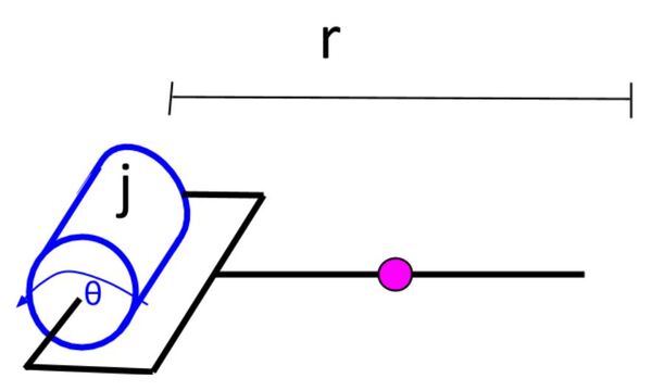
We will reposition the joint-link combination we worked with in the previous section so that the body of the motor is now parallel to the surface. Here is how that looks:
Here we have two torques:
- Acceleration of the Link: τ = Iα
- Gravity: τ = r F
Adding the two torques we have:
τ = Iα + mass * g * (r/2) * cos(θ)
Where r/2 is the distance from the axis of rotation to the center of mass of the link. The center of mass of the link is noted with a pink circle below.
The mass of the link is 1.2 kg, and the link length is 0.75 meters. In the worst case, cos(θ) = 1. Therefore, the amount of torque that the motor needs to have the link overcome the downward force of gravity is:
mass * g * (r/2) * cos(θ) = (1.2 kg)(9.8 m/s2)(0.75/2) = 4.41 Nm = 624 oz-in
You can see how the torque required to overcome the force of gravity is more than 3x the required torque to accelerate a link from rest (which we calculated as 200 oz-in).
Total torque required = 200 oz-in + 624 oz-in = 824 oz-in
Adding a Payload to the Robotic Arm
Now, let’s assume the robotic arm has something at the end of it that it needs to carry. We call this a payload.
If you go to this list at Wikipedia, you will see that this object can be considered a “point mass”. The equation for rotational inertia for a point mass is:
I = Mr2
Where M = mass of the object, and r is the distance from the rotational axis to the center of mass of the object.
Earlier we found the torque required to produce angular acceleration for the link. That was:
τ = (Imotor + (1/3)*m*L2) * (2π)
τ = ((1/3)*(1.2kg)*(0.75 meters)2) * (2π rad/s2)
τ = 1.414 kg-m2/s2 = 1.414 Nm = 14.410 kg-cm = 200 oz-in
Now we need to add the rotational inertia of the object attached to the link. Let’s assume the object has a mass of 1.2kg (just like the mass of the link). The equation becomes:
τ = ((1/3)*(1.2kg)*(0.75 meters)2 + 1.2 kg * (0.75)2) * (2π rad/s2)
τ = 5.655 kg-m2/s2 = 5.655 Nm = 57.665 kg-cm = 800.8 oz-in
Now let’s go back here:

We had:
τ = Iα + mass * g * (r/2) * cos(θ)
τ = Iα + 4.41 Nm
We also have to add the torque of the payload due to gravity.
τ = Iα + 4.41 Nm + (1.2 kg)(9.8 m/s2)(0.75)
τ = Iα + 4.41 Nm + 8.82 Nm
τ = Iα + 13.23 Nm
τ = Iα + 1873.5 oz-in
Therefore,
τ = Total amount of torque required to move the link and payload
= (torque needed for angular acceleration) + (torque to overcome gravity)
= 800.8 oz-in + 1873.5 oz-in
= 2674.3 oz-in
You now have the fundamentals to expand this calculation to multi-link robotic arms. That’s it for now. Keep building!
References
- Here is a handy calculator that helps you select the appropriate servo motor for each joint of your robotic arm.
- Khan Academy has a good comprehensive short course on torque.
- Professor Angela Sodemann has a great tutorial on her site RoboGrok.com that covers torque requirements for manipulators