
In this tutorial, we will cover the basics of the standard coordinate frames (i.e. x,y,z axes) for mobile robots that use ROS. We will also cover how to set up coordinate frames for a basic two-wheeled differential drive mobile robot.
Prerequisites
You know how to create a ROS launch file.
Why Coordinate Frames Are Important?
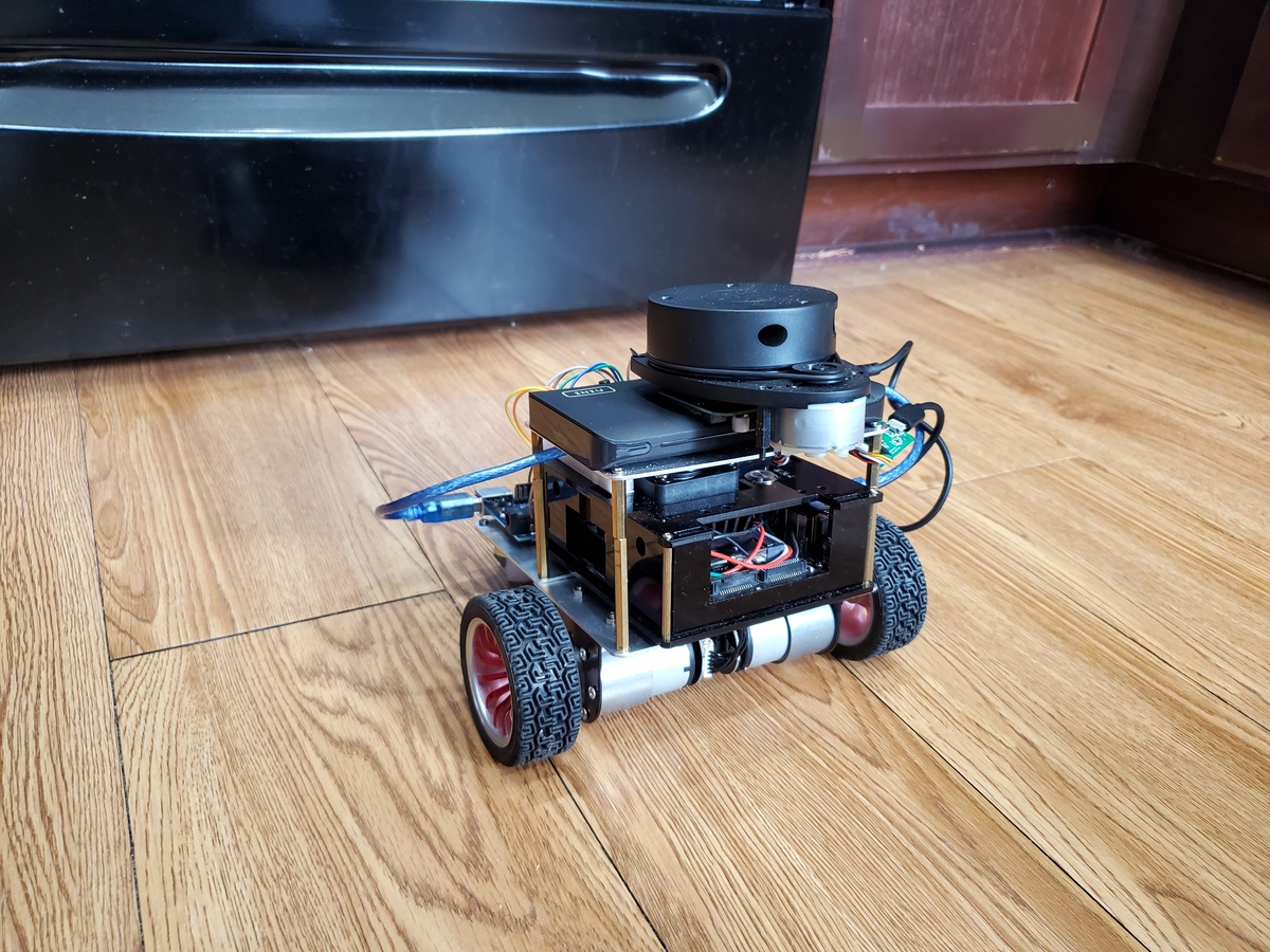
Suppose we have a LIDAR mounted on top of a wheeled robot like in the cover image of this tutorial. The job of the LIDAR is to provide data about the distances to objects in the environment.
You will notice how the LIDAR is not located at the center point of the robot. It is mounted slightly forward from the center of the robot…perhaps 10 cm from the center point of the robot’s base.
In a real-world scenario, in order for the robot to avoid obstacles as it moves around in the environment, we need to convert a detected object’s coordinates in the LIDAR coordinate frame to equivalent coordinates in the robot base’s frame.
The LIDAR might detect an object at 100 cm away, for example…but what does that mean in terms of the robot base frame? If the LIDAR is mounted on the front part of the robot, 10 cm forward from the center point of the robot’s base frame, the object might actually be 110 cm away from the robot.
You can see why coordinate frames and being able to transform data from one coordinate frame to another is important for accurate autonomous navigation.
Check out the first part of this post at the official ROS website which has a good discussion of why coordinate frames are so important for a robot.
Standard Coordinate Frames in ROS for a Mobile Robot
Below are the standard coordinate frames for a basic two wheeled differential drive robot.
- The red arrows represent the x axes
- The blue arrows represent the z axes
- The green dots (into the page) represent the y axes.
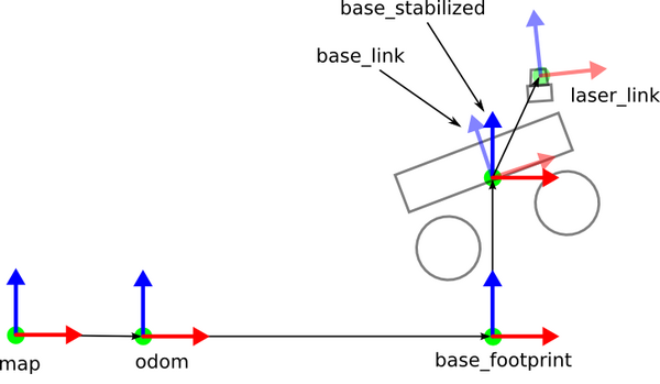
The official ROS documents have an explanation of these coordinate frames, but let’s briefly define the main ones.
- map frame has its origin at some arbitrarily chosen point in the world. This coordinate frame is fixed in the world.
- odom frame has its origin at the point where the robot is initialized. This coordinate frame is fixed in the world.
- base_footprint has its origin directly under the center of the robot. It is the 2D pose of the robot. This coordinate frame moves as the robot moves.
- base_link has its origin directly at the pivot point or center of the robot. This coordinate frame moves as the robot moves.
- laser_link has its origin at the center of the laser sensor (i.e. LIDAR). This coordinate frame remains fixed (i.e. “static”) relative to the base_link.
If you have other sensors on your robot, like an IMU, you can have a coordinate frame for that as well.
Static Transform Publisher
How can we automatically convert data that is published in one coordinate frame to equivalent data in another coordinate frame? For example, suppose we have an object at coordinate (x=3.7, y=1.23, z = 0.0) in the map coordinate frame. We want to navigate the robot to this object. What is the object’s position relative to the base_link coordinate frame?
Fortunately, ROS has a package called tf to handle all these coordinate transforms for us.
For coordinate frames that don’t change relative to each other through time (e.g. laser_link to base_link stays static because the laser is attached to the robot), we use the Static Transform Publisher.
For coordinate frames that do change relative to each other through time (e.g. map to base_link), we use tf broadcasters and listeners. A lot of ROS packages handle these moving coordinate frame transforms for you, so you often don’t need to write these yourself.
Examples
Let’s take a look at some examples of how to set up static transform publishers in ROS. These static transform publishers will typically appear inside the launch file for whatever robot you’re working on.
Here is the syntax:
static_transform_publisher x y z yaw pitch roll frame_id child_frame_id period_in_ms
From the ROS website: “Publish a static coordinate transform to tf using an x/y/z offset in meters and yaw/pitch/roll in radians. (yaw is rotation about Z, pitch is rotation about Y, and roll is rotation about X). The period, in milliseconds, specifies how often to send a transform. 100ms (10hz) is a good value.”
Map to Odom
If we want, for example, the map and odometry frame to be equivalent, here is the code you would write inside a ROS launch file:
<node pkg="tf" type="static_transform_publisher" name="map_to_odom" args="0 0 0 0 0 0 map odom 30" />
map -> odom transform tells us the position and orientation of the starting point of the robot (i.e. odom coordinate frame, which is the child) inside the map’s coordinate frame (i.e. the parent).
In our example above, we assume that the odom frame does not move relative to the map frame over time.
Odom to Base Footprint
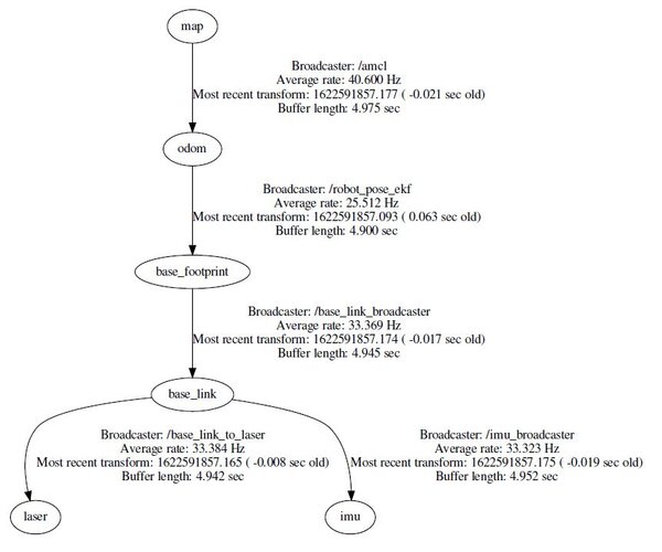
odom -> base_footprint transform is not static because the robot moves around the world. The base_footprint coordinate frame will constantly change as the wheels turn. This non-static transform is often provided in packages like the robot_pose_ekf package.
Base Footprint to Base Link
base_footprint -> base_link is a static transform because both coordinate frames are fixed to each other. The robot moves, and the coordinate frame of its “footprint” will move.
<node pkg="tf" type="static_transform_publisher" name="base_link_broadcaster" args="0 0 0.09 0 0 0 base_footprint base_link 30" />
In this case above, we assume that the origin of the base_link coordinate frame (i.e. center of the robot) is located 0.09 meters above its footprint.
Base Link to Laser
base_link -> laser transform gives us the position and orientation of the laser inside the base_link’s coordinate frame. This transform is static.
<node pkg="tf" type="static_transform_publisher" name="base_link_to_laser" args="0.06 0 0.08 0 0 0 base_link laser 30" />
We assume that the laser is located 0.06 meters forward of the center of the robot and 0.08 meters above the center of the robot.
Base Link to IMU
base_link -> imu transform gives us the position and orientation of the IMU (inertial measurement unit…commonly a BNO055 sensor) inside the base_link’s coordinate frame. This transform is static.
<node pkg="tf" type="static_transform_publisher" name="imu_broadcaster" args="0 0.06 0.02 0 0 0 base_link imu 30" />
That’s it for the basics of coordinate frames and static transform publishers in ROS. Keep building!