
In this tutorial, I will show you how to set up the odometry for a mobile robot. This tutorial is the second tutorial in my Ultimate Guide to the ROS 2 Navigation Stack (also known as Nav2).
The official tutorial for setting up odometry is on this page, but I will walk you through the entire process, step-by-step.
You can get the entire code for this project here.
Let’s get started!
Prerequisites
- You have completed this tutorial.
Odometry in ROS 2
In robotics, odometry is about using data from sensors to estimate the change in a robot’s position, orientation, and velocity over time relative to some point (e.g. x=0, y=0, z=0). Odometry information is normally obtained from sensors such as wheel encoders, IMU (Inertial measurement unit), and LIDAR.
In ROS, the coordinate frame most commonly used for odometry is known as the odom frame. Just like an odometer in your car which measures wheel rotations to determine the distance your car has traveled from some starting point, the odom frame is the point in the world where the robot first starts moving.
A robot’s position and orientation within the odom frame becomes less accurate over time and distance because sensors like IMUs (that measure acceleration) and wheel encoders (that measure the number of times each wheel has rotated) are not perfect.
For example, imagine your robot runs into a wall. Its wheels might spin repeatedly without the robot moving anywhere (we call this wheel slip). The wheel odometry would indicate a further distance traveled by the robot than reality. We have to adjust for these inaccuracies.
To learn all about coordinate frames for mobile robots (including the odom frame), check out this post.
To correct for the inaccuracies of sensors, most ROS applications have an additional coordinate frame called map that provides globally accurate information and corrects drift that happens within the odom frame.
The ROS 2 Navigation Stack requires:
- Publishing of nav_msgs/Odometry messages to a ROS 2 topic
- Publishing of the coordinate transform from odom (parent frame) -> base_link (child frame) coordinate frames.
Getting both of these pieces of data published to the ROS system is our end goal in setting up the odometry for a robot.
Simulate the Odometry System Using Gazebo
Let’s set up the odometry for the simulated robot we created in the last tutorial. We will use Gazebo, an open-source 3D robotics simulator.
Set Up the Prerequisites
Gazebo is automatically included in ROS 2 installations. To test that Gazebo is installed, open a new terminal window, and type:
gazebo
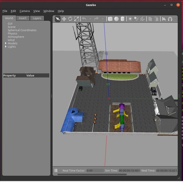
You should see an empty world:
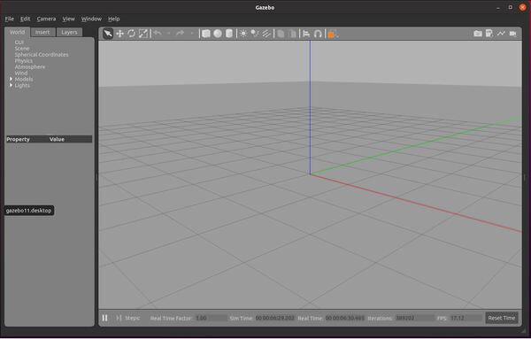
If you don’t see any output after a minute or two, follow these instructions to install Gazebo.
Close Gazebo by going to the terminal window and pressing CTRL + C.
Now, open a new terminal window, and install the gazebo_ros_pkgs package.
sudo apt-get update
sudo apt-get upgrade
sudo apt install ros-foxy-gazebo-ros-pkgs
The syntax for the above command is:
sudo apt install ros-<ros2-distro>-gazebo-ros-pkgs
….where you replace <ros2-distro> with the ROS 2 distribution that you are using. I am using ROS 2 Foxy Fitzroy, so I use “foxy”.
Create an SDF File for the Robot
Later in this tutorial series, we will be using the robot_localization package to enable the robot to determine where it is in the environment. To use this package, we need to create an SDF file.
Why should we create an SDF file instead of using our URDF File? In working with ROS for many years, I have found that URDFs don’t always work that well with Gazebo.
For example, when I ran through the official ROS 2 Navigation Stack robot localization demo, I found that the filtered odometry data was not actually generated.
So, we need to use an SDF file for Gazebo stuff and a URDF file for ROS stuff. We will try to make sure our SDF file generates a robot that is as close as possible to the robot generated by the URDF file.
Open a new terminal window, and type:
cd ~/dev_ws/src/basic_mobile_robot/models
If you have colcon_cd set up, you can also type:
colcon_cd basic_mobile_robot
cd models
Create Model.config
Let’s create a folder for the SDF model.
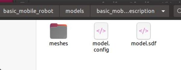
mkdir basic_mobile_bot_description
Move inside the folder.
cd basic_mobile_bot_description
Create a model.config file.
gedit model.config
Type this code inside this model.config file. You can see this file contains fields for the name of the robot, the version, the author (that’s you), your email address, and a description of the robot.
Save the file, and then close it.
Create Model.sdf
Now, let’s create an SDF (Simulation Description Format) file. This file will contain the tags that are needed to create an instance of the basic_mobile_bot model. We want to build it so that it is as close to the URDF robot representation as possible. Our robot has three wheels: two wheels in the back and a caster wheel in the front.
The official tutorial for creating an SDF file is here (other good tutorials are here and here), but let’s do this together below. I put a lot of comments in the SDF file so that you can see what is going on. Don’t be intimidated by how the file looks. Just go through it slowly, one line at a time, section by section. There is no hurry.
Type the following command:
gedit model.sdf
Here is my sdf file. You can copy and paste those lines inside your sdf file.
Save the file and close it to return to the terminal.
You’ll notice there are some slight differences between the URDF and the SDF file formats.
You can see in the SDF file that we use an IMU sensor plugin to simulate IMU data. And, instead of using wheel encoders to calculate odometry from the motion of the wheels, we use Gazebo’s differential drive plugin and the joint state publisher plugin.
The differential drive plugin will subscribe to velocity commands over the /cmd_vel topic and will publish odometry information to the /wheel/odometry topic.
Remember, a differential drive robot is a mobile robot whose motion is based on two separately driven wheels that are on either side of the robot’s body.
The joint state publisher plugin will publish the angles of the drive wheel joints, which are continuously changing once the robot starts moving.
In a real robotics project, to calculate the odometry system, we would use an IMU sensor, and we would use wheel encoders. In this real-world project for example, I used wheel encoder data to generate an odometry message.
Add Meshes Folder
Now let’s have our robot look more realistic by adding a mesh to the base of the robot.
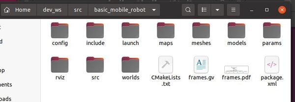
Open the file explorer by clicking on the Files icon on the left side of your terminal.
Go to your basic_mobile_robot package.
Copy the meshes folder.
Paste the meshes folder inside the ~/dev_ws/src/basic_mobile_robot/models/basic_mobile_bot_description folder.
Add the Path of the Model to the Bashrc File
Now we need to add the file path of the model to the bashrc file.
Open a terminal window, and type:
gedit ~/.bashrc
Add the following line to the bottom of the bashrc file:
export GAZEBO_MODEL_PATH=$GAZEBO_MODEL_PATH:/home/focalfossa/dev_ws/src/basic_mobile_robot/models/
The name of my Linux environment is focalfossa. Your environment may or may not have a different name.
Save the file and close it.
Test Your Robot
Now let’s run Gazebo so that we can see our model. Open a new terminal window, and type the following command:
gazebo
On the left-hand side, click the “Insert” tab.
On the left panel, find your robot.

You should see your robot in the empty Gazebo environment. You can place it wherever you want by clicking inside the environment.
To test the robot, open the rqt_steering program. In a new terminal window, type the following command:
rqt_robot_steering
A GUI will pop up.
Change the topic on the GUI to /cmd_vel.
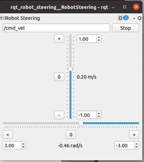
Move the sliders to move the robot forward/backward/right/left.
To see a list of ros topics, you can open a new terminal window, and type:
ros2 topic list
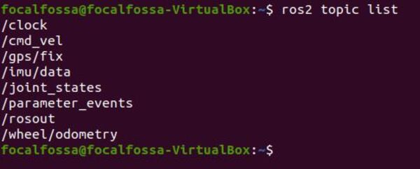
You can see that our IMU data, wheel odometry data, and GPS data are all being published by the robot.
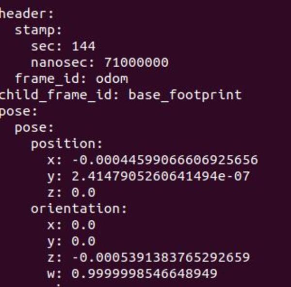
To see the wheel odometry data for example, you can type:
ros2 topic echo /wheel/odometry
You will see the current position and orientation of the robot relative to its starting point.
When you’re done, go back to the terminal windows, and type CTRL + C in all of them to close Gazebo and the steering program.
Create an SDF File for the World
Just like an SDF file can be used to define what a robot looks like, we can use an SDF file to define what the robot’s environment should look like. We want to make our robot’s environment look as realistic as possible.
This tutorial here shows you how to create your own Gazebo virtual world by dragging and dropping items into an empty world. We will walk through the process below.
Open a new terminal window, and type:
cd ~/dev_ws/src/basic_mobile_robot/worlds
If you have colcon_cd set up, you can also type:
colcon_cd basic_mobile_robot
cd worlds
Let’s create a folder for the SDF model.
mkdir basic_mobile_bot_world
Move inside the folder.
cd basic_mobile_bot_world
Create a world file.
gedit smalltown.world
Copy and paste this code inside this smalltown.world file.
Save the file, and then close it.
The world file we just created has the following six sections (from top to bottom):
- Place objects in the world
- Define the lighting of the world
- Define the physics of the world
- Define the latitude, longitude, and elevation
- Define the user perspective of the world (i.e. aerial view)
- Import our own robot
Test Your World
Now let’s run Gazebo so that we can see our world model. Open a new terminal window, and type the following command. Make sure you are inside the worlds directory of your package:
gazebo smalltown.world
You should see the world with the robot inside of it.
If you open a new terminal window, you can see that ROS automatically launched by typing the following command to see the list of active ROS topics:
ros2 topic list
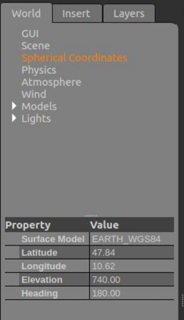
If you go back to Gazebo, you can click on the World tab, and play around with the settings for GUI (user perspective), Spherical Coordinates (latitude, longitude, elevation), Physics, etc. If you want to save these settings, you will need to record the values and modify your smalltown.world file accordingly (I prefer to do this instead of going to File -> Save World).
Once you’re finished, go back to the terminal windows, and type CTRL + C in all of them to close Gazebo.
Edit the Launch File
Now that we have our robot and our world file, we need to modify the launch file.
colcon_cd basic_mobile_robot
cd launch
gedit basic_mobile_bot_v2.launch.py
Copy and paste this code into the file.
Save the file, and close it.
Build the Package
Now build the package by opening a terminal window, and typing the following command:
cd ~/dev_ws
colcon build
Launch the Robot
Open a new terminal, and launch the robot.
cd ~/dev_ws/
ros2 launch basic_mobile_robot basic_mobile_bot_v2.launch.py
It could take a while for Gazebo to build and load the virtual world, so be patient. You might also see some warnings that say: “Warning: Invalid frame ID “drivewhl_l_link” passed to canTransform argument source_frame – frame does not exist…”. Ignore this warning. It will go away as soon as Gazebo loads.
If Gazebo is not launching properly, you can terminate Gazebo as follows:
killall gazebo
killall gzserver
killall gzclient
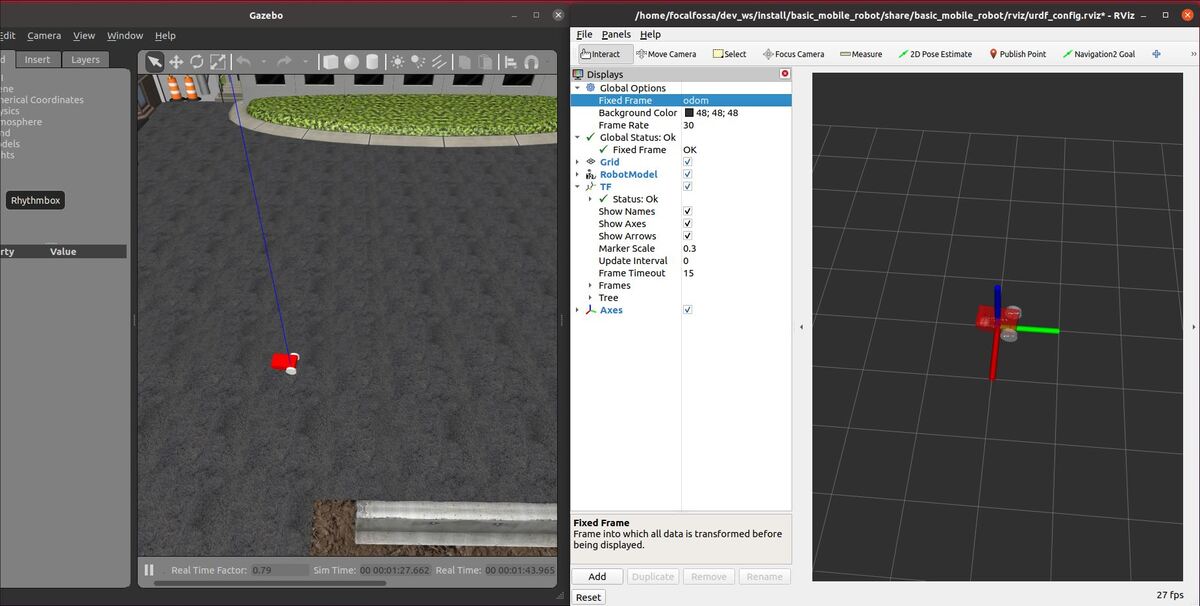
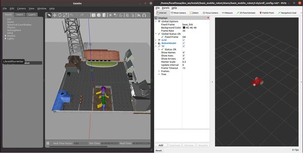
Here is the output once everything is fully loaded:
To see the active topics, open a terminal window, and type:
ros2 topic list
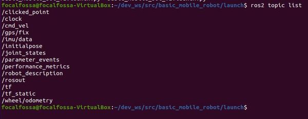
To see more information about the topics, execute:
ros2 topic info /imu/data
ros2 topic info /wheel/odometry
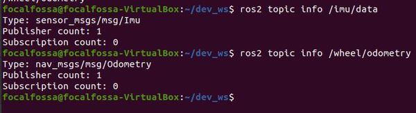
The /imu/data topic publishes sensor_msgs/Imu type messages, and the /wheel/odometry topic publishes nav_msgs/Odometry type messages. The information that is published on these topics comes from the IMU and differential drive Gazebo plugins that are defined inside our SDF file for the robot.
You will also see that both topics don’t have any subscribers yet. We will generate a robot_localization node in the next tutorial that will subscribe to both of these topics to provide a fused, locally accurate and smooth odometry information for the ROS 2 Navigation Stack.
When you’re finished, press CTRL+C in all terminal windows to stop all processes.
Troubleshooting
If you see an error that says “Warning: TF_OLD_DATA ignoring data from the past for frame”, it means that you need to make sure that all nodes are running on simulated time.
It is likely that your robot state publisher has not had the use_sim_time parameter set to True.
You can also type the following command (when ROS 2 is shutdown) to see if there are any ROS nodes that are running that shouldn’t be running. Often, you may have multiple joint state publishers that are conflicting with each other.
ros2 topic list
If you have a ROS 2 process that is running, be sure to kill it. Then restart the launch file.
In my launch file basic_mobile_bot_v2.launch.py, you can see how I set the simulated time to true for this node.
That’s it!
In our next tutorial, I will show you how to fuse the information from your IMU sensor and wheel odometry to create a smooth estimate of the robot’s location in the world. We call this sensor fusion.