
In this tutorial, we will set up the LIDAR sensor for a simulated mobile robot.
This tutorial is the fourth tutorial in my Ultimate Guide to the ROS 2 Navigation Stack (also known as Nav2).
You can get the entire code for this project here.
If you are using ROS Galactic or newer, you can get the code here.
Let’s get started!
Prerequisites
You have completed the first three tutorials of this series:
- How to Create a Simulated Mobile Robot in ROS 2 Using URDF
- Set Up the Odometry for a Simulated Mobile Robot in ROS 2
- Sensor Fusion Using the Robot Localization Package – ROS 2
Modify the SDF File for the Robot
Open a new terminal window, and type:
colcon_cd basic_mobile_robot
cd models
cd basic_mobile_bot_description
Type the following command:
gedit model.sdf
Here is my sdf file. You can copy and paste those lines inside your sdf file.
Here is the code for just the LIDAR:
  <!-- ****************************** LIDAR *****************************    -->
  <link name="lidar_link">
    <inertial>
      <pose>0.215 0 0.13 0 0 0</pose>
      <inertia>
        <ixx>0.001</ixx>
        <ixy>0.000</ixy>
        <ixz>0.000</ixz>
        <iyy>0.001</iyy>
        <iyz>0.000</iyz>
        <izz>0.001</izz>
      </inertia>
      <mass>0.114</mass>
    </inertial>

    <collision name="lidar_collision">
      <pose>0.215 0 0.13 0 0 0</pose>
      <geometry>
        <cylinder>
          <radius>0.0508</radius>
          <length>0.18</length>
        </cylinder>
      </geometry>
    </collision>

    <visual name="lidar_visual">
      <pose>0.215 0 0.13 0 0 0</pose>
      <geometry>
        <cylinder>
          <radius>0.0508</radius>
          <length>0.18</length>
        </cylinder>
      </geometry>
      <material>
        <ambient>0.0 0.0 0.0 1.0</ambient>
        <diffuse>0.0 0.0 0.0 1.0</diffuse>
        <specular>0.0 0.0 0.0 1.0</specular>
        <emissive>0.0 0.0 0.0 1.0</emissive>
      </material>
    </visual>

    <sensor name="lidar" type="ray">
      <pose>0.215 0 0.215 0 0 0</pose>
      <always_on>true</always_on>
      <visualize>true</visualize>
      <update_rate>5</update_rate>
      <ray>
        <scan>
          <horizontal>
            <samples>360</samples>
            <resolution>1.00000</resolution>
            <min_angle>0.000000</min_angle>
            <max_angle>6.280000</max_angle>
          </horizontal>
        </scan>
        <range>
          <min>0.120000</min>
          <max>3.5</max>
          <resolution>0.015000</resolution>
        </range>
        <noise>
          <type>gaussian</type>
          <mean>0.0</mean>
          <stddev>0.01</stddev>
        </noise>
      </ray>
      <plugin name="scan" filename="libgazebo_ros_ray_sensor.so">
        <ros>
          <remapping>~/out:=scan</remapping>
        </ros>
        <output_type>sensor_msgs/LaserScan</output_type>
        <frame_name>lidar_link</frame_name>
      </plugin>
    </sensor>
  </link>
Save the file and close it to return to the terminal.
You’ll notice that we added the LIDAR link, joint, and Gazebo sensor plugin. I also added an inertial section to the front caster wheel.
Make sure that you have this model.config file inside the same folder as your sdf file.
Test Your SDF File
Now let’s run Gazebo so that we can see our model. Open a new terminal window, and type the following command:
gazebo
On the left-hand side, click the “Insert” tab.
On the left panel, find your robot.
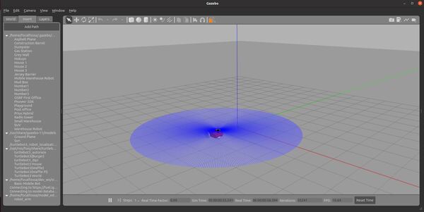
You should see your robot in the empty Gazebo environment. You can place it wherever you want by clicking inside the environment.
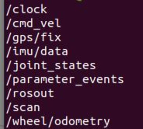
If you open a new terminal window and check out the ROS topics, you will see our /scan topic.
ros2 topic list
To check out this topic, type:
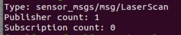
ros2 topic info /scan
You will see this /scan topic has one publisher (i.e. our LIDAR).
To see the output of the /scan topic, you type:
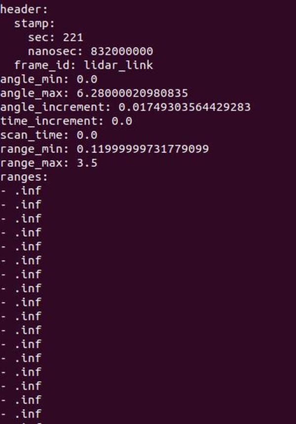
ros2 topic echo /scan
You will see that the readings for all 360 beams of the LIDAR is “.inf”, which means infinity. These readings make sense since there are no objects in the environment to detect.
Once you’re done, press CTRL+C in all windows to close everything down.
Modify the URDF File
Open a new terminal window, and type:
colcon_cd basic_mobile_robot
cd models
Create a new file named basic_mobile_bot_v2.urdf.
gedit basic_mobile_bot_v2.urdf
Inside this file, we will add a link and a joint for the LIDAR. Leave the caster wheel inertial section as-is.
Type this code inside the URDF file.
Save and close the file.
Edit the Launch File
Now that we have our robot with LIDAR, we need to modify the launch file.
colcon_cd basic_mobile_robot
cd launch
gedit basic_mobile_bot_v4.launch.py
Copy and paste this code into the file.
Save the file, and close it.
Build the Package
Now build the package by opening a terminal window, and typing the following command:
cd ~/dev_ws
colcon build
Launch the Robot
Open a new terminal, and launch the robot.
cd ~/dev_ws/
ros2 launch basic_mobile_robot basic_mobile_bot_v4.launch.py
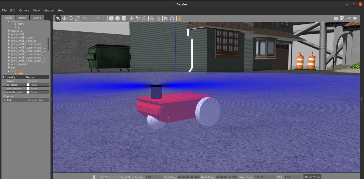
Here is the output for Gazebo:

Here is the output for RViz.
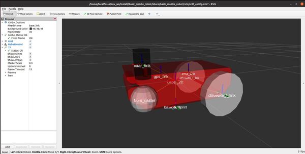
Under the TF dropdown in RViz, you should see “Transform OK” for all links.
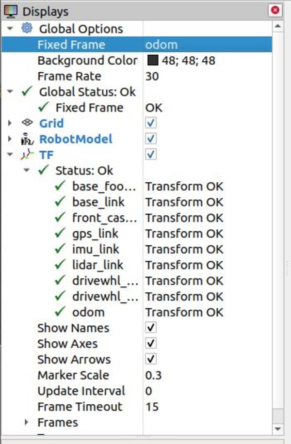
Let’s visualize the sensor readings from the LIDAR. In RViz, make sure the Fixed Frame under Global Options is set to odom.
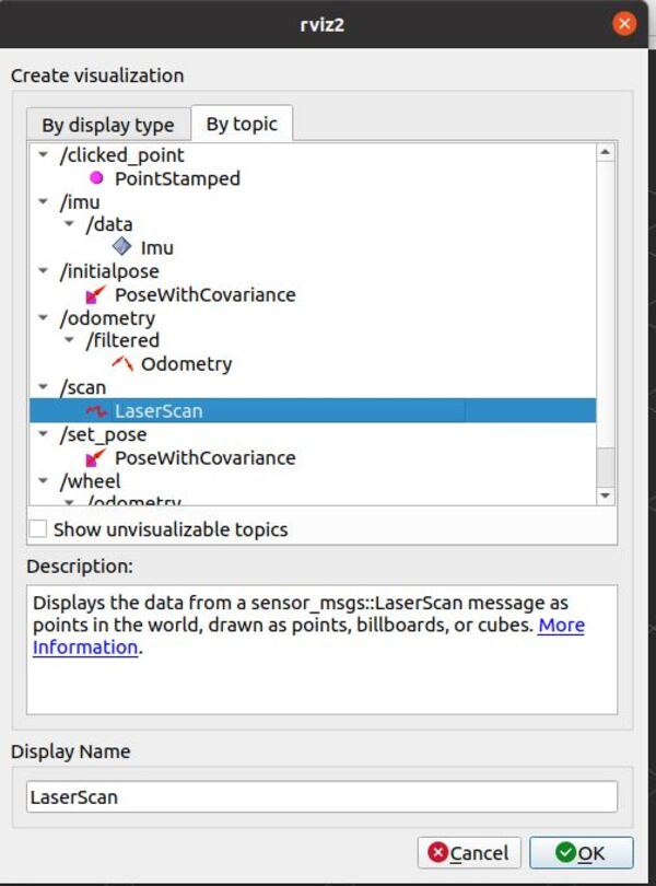
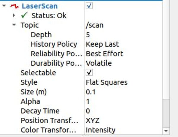
Click the Add button at the bottom-left part of the RViz window. Then go to the By topic tab, and select the LaserScan option under /scan. Then click OK.
Under the Topic dropdown menu under LaserScan in the left panel of RViz, set the Reliability Policy to Best Effort. Set the size to 0.1 m.
Now go back to a terminal window, and move the robot forward a bit so that it can start detecting that wall on the front end of the playground in Gazebo.
rqt_robot_steering
If you are using ROS 2 Galactic or newer, type:
sudo apt-get install ros-galactic-rqt-robot-steering
Where the syntax is:
sudo apt-get install ros-<ros-distribution>-rqt-robot-steering
Then type:
ros2 run rqt_robot_steering rqt_robot_steering --force-discover
You can see how the laser scan readings show up in RViz.
That’s it!
In the next tutorial, we’ll learn how to localize and create a map using this LIDAR in conjunction with the ROS 2 Navigation Stack. Stay tuned!