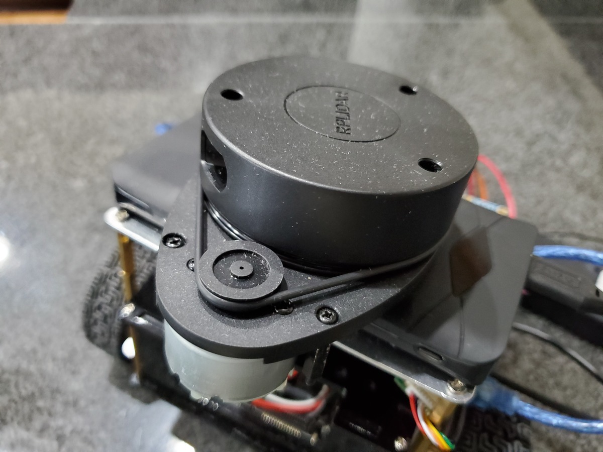
To publish LIDAR data, you are going to want to follow this tutorial. Follow all the instructions up until you reach the section entitled “Build a Map Using the Hector-SLAM ROS Package”. Don’t go beyond that point.
Create the Launch File
Once you’ve completed the step above, open a terminal window, and go to the main launch file.
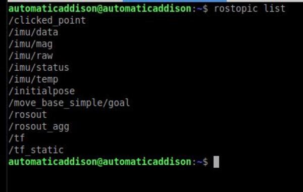
If you open a new terminal window, and type the following command, you will be able to see the active topics.
rostopic list
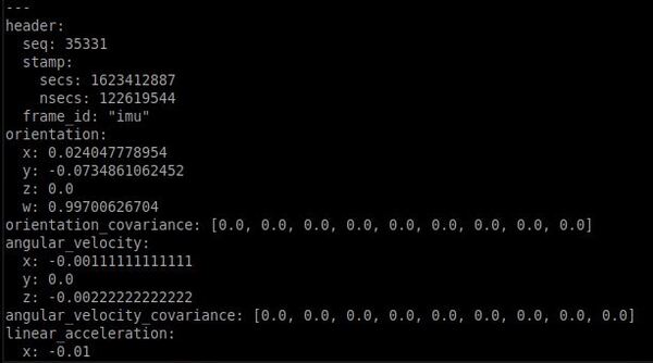
Let’s see what LIDAR data is being published to the /scan ROS topic. Open a new terminal window, and type the following command to see a single message (the number after the -n tag indicates how many messages you want to see):
rostopic echo -n1 /scan
Alternatively, you can see the full stream of messages by typing:
rostopic echo /scan
Press CTRL + C to stop the data.
Visualize the Data
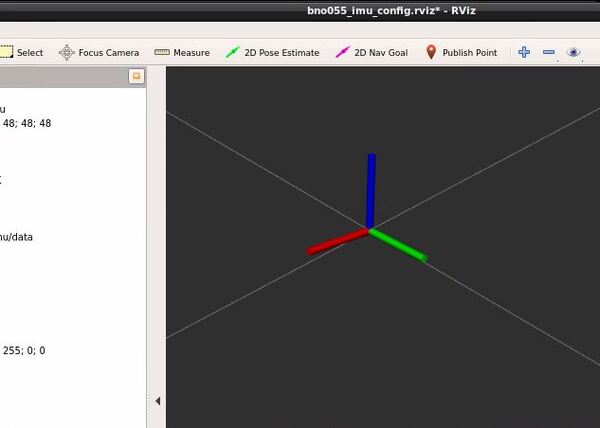
Open a new terminal window, and start rviz so we can visualize the data.
rosrun rviz rviz
Change the Fixed Frame to laser.
Click the Add button in the bottom-left of the window.
Select LaserScan, and click OK.
Set the LaserScan topic to /scan.
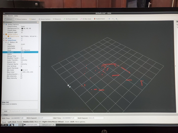
Increase the size to 0.03 so that you can see the data more easily.
Here is what you should see:
Press CTRL + C on all windows to shut everything down.
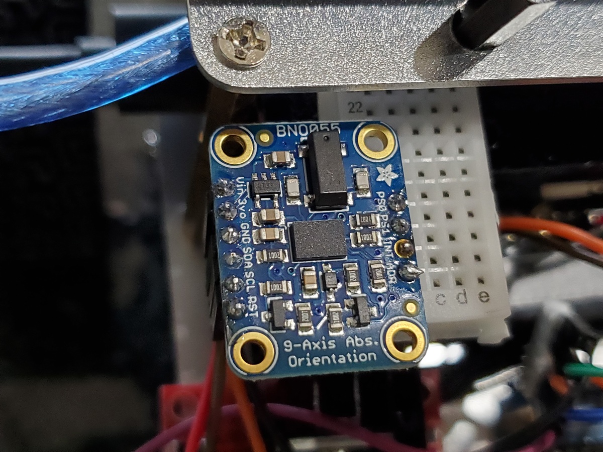
I actually prefer the BNO055 over other IMU sensors like the MPU6050. I have found that the BNO055 generates more accurate and less noisy data than the MPU6050.
Real-World Applications
This project has a number of real-world applications:
Indoor Delivery Robots
Room Service Robots
Mapping of Underground Mines, Caves, and Hard-to-Reach Environments
Robot Vacuums
Order Fulfillment
Factories
Prerequisites
You have already set up your NVIDIA Jetson Nano (4GB, B01) with ROS. You can also use an Ubuntu-enabled Raspberry Pi that has ROS installed, but the hardware setup will be different.
Make the following connections between the BNO055 and the NVIDIA Jetson Nano:
Connect BNO055 Vin to pin 17 (3.3V) of the Jetson Nano.
Connect BNO055 GND to pin 25 (GND) of the Jetson Nano.
Connect BNO055 SDA to pin 3 (SDA) of the Jetson Nano.
Connect BNO055 SCL to pin 5 (SCL) of the Jetson Nano.
Set Up the Communication Protocol
Our BNO055 will use the I2C serial communication protocol. What this means is that data will be transferred from the IMU to the Jetson Nano one bit at a time.
Turn on your Jetson Nano.
Open a terminal window.
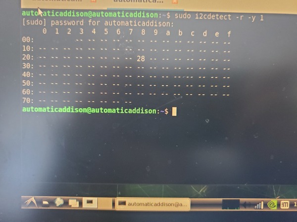
Type the following command to verify that you can see the BNO055.
sudo i2cdetect -r -y 1
Check that the bus of the BNO055 has an address of 0x28.
Install and Build the BNO055 ROS Package
Let’s get all the software set up.
Turn on your Jetson Nano.
Open a new terminal window.
Install the libi2c-dev library.
sudo apt-get update
sudo apt-get install libi2c-dev
Install the BNO055 ROS package.
cd ~/catkin_ws/src
Remove any existing package named ‘ros_imu_bno055’.
The microcontroller we will use is the Nvidia Jetson Nano, but you can also use an Ubuntu-enabled Raspberry Pi.
We will interface Arduino with ROS so we can publish the tick counts for the left wheel and right wheel to ROS topics. The name of this node will be tick_publisher.
Why Publish Wheel Encoder Tick Data
Tick data from wheel encoders helps us determine how much each wheel (both the left and right wheels) has rotated. Since we know the radius of each wheel, we can use the tick data and the wheel radius data to determine the distance traveled by each wheel. Here is the equation for that:
Distance a wheel has traveled = 2 * pi * radius of the wheel * (number of ticks / number of ticks per revolution)
Knowing the distance traveled by each wheel helps us determine where the robot is located in its environment relative to some starting location. This process is known as odometry.
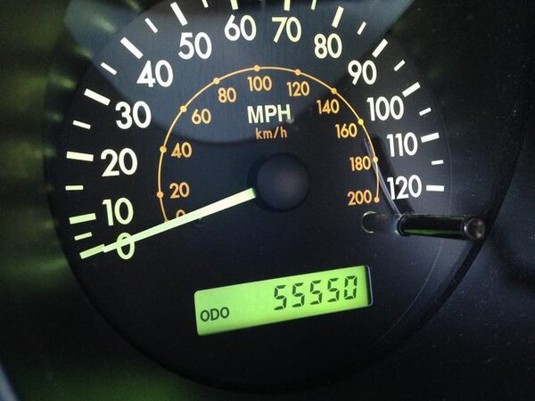
The first time you were exposed to the word “odometry” was likely when you began driving a car. Right behind your steering wheel is typically your odometer. The odometer of your car measures the distance traveled by the vehicle relative to some starting point where the car was first driven. Odometry in robotics works the same way.
A typical odometer on a car’s dashboard
Real-World Applications
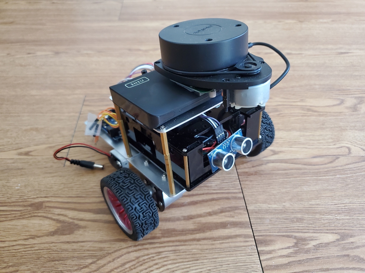
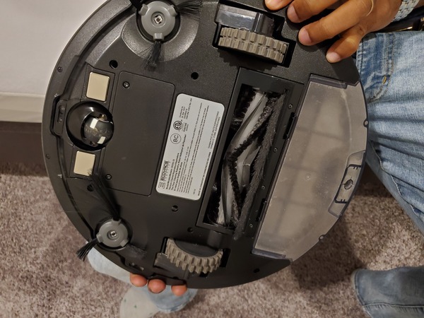
You can see that a robotic vacuum cleaner has the same two-wheeled differential drive setup as the robot I’m currently working with in this tutorial.
This project has a number of real-world applications:
Indoor Delivery Robots
Room Service Robots
Mapping of Underground Mines, Caves, and Hard-to-Reach Environments
Although not required at this stage, if you want your robot to perform autonomous navigation, eventually you will want to know how many ticks (i.e. pulses) are generated in one full revolution of your motor. To calculate this value for your motors, follow this tutorial. For the DC motors I’m using, there are 620 ticks per revolution.
You Will Need
Arduino Uno (Elegoo Uno works just fine and is cheaper than the regular Arduino)
Install Arduino on Your Jetson Nano
To get started, turn on your Jetson Nano.
Let’s download the Arduino IDE (you’ll have to download the Arduino IDE directly from the Arduino website if you are using Ubuntu on the Raspberry Pi).
Open a new terminal window, and type the following commands, one right after the other.
Open the IDE and go to File -> Preferences. Make a note of the Sketchbook location. Mine is:
/home/automaticaddison/Arduino
Quit the Arduino IDE.
Open a new terminal window, and go to the sketchbook location you noted above. I’ll type:
cd Arduino
Type the dir command to see the list of folders.
dir
Go to the libraries directory.
cd libraries
rm -rf ros_lib
Within that directory, run the following command to build the Arduino library that will be used by ROS (don’t leave out that period that comes at the end of the command):
rosrun rosserial_arduino make_libraries.py .
Type the dir command to see the list of folders. You should now see the ros_lib library.
dir
Make sure the Arduino IDE is closed. Now open it again.
Blink an LED on the Arduino Using ROS
In this example, Arduino is going to be considered a Subscriber node. It will subscribe to a topic called toggle_led. Publishing a message to that topic causes the LED to turn on. Publishing a message to the topic again causes the LED to turn off.
Go to File -> Examples -> ros_lib and open the Blink sketch.
Before the nh.initNode(); line, add the following code:
nh.getHardware()->setBaud(115200);
Now we need to upload the code to Arduino. Make sure your Arduino is plugged into the USB port on your Jetson Nano (or whatever microcontroller you are using).
Upload the code to your Arduino using the right arrow button in the upper left of your screen. When you upload the code, your Arduino should flicker a little bit.
Note: I created a new Arduino sketch and saved it to /home/automaticaddison/Documents as “blink_ros_arduino_test”. This is not required.
Quit the Arduino IDE.
Open a new terminal window and type:
roscore
In a new terminal window, launch the ROS serial server. This command is explained here on the ROS website. It is necessary to complete the integration between ROS and Arduino:
Now let’s turn on the LED by publishing a single empty message to the /toggle_led topic. Open a new terminal window and type:
rostopic pub toggle_led std_msgs/Empty --once
The LED on the Arduino should turn on.
Now press the Up arrow in the terminal and press ENTER to run this code again. You should see the LED turn off. You might also see a tiny yellow light blinking as well. Just ignore that one…you’re interested in the big yellow light that you’re able to turn off and on by publishing single messages to the /toggle_led topic.
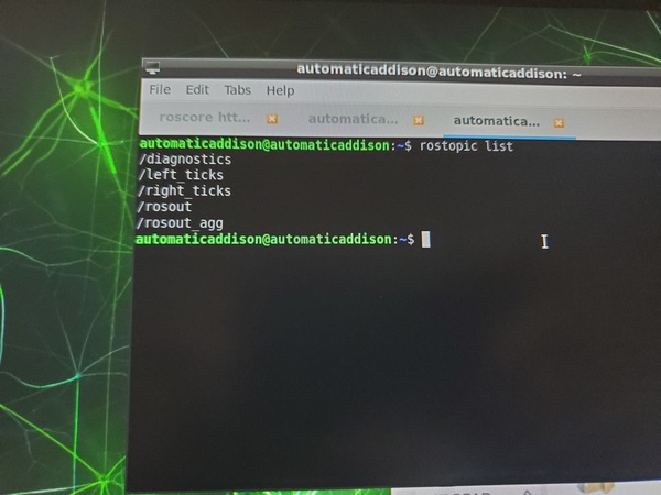
You can see the active topics by typing.
rostopic list
Another good example to check out is a publisher and subscriber. You can see this by going to:
File -> Examples -> ros_lib -> pubsub
This ROS node will blink an LED and publish a “Hello World” message to a topic named chatter.
That’s it! You have now seen how you can integrate Arduino with ROS. To turn off your Arduino, all you need to do is disconnect it after you shut down your Jetson Nano.
Create a Tick Publisher Node
Now we want to write a tick publisher node. This ROS node will publish the accumulated tick count for the left and right motors of the robot at regular intervals.
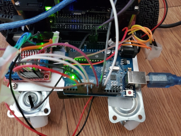
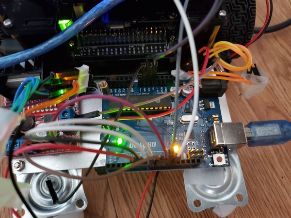
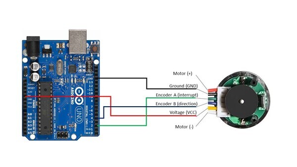
The Ground pin of the motor connects to GND of the Arduino. I’m using a 400-point solderless breadboard that I bought on Amazon.com to facilitate this connection.
Encoder A (sometimes labeled C1) of the motor connects to pin 2 of the Arduino. Pin 2 of the Arduino will record every time there is a rising digital signal from Encoder A.
Encoder B (sometimes labeled C2) of the motor connects to pin 4 of the Arduino. The signal that is read off pin 4 on the Arduino will determine if the motor is moving forward or in reverse. We’re not going to use this pin in this tutorial, but we will use it in a future tutorial.
The VCC pin of the motor connects to the 5V pin of the Arduino. This pin is responsible for providing power to the encoder.
For the right motor:
The Ground pin of the motor connects to GND of the Arduino.
Encoder A (sometimes labeled C1) of the motor connects to pin 3 of the Arduino. Pin 2 of the Arduino will record every time there is a rising digital signal from Encoder A.
Encoder B (sometimes labeled C2) of the motor connects to pin 11 of the Arduino. The signal that is read off pin 11 on the Arduino will determine if the motor is moving forward or in reverse.
The VCC pin of the motor connects to the 5V pin of the Arduino. This pin is responsible for providing power to the encoder.
Write the Code
Now we’re ready to calculate the accumulated ticks for each wheel.
Open the Arduino IDE, and write the following program. The name of my program is tick_counter.ino.
/*
 * Author: Automatic Addison
 * Website: https://automaticaddison.com
 * Description: Calculate the accumulated ticks for each wheel using the
 * built-in encoder (forward = positive; reverse = negative)
 */

// Encoder output to Arduino Interrupt pin. Tracks the tick count.
#define ENC_IN_LEFT_A 2
#define ENC_IN_RIGHT_A 3

// Other encoder output to Arduino to keep track of wheel direction
// Tracks the direction of rotation.
#define ENC_IN_LEFT_B 4
#define ENC_IN_RIGHT_B 11

// True = Forward; False = Reverse
boolean Direction_left = true;
boolean Direction_right = true;

// Minumum and maximum values for 16-bit integers
const int encoder_minimum = -32768;
const int encoder_maximum = 32767;

// Keep track of the number of wheel ticks
volatile int left_wheel_tick_count = 0;
volatile int right_wheel_tick_count = 0;

// One-second interval for measurements
int interval = 1000;
long previousMillis = 0;
long currentMillis = 0;

void setup() {

  // Open the serial port at 9600 bps
  Serial.begin(9600);

  // Set pin states of the encoder
  pinMode(ENC_IN_LEFT_A , INPUT_PULLUP);
  pinMode(ENC_IN_LEFT_B , INPUT);
  pinMode(ENC_IN_RIGHT_A , INPUT_PULLUP);
  pinMode(ENC_IN_RIGHT_B , INPUT);

  // Every time the pin goes high, this is a tick
  attachInterrupt(digitalPinToInterrupt(ENC_IN_LEFT_A), left_wheel_tick, RISING);
  attachInterrupt(digitalPinToInterrupt(ENC_IN_RIGHT_A), right_wheel_tick, RISING);
}

void loop() {

  // Record the time
  currentMillis = millis();

  // If one second has passed, print the number of ticks
  if (currentMillis - previousMillis > interval) {

    previousMillis = currentMillis;

    Serial.println("Number of Ticks: ");
    Serial.println(right_wheel_tick_count);
    Serial.println(left_wheel_tick_count);
    Serial.println();
  }
}

// Increment the number of ticks
void right_wheel_tick() {

  // Read the value for the encoder for the right wheel
  int val = digitalRead(ENC_IN_RIGHT_B);

  if(val == LOW) {
    Direction_right = false; // Reverse
  }
  else {
    Direction_right = true; // Forward
  }

  if (Direction_right) {

    if (right_wheel_tick_count == encoder_maximum) {
      right_wheel_tick_count = encoder_minimum;
    }
    else {
      right_wheel_tick_count++;
    }
  }
  else {
    if (right_wheel_tick_count == encoder_minimum) {
      right_wheel_tick_count = encoder_maximum;
    }
    else {
      right_wheel_tick_count--;
    }
  }
}

// Increment the number of ticks
void left_wheel_tick() {

  // Read the value for the encoder for the left wheel
  int val = digitalRead(ENC_IN_LEFT_B);

  if(val == LOW) {
    Direction_left = true; // Reverse
  }
  else {
    Direction_left = false; // Forward
  }

  if (Direction_left) {
    if (left_wheel_tick_count == encoder_maximum) {
      left_wheel_tick_count = encoder_minimum;
    }
    else {
      left_wheel_tick_count++;
    }
  }
  else {
    if (left_wheel_tick_count == encoder_minimum) {
      left_wheel_tick_count = encoder_maximum;
    }
    else {
      left_wheel_tick_count--;
    }
  }
}
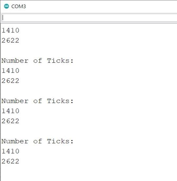
Upload the program to the Arduino.
If you open the serial monitor, you will see the accumulated tick count. Once the tick count gets outside the range of what a 16-bit integer can handle, it rolls over to either the minimum -32,768 or maximum 32,767 of the range.
Convert the Code to a ROS Node
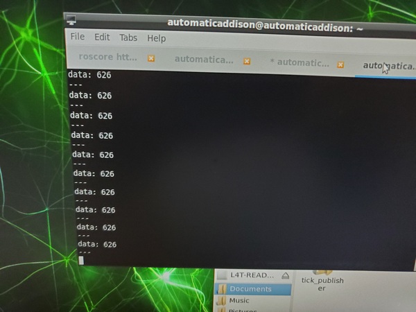
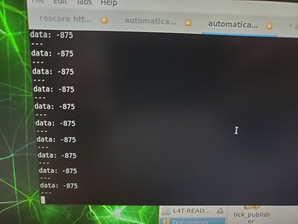
Now that we see how to print tick counts for the right and left motors, let’s convert the code from the previous section into a ROS node. We want our node to publish tick counts for the right and left wheels of the robot to ROS topics named right_ticks and left_ticks.
Open the Arduino IDE, and write the following program. The name of my program is tick_publisher.ino.
/*
 * Author: Automatic Addison
 * Website: https://automaticaddison.com
 * Description: ROS node that publishes the accumulated ticks for each wheel
 * (right_ticks and left_ticks topics) using the built-in encoder
 * (forward = positive; reverse = negative)
 */

#include <ros.h>
#include <std_msgs/Int16.h>

// Handles startup and shutdown of ROS
ros::NodeHandle nh;

// Encoder output to Arduino Interrupt pin. Tracks the tick count.
#define ENC_IN_LEFT_A 2
#define ENC_IN_RIGHT_A 3

// Other encoder output to Arduino to keep track of wheel direction
// Tracks the direction of rotation.
#define ENC_IN_LEFT_B 4
#define ENC_IN_RIGHT_B 11

// True = Forward; False = Reverse
boolean Direction_left = true;
boolean Direction_right = true;

// Minumum and maximum values for 16-bit integers
const int encoder_minimum = -32768;
const int encoder_maximum = 32767;

// Keep track of the number of wheel ticks
std_msgs::Int16 right_wheel_tick_count;
ros::Publisher rightPub("right_ticks", &right_wheel_tick_count);

std_msgs::Int16 left_wheel_tick_count;
ros::Publisher leftPub("left_ticks", &left_wheel_tick_count);

// 100ms interval for measurements
const int interval = 100;
long previousMillis = 0;
long currentMillis = 0;

// Increment the number of ticks
void right_wheel_tick() {

  // Read the value for the encoder for the right wheel
  int val = digitalRead(ENC_IN_RIGHT_B);

  if(val == LOW) {
    Direction_right = false; // Reverse
  }
  else {
    Direction_right = true; // Forward
  }

  if (Direction_right) {

    if (right_wheel_tick_count.data == encoder_maximum) {
      right_wheel_tick_count.data = encoder_minimum;
    }
    else {
      right_wheel_tick_count.data++;
    }
  }
  else {
    if (right_wheel_tick_count.data == encoder_minimum) {
      right_wheel_tick_count.data = encoder_maximum;
    }
    else {
      right_wheel_tick_count.data--;
    }
  }
}

// Increment the number of ticks
void left_wheel_tick() {

  // Read the value for the encoder for the left wheel
  int val = digitalRead(ENC_IN_LEFT_B);

  if(val == LOW) {
    Direction_left = true; // Reverse
  }
  else {
    Direction_left = false; // Forward
  }

  if (Direction_left) {
    if (left_wheel_tick_count.data == encoder_maximum) {
      left_wheel_tick_count.data = encoder_minimum;
    }
    else {
      left_wheel_tick_count.data++;
    }
  }
  else {
    if (left_wheel_tick_count.data == encoder_minimum) {
      left_wheel_tick_count.data = encoder_maximum;
    }
    else {
      left_wheel_tick_count.data--;
    }
  }
}

void setup() {

  // Set pin states of the encoder
  pinMode(ENC_IN_LEFT_A , INPUT_PULLUP);
  pinMode(ENC_IN_LEFT_B , INPUT);
  pinMode(ENC_IN_RIGHT_A , INPUT_PULLUP);
  pinMode(ENC_IN_RIGHT_B , INPUT);

  // Every time the pin goes high, this is a tick
  attachInterrupt(digitalPinToInterrupt(ENC_IN_LEFT_A), left_wheel_tick, RISING);
  attachInterrupt(digitalPinToInterrupt(ENC_IN_RIGHT_A), right_wheel_tick, RISING);

  // ROS Setup
  nh.getHardware()->setBaud(115200);
  nh.initNode();
  nh.advertise(rightPub);
  nh.advertise(leftPub);
}

void loop() {

  // Record the time
  currentMillis = millis();

  // If 100ms have passed, print the number of ticks
  if (currentMillis - previousMillis > interval) {

    previousMillis = currentMillis;

    rightPub.publish( &right_wheel_tick_count );
    leftPub.publish( &left_wheel_tick_count );
    nh.spinOnce();
  }
}
Upload the code to your Arduino using the right arrow button in the upper left of your screen.
Quit the Arduino IDE.
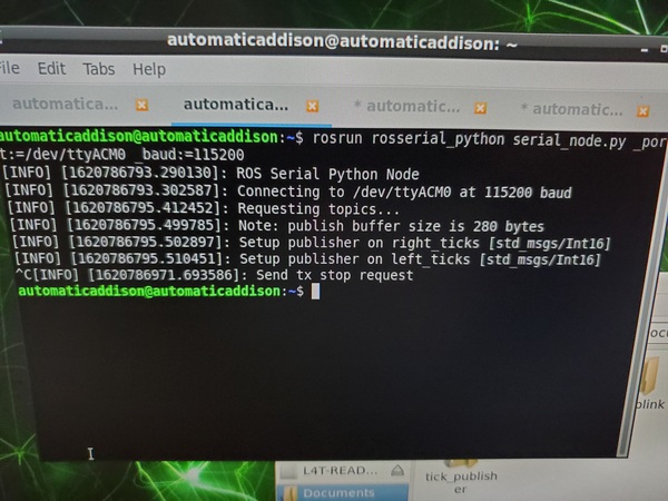
Run the Tick Publisher
Open a new terminal window and type:
roscore
In a new terminal window, launch the ROS serial server.