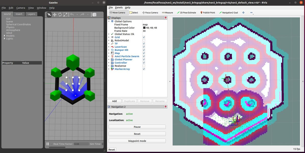
In this tutorial, we will explore Navigation2 (Nav2), which is a collection of tools for ROS 2 that enable a robot to go from point A to point B safely. We will also take a look at a SLAM demo with a robot named Turtlebot 3. Here will be our final output:
Real-World Applications
Navigation is one of the most important tasks for a mobile robot. Navigation is about enabling a mobile robot to move from one location to another without running into any obstacles.
In order to navigate properly, a robot needs to have a map (mapping), know where it is located (localization), and have a plan for getting from point A to point B (path planning).
***Note: The official instructions for installing Nav2 arehere. Please check out that link to get the latest instructions. The steps below are valid as of the date of this blog post and will likely be different by the time you read this.***
To install Nav2, open a new terminal window, and type the following commands:
sudo apt install ros-foxy-navigation2
Type Y and then Enter to continue.
sudo apt install ros-foxy-nav2-bringup
Type Y and then Enter to continue.
Install the Turtlebot 3 example.
Open a new terminal window, and type:
sudo apt install ros-foxy-turtlebot3*
sudo apt install ros-foxy-nav2-simple-commander
If you want to build from the source (i.e. get the ROS2 navigation packages directly from GitHub), open a new terminal window, and type the following commands. One right after the other.
Your computer might say something like “executing command [sudo ……”. That is fine. Just wait, and let your system finish doing what it is doing.
colcon build --symlink-install
It took a while to install Nav2 on my machine. Just be patient.
You noticed that if we install Nav2 from the source, we also needed to install it using the Ubuntu package manager first. The reason we had to do both is that the Ubuntu package manager installs some non-ROS dependencies that are necessary for Nav2 to build from the source.
Building Nav2 from the source (using the Github clone command we did above) enables us to customize the packages in Nav2 to our liking (e.g. add new plugins, messages, etc.) that won’t get overwritten during a system upgrade (i.e. sudo apt-get upgrade)
When Nav2 is finished installing, open your bash file.
gedit ~/.bashrc
Add these lines to the bottom of the file. You can get the latest information on what to add on this link.
Build it again, just to make sure everything is in order
colcon build
Test Your Installation
Now test your installation.
Open a new terminal window.
cd ~/nav2_ws
ros2 launch nav2_bringup tb3_simulation_launch.py
rviz2 will open.
Gazebo will also open, but it may take a while.
Move the Robot From Point A to Point B
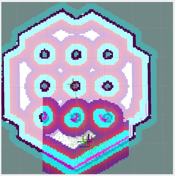
Now go to the rviz2 screen.
Set the initial pose of the robot by clicking the “2D Pose Estimate” on top of the rviz2 screen. Then click on the map in the estimated position where the robot is in Gazebo.
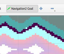
Set a goal for the robot to move to. Click “Navigation2 Goal” button and choose a destination. The wheeled robot will move to the goal destination.
In the bottom left of the screen, you can Pause and Reset.
Press CTRL + C on all terminal windows to close down the programs.
Install the SLAM Toolbox
Now that we know how to navigate the robot from point A to point B with a prebuilt map, let’s see how we can navigate the robot while mapping. This process is known as Simultaneous localization and mapping (SLAM).
Open a new terminal window. Type this command:
sudo apt install ros-foxy-slam-toolbox
Launch the SLAM launch file. Open a new terminal window, and type:
cd ~/nav2_ws
ros2 launch nav2_bringup slam_launch.py
Now launch the robot.
ros2 launch nav2_bringup tb3_simulation_launch.py
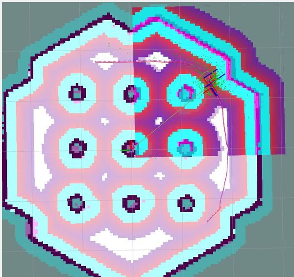
Click the 2D Pose Estimate button and click on the rviz screen an estimate position where the robot is in Gazebo.
Then click the Navigation2 Goal button and click on an area of rviz where you want the robot to go.
Press CTRL+C in all terminals to shut everything down.
Here is another command you can run. This command launches Turtlebot3 and the SLAM package in a single command.
In this tutorial, we will build a program that can determine the orientation of an object (i.e. rotation angle in degrees) using the popular computer vision library OpenCV.
Real-World Applications
One of the most common real-world use cases of the program we will develop in this tutorial is when you want to develop a pick and place system for robotic arms. Determining the orientation of an object on a conveyor belt is key to determining the appropriate way to grasp the object, pick it up, and place it in another location.
Before we get started, let’s make sure we have all the software packages installed. Check to see if you have OpenCV installed on your machine. If you are using Anaconda, you can type:
conda install -c conda-forge opencv
Alternatively, you can type:
pip install opencv-python
Install Numpy, the scientific computing library.
pip install numpy
Find an Image File
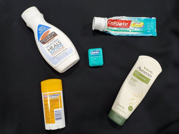
Find an image. My input image is 1200 pixels in width and 900 pixels in height. The filename of my input image is input_img.jpg.
Write the Code
Here is the code. It accepts an image named input_img.jpg and outputs an annotated image named output_img.jpg. Pieces of the code pull from the official OpenCV implementation.
import cv2 as cv
from math import atan2, cos, sin, sqrt, pi
import numpy as np

def drawAxis(img, p_, q_, color, scale):
  p = list(p_)
  q = list(q_)

  ## [visualization1]
  angle = atan2(p[1] - q[1], p[0] - q[0]) # angle in radians
  hypotenuse = sqrt((p[1] - q[1]) * (p[1] - q[1]) + (p[0] - q[0]) * (p[0] - q[0]))

  # Here we lengthen the arrow by a factor of scale
  q[0] = p[0] - scale * hypotenuse * cos(angle)
  q[1] = p[1] - scale * hypotenuse * sin(angle)
  cv.line(img, (int(p[0]), int(p[1])), (int(q[0]), int(q[1])), color, 3, cv.LINE_AA)

  # create the arrow hooks
  p[0] = q[0] + 9 * cos(angle + pi / 4)
  p[1] = q[1] + 9 * sin(angle + pi / 4)
  cv.line(img, (int(p[0]), int(p[1])), (int(q[0]), int(q[1])), color, 3, cv.LINE_AA)

  p[0] = q[0] + 9 * cos(angle - pi / 4)
  p[1] = q[1] + 9 * sin(angle - pi / 4)
  cv.line(img, (int(p[0]), int(p[1])), (int(q[0]), int(q[1])), color, 3, cv.LINE_AA)
  ## [visualization1]

def getOrientation(pts, img):
  ## [pca]
  # Construct a buffer used by the pca analysis
  sz = len(pts)
  data_pts = np.empty((sz, 2), dtype=np.float64)
  for i in range(data_pts.shape[0]):
    data_pts[i,0] = pts[i,0,0]
    data_pts[i,1] = pts[i,0,1]

  # Perform PCA analysis
  mean = np.empty((0))
  mean, eigenvectors, eigenvalues = cv.PCACompute2(data_pts, mean)

  # Store the center of the object
  cntr = (int(mean[0,0]), int(mean[0,1]))
  ## [pca]

  ## [visualization]
  # Draw the principal components
  cv.circle(img, cntr, 3, (255, 0, 255), 2)
  p1 = (cntr[0] + 0.02 * eigenvectors[0,0] * eigenvalues[0,0], cntr[1] + 0.02 * eigenvectors[0,1] * eigenvalues[0,0])
  p2 = (cntr[0] - 0.02 * eigenvectors[1,0] * eigenvalues[1,0], cntr[1] - 0.02 * eigenvectors[1,1] * eigenvalues[1,0])
  drawAxis(img, cntr, p1, (255, 255, 0), 1)
  drawAxis(img, cntr, p2, (0, 0, 255), 5)

  angle = atan2(eigenvectors[0,1], eigenvectors[0,0]) # orientation in radians
  ## [visualization]

  # Label with the rotation angle
  label = "  Rotation Angle: " + str(-int(np.rad2deg(angle)) - 90) + " degrees"
  textbox = cv.rectangle(img, (cntr[0], cntr[1]-25), (cntr[0] + 250, cntr[1] + 10), (255,255,255), -1)
  cv.putText(img, label, (cntr[0], cntr[1]), cv.FONT_HERSHEY_SIMPLEX, 0.5, (0,0,0), 1, cv.LINE_AA)

  return angle

# Load the image
img = cv.imread("input_img.jpg")

# Was the image there?
if img is None:
  print("Error: File not found")
  exit(0)

cv.imshow('Input Image', img)

# Convert image to grayscale
gray = cv.cvtColor(img, cv.COLOR_BGR2GRAY)

# Convert image to binary
_, bw = cv.threshold(gray, 50, 255, cv.THRESH_BINARY | cv.THRESH_OTSU)

# Find all the contours in the thresholded image
contours, _ = cv.findContours(bw, cv.RETR_LIST, cv.CHAIN_APPROX_NONE)

for i, c in enumerate(contours):

  # Calculate the area of each contour
  area = cv.contourArea(c)

  # Ignore contours that are too small or too large
  if area < 3700 or 100000 < area:
    continue

  # Draw each contour only for visualisation purposes
  cv.drawContours(img, contours, i, (0, 0, 255), 2)

  # Find the orientation of each shape
  getOrientation(c, img)

cv.imshow('Output Image', img)
cv.waitKey(0)
cv.destroyAllWindows()

# Save the output image to the current directory
cv.imwrite("output_img.jpg", img)
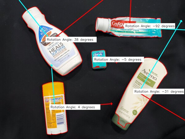
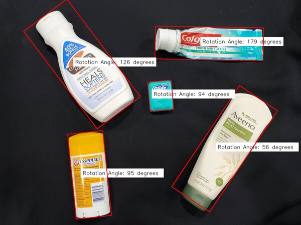
Output Image
Here is the result:
Understanding the Rotation Axes
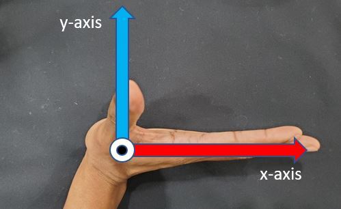
The positive x-axis of each object is the red line. The positive y-axis of each object is the blue line.
The global positive x-axis goes from left to right horizontally across the image. The global positive z-axis points out of this page. The global positive y-axis points from the bottom of the image to the top of the image vertically.
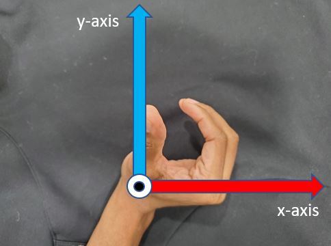
Using the right-hand rule to measure rotation, you stick your four fingers out straight (index finger to pinky finger) in the direction of the global positive x-axis.
You then rotate your four fingers 90 degrees counterclockwise. Your fingertips point towards the positive y-axis, and your thumb points out of this page towards the positive z-axis.
Calculate an Orientation Between 0 and 180 Degrees
If we want to calculate the orientation of an object and make sure that the result is always between 0 and 180 degrees, we can use this code:
# This programs calculates the orientation of an object.
# The input is an image, and the output is an annotated image
# with the angle of otientation for each object (0 to 180 degrees)

import cv2 as cv
from math import atan2, cos, sin, sqrt, pi
import numpy as np

# Load the image
img = cv.imread("input_img.jpg")

# Was the image there?
if img is None:
  print("Error: File not found")
  exit(0)

cv.imshow('Input Image', img)

# Convert image to grayscale
gray = cv.cvtColor(img, cv.COLOR_BGR2GRAY)

# Convert image to binary
_, bw = cv.threshold(gray, 50, 255, cv.THRESH_BINARY | cv.THRESH_OTSU)

# Find all the contours in the thresholded image
contours, _ = cv.findContours(bw, cv.RETR_LIST, cv.CHAIN_APPROX_NONE)

for i, c in enumerate(contours):

  # Calculate the area of each contour
  area = cv.contourArea(c)

  # Ignore contours that are too small or too large
  if area < 3700 or 100000 < area:
    continue

  # cv.minAreaRect returns:
  # (center(x, y), (width, height), angle of rotation) = cv2.minAreaRect(c)
  rect = cv.minAreaRect(c)
  box = cv.boxPoints(rect)
  box = np.int0(box)

  # Retrieve the key parameters of the rotated bounding box
  center = (int(rect[0][0]),int(rect[0][1]))
  width = int(rect[1][0])
  height = int(rect[1][1])
  angle = int(rect[2])


  if width < height:
    angle = 90 - angle
  else:
    angle = -angle

  label = "  Rotation Angle: " + str(angle) + " degrees"
  textbox = cv.rectangle(img, (center[0]-35, center[1]-25),
    (center[0] + 295, center[1] + 10), (255,255,255), -1)
  cv.putText(img, label, (center[0]-50, center[1]),
    cv.FONT_HERSHEY_SIMPLEX, 0.7, (0,0,0), 1, cv.LINE_AA)
  cv.drawContours(img,[box],0,(0,0,255),2)

cv.imshow('Output Image', img)
cv.waitKey(0)
cv.destroyAllWindows()

# Save the output image to the current directory
cv.imwrite("min_area_rec_output.jpg", img)
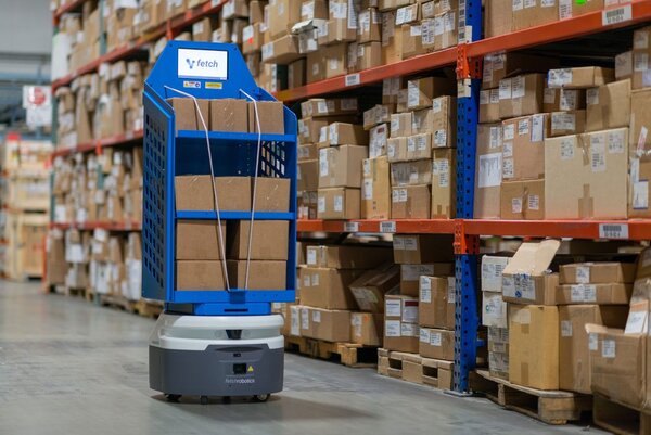
In this tutorial, we will learn how to create an autonomous mobile robot from scratch using Gazebo. We will learn how to create an environment for the robot to move around in. We will also learn how to integrate ROS 2 and Gazebo so that we can control the robot by sending it velocity commands. Here is what you will build:
The type of robot we will create is an autonomous differential drive mobile warehouse robot. We will build the entire SDF file (Simulation Description Format) from scratch. Our simulated robot will be similar to the one below created by Fetch Robotics, a mobile robotics company based in Silicon Valley in California.
Credit: Fetch Robotics
Real-World Applications
Mobile warehouse robots are used extensively in the industry. Amazon uses these robots to transport shelves around their fulfillment centers to make sure customers receive their goods as quickly as possible.
Roboticists like to simulate robots before building them in order to test out different algorithms. You can imagine the cost of making mistakes with a physical robot can be high (e.g. crashing a mobile robot into a wall at high speed means lost money).
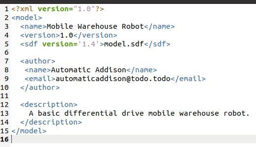
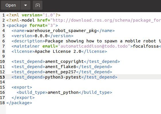
Modify this model.config file. You can see this file contains fields for the name of the robot, the version, the author (that’s you), your e-mail address, and a description of the robot.
Save the file, and then close it.
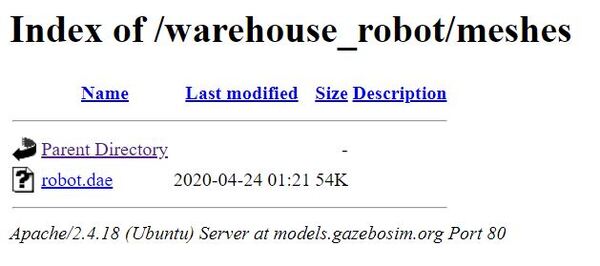
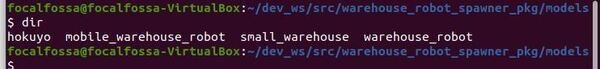
Download the Mesh Files
Mesh files help make your robots look more realistic than just using basic shapes.
Download the warehouse robot mesh file. The warehouse robot mesh file is at this link. To download it, you need to open a new terminal window, and type the following commands:
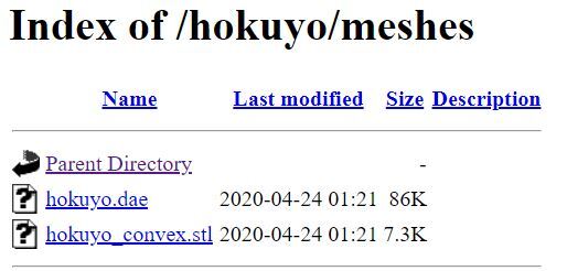
You can see that the dae file we need for the mesh is hokuyo.dae. You will see this filename inside the sdf file we’ll create in the next section.
Create Model.sdf
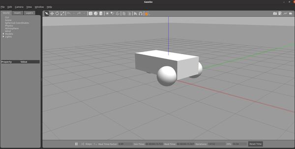
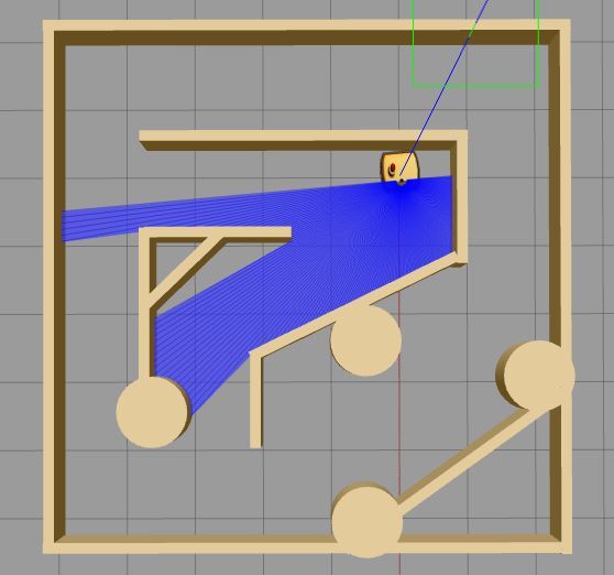
Now, let’s create an SDF (Simulation Description Format) file. This file will contain the tags that are needed to create an instance of the mobile_warehouse_robot model. Our robot will have three wheels: two wheels in the front and a caster wheel in the back. On top of the robot, we will mount the laser range finder that will send out beams in a 180-degree radius in order to detect obstacles.
Here is my sdf file. You can copy and paste those lines inside your sdf file.
Save the file and close it to return to the terminal.
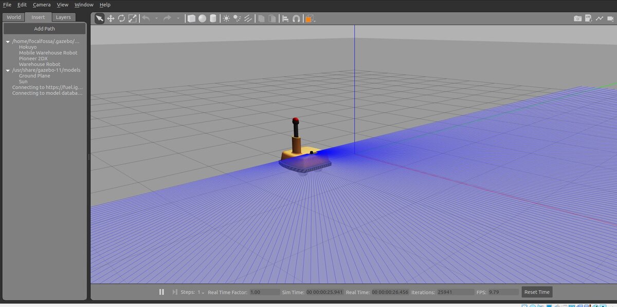
Test Your Robot
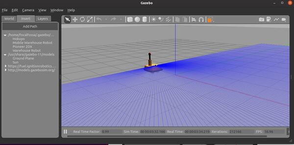
Now let’s run Gazebo so that we can see our model. Type the following command:
gazebo
On the left-hand side, click the “Insert” tab.
On the left panel, click “Mobile Warehouse Robot”. You should see a warehouse robot. You can place it wherever you want by clicking inside the environment.
Click on your model to select it.
Go back to the terminal window, and type CTRL + C to close Gazebo.
Integrate ROS 2 and Gazebo
Install gazebo_ros_pkgs
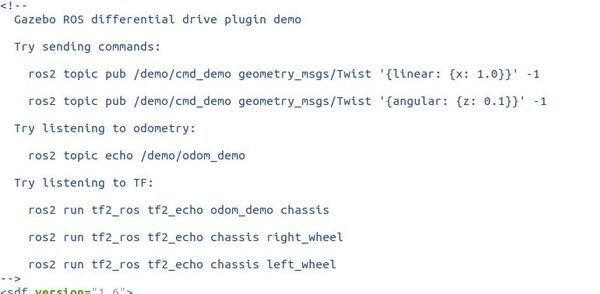
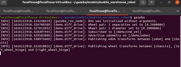
Open a new terminal window, and install the packages that will enable you to use ROS 2 to interface with Gazebo. We need to install a whole bunch of stuff, including the differential drive plugin that will enable us to control the speed of our robot using ROS 2 commands.
You will see the robot bob up and down for a bit and then stabilize as it moves forward. The bobbing action is due to the uneven weight caused by the beacon and the laser range finder on top of the robot.
Feel free to tweak the parameters (radii, positioning of the wheels, etc.) to see if you get smoother performance.
Build a Warehouse
Now we are going to build a warehouse for our robot to move around in.
Create Model.config
Create a folder for the model.
mkdir -p ~/.gazebo/models/small_warehouse
Create a model config file. This file will contain a description of the model.
Add these lines to the file, and then Save. You can see this file contains fields for the name of the robot, the version, the author (that’s you), your email address, and a description of the robot.
Save the file, and then close it.
Create Model.sdf
Now, let’s create an SDF (Simulation Description Format) file. This file will contain the tags that are needed to create an instance of the small_warehouse model.
gedit ~/.gazebo/models/small_warehouse/model.sdf
Write these lines inside the sdf file. You can see how many lines of code there are. It takes a lot of code to create even the simplest of models in Gazebo.
Save the file and close it to return to the terminal.
Note, you can also create your own warehouse using Gazebo’s drag and drop interface. Gazebo enables you to add pieces to the world and then save the world as an sdf file.
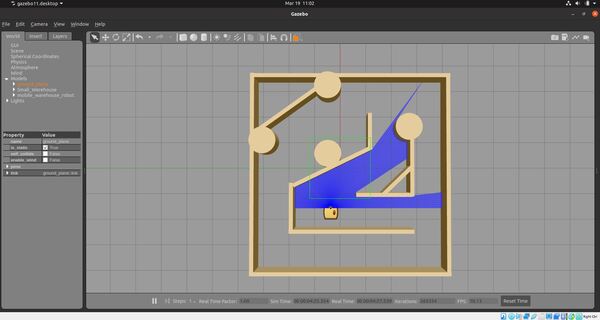
Test Your Warehouse
Now let’s run Gazebo so that we can see our model. Type the following command:
gazebo
On the left-hand side, click the “Insert” tab.
On the left panel, click “Small Warehouse”. You should see a warehouse robot. You can place it wherever you want by clicking inside the environment.
Click on your model to select it. I have also added our mobile warehouse robot to the scene.
Go back to the terminal window, and type CTRL + C to close Gazebo.
Launch Your Robot and Warehouse Using ROS 2
Now that we have created our robot and our warehouse, let’s see how we can launch these pieces using ROS 2.
Open a new terminal window, and navigate to the src directory of your workspace (the name of my workspace is dev_ws, but your workspace might have a different name):
cd ~/dev_ws/src
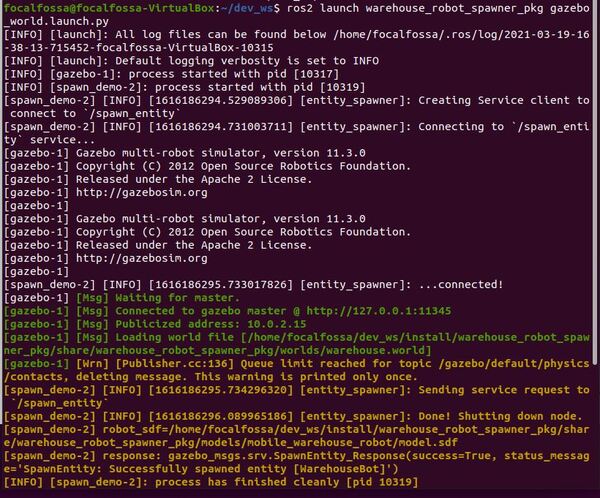
Now let’s create a package named warehouse_robot_spawner_pkg.
# Copyright 2019 Open Source Robotics Foundation, Inc.
#
# Licensed under the Apache License, Version 2.0 (the "License");
# you may not use this file except in compliance with the License.
# You may obtain a copy of the License at
#
#     http://www.apache.org/licenses/LICENSE-2.0
#
# Unless required by applicable law or agreed to in writing, software
# distributed under the License is distributed on an "AS IS" BASIS,
# WITHOUT WARRANTIES OR CONDITIONS OF ANY KIND, either express or implied.
# See the License for the specific language governing permissions and
# limitations under the License.

"""
Demo for spawn_entity.
Launches Gazebo and spawns a model
"""
# A bunch of software packages that are needed to launch ROS2
import os
from launch import LaunchDescription
from launch.actions import IncludeLaunchDescription
from launch.launch_description_sources import PythonLaunchDescriptionSource
from launch.substitutions import ThisLaunchFileDir,LaunchConfiguration
from launch_ros.actions import Node
from launch.actions import ExecuteProcess
from ament_index_python.packages import get_package_share_directory

def generate_launch_description():
    use_sim_time = LaunchConfiguration('use_sim_time', default='True')
    world_file_name = 'warehouse.world'
    pkg_dir = get_package_share_directory('warehouse_robot_spawner_pkg')

    os.environ["GAZEBO_MODEL_PATH"] = os.path.join(pkg_dir, 'models')

    world = os.path.join(pkg_dir, 'worlds', world_file_name)
    launch_file_dir = os.path.join(pkg_dir, 'launch')

    gazebo = ExecuteProcess(
            cmd=['gazebo', '--verbose', world, '-s', 'libgazebo_ros_init.so',
            '-s', 'libgazebo_ros_factory.so'],
            output='screen')

    #GAZEBO_MODEL_PATH has to be correctly set for Gazebo to be able to find the model
    #spawn_entity = Node(package='gazebo_ros', node_executable='spawn_entity.py',
    #                    arguments=['-entity', 'demo', 'x', 'y', 'z'],
    #                    output='screen')
    spawn_entity = Node(package='warehouse_robot_spawner_pkg', executable='spawn_demo',
                        arguments=['WarehouseBot', 'demo', '-1.5', '-4.0', '0.0'],
                        output='screen')

    return LaunchDescription([
        gazebo,
        spawn_entity,
    ])
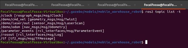
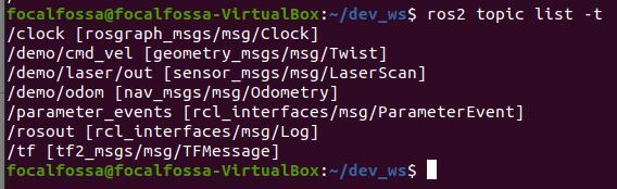
Now we need to create two ROS 2 nodes. One node will be responsible for estimating the current state of the robot in the world (i.e. position and orientation). The other node will send velocity commands to the robot.
Move inside the warehouse_robot_controller_pkg folder.
cd ~/dev_ws/src/warehouse_robot_controller_pkg/warehouse_robot_controller_pkg/
Open a new Python file named robot_estimator.py. Don’t be intimidated by how much code there is. Just take it one section at a time. I included a lot of comments so that you know what is going on.
gedit robot_estimator.py
Write the following code inside the file.
# Author: Addison Sears-Collins
# Date: March 19, 2021
# ROS Version: ROS 2 Foxy Fitzroy

# Python math library
import math

# ROS client library for Python
import rclpy

# Used to create nodes
from rclpy.node import Node

# Twist is linear and angular velocity
from geometry_msgs.msg import Twist

# Position, orientation, linear velocity, angular velocity
from nav_msgs.msg import Odometry

# Handles laser distance scan to detect obstacles
from sensor_msgs.msg import LaserScan

# Used for laser scan
from rclpy.qos import qos_profile_sensor_data

# Enable use of std_msgs/Float64MultiArray message
from std_msgs.msg import Float64MultiArray

# Scientific computing library for Python
import numpy as np

class Estimator(Node):
  """
  Class constructor to set up the node
  """
  def __init__(self):

    ############## INITIALIZE ROS PUBLISHERS AND SUBSCRIBERS ######
    super().__init__('Estimator')

    # Create a subscriber
    # This node subscribes to messages of type
    # nav_msgs/Odometry (i.e. position and orientation of the robot)
    self.odom_subscriber = self.create_subscription(
                           Odometry,
                           '/demo/odom',
                           self.odom_callback,
                           10)

    # Create a subscriber
    # This node subscribes to messages of type
    # geometry_msgs/Twist.msg. We are listening to the velocity commands here.
    # The maximum number of queued messages is 10.
    self.velocity_subscriber = self.create_subscription(
                               Twist,
                               '/demo/cmd_vel',
                               self.velocity_callback,
                               10)

    # Create a publisher
    # This node publishes the estimated position (x, y, yaw)
    # The type of message is std_msgs/Float64MultiArray
    self.publisher_state_est = self.create_publisher(
                               Float64MultiArray,
                               '/demo/state_est',
                               10)

  def odom_callback(self, msg):
    """
    Receive the odometry information containing the position and orientation
    of the robot in the global reference frame.
    The position is x, y, z.
    The orientation is a x,y,z,w quaternion.
    """
    roll, pitch, yaw = self.euler_from_quaternion(
      msg.pose.pose.orientation.x,
      msg.pose.pose.orientation.y,
      msg.pose.pose.orientation.z,
      msg.pose.pose.orientation.w)

    obs_state_vector_x_y_yaw = [msg.pose.pose.position.x,msg.pose.pose.position.y,yaw]

    # Publish the estimated state (x position, y position, yaw angle)
    self.publish_estimated_state(obs_state_vector_x_y_yaw)

  def publish_estimated_state(self, state_vector_x_y_yaw):
    """
    Publish the estimated pose (position and orientation) of the
    robot to the '/demo/state_est' topic.
    :param: state_vector_x_y_yaw [x, y, yaw]
    x is in meters, y is in meters, yaw is in radians
    """
    msg = Float64MultiArray()
    msg.data = state_vector_x_y_yaw
    self.publisher_state_est.publish(msg)

  def euler_from_quaternion(self, x, y, z, w):
    """
    Convert a quaternion into euler angles (roll, pitch, yaw)
    roll is rotation around x in radians (counterclockwise)
    pitch is rotation around y in radians (counterclockwise)
    yaw is rotation around z in radians (counterclockwise)
    """
    t0 = +2.0 * (w * x + y * z)
    t1 = +1.0 - 2.0 * (x * x + y * y)
    roll_x = math.atan2(t0, t1)

    t2 = +2.0 * (w * y - z * x)
    t2 = +1.0 if t2 > +1.0 else t2
    t2 = -1.0 if t2 < -1.0 else t2
    pitch_y = math.asin(t2)

    t3 = +2.0 * (w * z + x * y)
    t4 = +1.0 - 2.0 * (y * y + z * z)
    yaw_z = math.atan2(t3, t4)

    return roll_x, pitch_y, yaw_z # in radians

  def velocity_callback(self, msg):
    """
    Listen to the velocity commands (linear forward velocity
    in the x direction in the robot's reference frame and
    angular velocity (yaw rate) around the robot's z-axis.
    [v,yaw_rate]
    [meters/second, radians/second]
    """
    # Forward velocity in the robot's reference frame
    v = msg.linear.x

    # Angular velocity around the robot's z axis
    yaw_rate = msg.angular.z

def main(args=None):
    """
    Entry point for the program.
    """
    # Initialize rclpy library
    rclpy.init(args=args)

    # Create the node
    estimator = Estimator()

    # Spin the node so the callback function is called.
    # Pull messages from any topics this node is subscribed to.
    # Publish any pending messages to the topics.
    rclpy.spin(estimator)

    # Destroy the node explicitly
    # (optional - otherwise it will be done automatically
    # when the garbage collector destroys the node object)
    estimator.destroy_node()

    # Shutdown the ROS client library for Python
    rclpy.shutdown()

if __name__ == '__main__':
    main()
Save and close the Python program.
Open a new Python file named robot_controller.py.
gedit robot_controller.py
Write the following code inside the file.
# Author: Addison Sears-Collins
# Date: March 19, 2021
# ROS Version: ROS 2 Foxy Fitzroy

############## IMPORT LIBRARIES #################
# Python math library
import math

# ROS client library for Python
import rclpy

# Enables pauses in the execution of code
from time import sleep

# Used to create nodes
from rclpy.node import Node

# Enables the use of the string message type
from std_msgs.msg import String

# Twist is linear and angular velocity
from geometry_msgs.msg import Twist

# Handles LaserScan messages to sense distance to obstacles (i.e. walls)
from sensor_msgs.msg import LaserScan

# Handle Pose messages
from geometry_msgs.msg import Pose

# Handle float64 arrays
from std_msgs.msg import Float64MultiArray

# Handles quality of service for LaserScan data
from rclpy.qos import qos_profile_sensor_data

# Scientific computing library
import numpy as np

class Controller(Node):
  """
  Create a Controller class, which is a subclass of the Node
  class for ROS2.
  """
  def __init__(self):
    """
    Class constructor to set up the node
    """
    ##################### ROS SETUP ####################################################
    # Initiate the Node class's constructor and give it a name
    super().__init__('Controller')

    # Create a subscriber
    # This node subscribes to messages of type Float64MultiArray
    # over a topic named: /demo/state_est
    # The message represents the current estimated state:
    #   [x, y, yaw]
    # The callback function is called as soon as a message
    # is received.
    # The maximum number of queued messages is 10.
    self.subscription = self.create_subscription(
                        Float64MultiArray,
                        '/demo/state_est',
                        self.state_estimate_callback,
                        10)
    self.subscription  # prevent unused variable warning

    # Create a subscriber
    # This node subscribes to messages of type
    # sensor_msgs/LaserScan
    self.scan_subscriber = self.create_subscription(
                           LaserScan,
                           '/demo/laser/out',
                           self.scan_callback,
                           qos_profile=qos_profile_sensor_data)

    # Create a publisher
    # This node publishes the desired linear and angular velocity of the robot (in the
    # robot chassis coordinate frame) to the /demo/cmd_vel topic. Using the diff_drive
    # plugin enables the robot model to read this /demo/cmd_vel topic and execute
    # the motion accordingly.
    self.publisher_ = self.create_publisher(
                      Twist,
                      '/demo/cmd_vel',
                      10)

    # Initialize the LaserScan sensor readings to some large value
    # Values are in meters.
    self.left_dist = 999999.9 # Left
    self.leftfront_dist = 999999.9 # Left-front
    self.front_dist = 999999.9 # Front
    self.rightfront_dist = 999999.9 # Right-front
    self.right_dist = 999999.9 # Right

    ################### ROBOT CONTROL PARAMETERS ##################
    # Maximum forward speed of the robot in meters per second
    # Any faster than this and the robot risks falling over.
    self.forward_speed = 0.025

    # Current position and orientation of the robot in the global
    # reference frame
    self.current_x = 0.0
    self.current_y = 0.0
    self.current_yaw = 0.0

    ############# WALL FOLLOWING PARAMETERS #######################
    # Finite states for the wall following mode
    #  "turn left": Robot turns towards the left
    #  "search for wall": Robot tries to locate the wall
    #  "follow wall": Robot moves parallel to the wall
    self.wall_following_state = "turn left"

    # Set turning speeds (to the left) in rad/s
    # These values were determined by trial and error.
    self.turning_speed_wf_fast = 3.0  # Fast turn
    self.turning_speed_wf_slow = 0.05 # Slow turn

    # Wall following distance threshold.
    # We want to try to keep within this distance from the wall.
    self.dist_thresh_wf = 0.50 # in meters

    # We don't want to get too close to the wall though.
    self.dist_too_close_to_wall = 0.19 # in meters

  def state_estimate_callback(self, msg):
    """
    Extract the position and orientation data.
    This callback is called each time
    a new message is received on the '/demo/state_est' topic
    """
    # Update the current estimated state in the global reference frame
    curr_state = msg.data
    self.current_x = curr_state[0]
    self.current_y = curr_state[1]
    self.current_yaw = curr_state[2]

    # Command the robot to keep following the wall
    self.follow_wall()

  def scan_callback(self, msg):
    """
    This method gets called every time a LaserScan message is
    received on the '/demo/laser/out' topic
    """
    # Read the laser scan data that indicates distances
    # to obstacles (e.g. wall) in meters and extract
    # 5 distinct laser readings to work with.
    # Each reading is separated by 45 degrees.
    # Assumes 181 laser readings, separated by 1 degree.
    # (e.g. -90 degrees to 90 degrees....0 to 180 degrees)

    #number_of_laser_beams = str(len(msg.ranges))
    self.left_dist = msg.ranges[180]
    self.leftfront_dist = msg.ranges[135]
    self.front_dist = msg.ranges[90]
    self.rightfront_dist = msg.ranges[45]
    self.right_dist = msg.ranges[0]

  def follow_wall(self):
    """
    This method causes the robot to follow the boundary of a wall.
    """
    # Create a geometry_msgs/Twist message
    msg = Twist()
    msg.linear.x = 0.0
    msg.linear.y = 0.0
    msg.linear.z = 0.0
    msg.angular.x = 0.0
    msg.angular.y = 0.0
    msg.angular.z = 0.0

    # Logic for following the wall
    # >d means no wall detected by that laser beam
    # <d means an wall was detected by that laser beam
    d = self.dist_thresh_wf

    if self.leftfront_dist > d and self.front_dist > d and self.rightfront_dist > d:
      self.wall_following_state = "search for wall"
      msg.linear.x = self.forward_speed
      msg.angular.z = -self.turning_speed_wf_slow # turn right to find wall

    elif self.leftfront_dist > d and self.front_dist < d and self.rightfront_dist > d:
      self.wall_following_state = "turn left"
      msg.angular.z = self.turning_speed_wf_fast

    elif (self.leftfront_dist > d and self.front_dist > d and self.rightfront_dist < d):
      if (self.rightfront_dist < self.dist_too_close_to_wall):
        # Getting too close to the wall
        self.wall_following_state = "turn left"
        msg.linear.x = self.forward_speed
        msg.angular.z = self.turning_speed_wf_fast
      else:
        # Go straight ahead
        self.wall_following_state = "follow wall"
        msg.linear.x = self.forward_speed

    elif self.leftfront_dist < d and self.front_dist > d and self.rightfront_dist > d:
      self.wall_following_state = "search for wall"
      msg.linear.x = self.forward_speed
      msg.angular.z = -self.turning_speed_wf_slow # turn right to find wall

    elif self.leftfront_dist > d and self.front_dist < d and self.rightfront_dist < d:
      self.wall_following_state = "turn left"
      msg.angular.z = self.turning_speed_wf_fast

    elif self.leftfront_dist < d and self.front_dist < d and self.rightfront_dist > d:
      self.wall_following_state = "turn left"
      msg.angular.z = self.turning_speed_wf_fast

    elif self.leftfront_dist < d and self.front_dist < d and self.rightfront_dist < d:
      self.wall_following_state = "turn left"
      msg.angular.z = self.turning_speed_wf_fast

    elif self.leftfront_dist < d and self.front_dist > d and self.rightfront_dist < d:
      self.wall_following_state = "search for wall"
      msg.linear.x = self.forward_speed
      msg.angular.z = -self.turning_speed_wf_slow # turn right to find wall

    else:
      pass

    # Send velocity command to the robot
    self.publisher_.publish(msg)

def main(args=None):

    # Initialize rclpy library
    rclpy.init(args=args)

    # Create the node
    controller = Controller()

    # Spin the node so the callback function is called
    # Pull messages from any topics this node is subscribed to
    # Publish any pending messages to the topics
    rclpy.spin(controller)

    # Destroy the node explicitly
    # (optional - otherwise it will be done automatically
    # when the garbage collector destroys the node object)
    controller.destroy_node()

    # Shutdown the ROS client library for Python
    rclpy.shutdown()

if __name__ == '__main__':
    main()
ros2 run turtlebot3_teleop teleop_keyboard --ros-args --remap /cmd_vel:=/demo/cmd_vel
The command will remap commands sent from the keyboard to the /cmd_vel topic to the /demo/cmd_vel topic (which is the topic that the robot gets its velocity commands from as you saw in the sdf file).
To install the Turtlebot3 package, you would need to use the following command: