In this tutorial, I will show you how to switch between ROS 1 Noetic Ninjemys and ROS 2 Foxy Fitroy inside the same Ubuntu 20.04 system.
Prerequisites
- You have Ubuntu Linux 20.04 installed and running properly.
- You have ROS 1 Noetic installed and working properly.
- You have ROS 2 Foxy Fitroy installed and working properly.
Switch From ROS 1 Noetic to ROS 2 Foxy Fitzroy
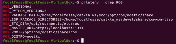
First let’s confirm what version of ROS we currently have active in our system.
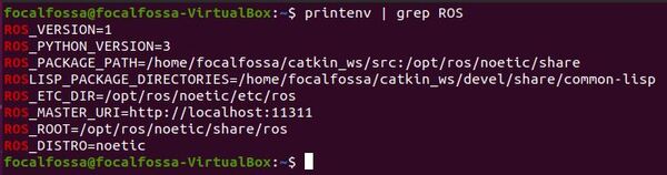
Open a new terminal window, and type the following command:
printenv | grep ROS
You can see that ROS 1 Noetic is the active ROS version right now.
Let’s switch to ROS 2 Foxy Fitzroy.
Open your bash file.
gedit ~/.bashrc
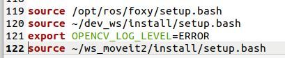
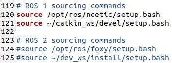
Scroll down to the bottom of your bash file, and you will see these lines.
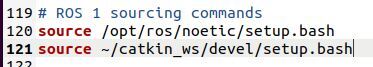
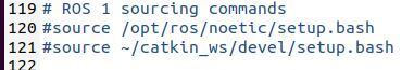
Comment the lines out so they look like this.
Now, make sure you have the following lines so that we make ROS 2 Foxy the active ROS version. These lines can go below the ROS 1 sourcing commands.
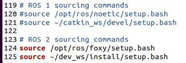
The two key lines that need to be uncommented are:
source /opt/ros/foxy/setup.bash
source ~/dev_ws/install/setup.bash
The name of the workspace for my ROS 2 work is dev_ws, but your workspace might be another name.
Save the file, and close it to go back to the terminal.
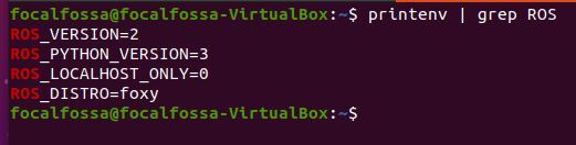
Open a new terminal window. Let’s see what the active ROS version is.
printenv | grep ROS
Switch From ROS 2 Foxy Fitzroy to ROS 1 Noetic
Now, let’s switch back from ROS 2 to ROS 1.
Uncomment the ROS 1 lines and comment out the ROS 2 lines.
gedit ~/.bashrc
Open a new terminal window, and check what version of ROS is currently active in your system.
That’s it! Keep building!