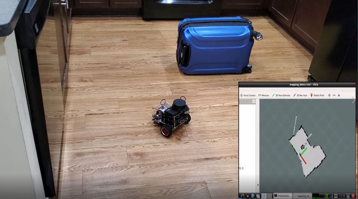
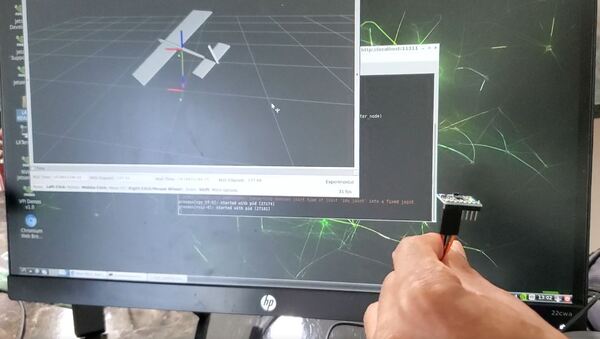
In this tutorial, we will learn how to use an NVIDIA Jetson Nano to read data from an MPU6050 IMU (Inertial measurement unit) sensor. We will also learn how to connect the MPU6050’s data to ROS, the most popular framework in the world for writing robot software. Here is what the final output will look like:
Real-World Applications
IMUs like the MPU6050 enable us to measure the acceleration and orientation of a robotic system. IMUs are common in both wheeled robots and aerial robots.
Prerequisites
- You have already set up your NVIDIA Jetson Nano (4GB, B01) with ROS.
You Will Need
In addition to the parts listed in the article I linked to in the Prerequisites, you will need the following components (#ad).
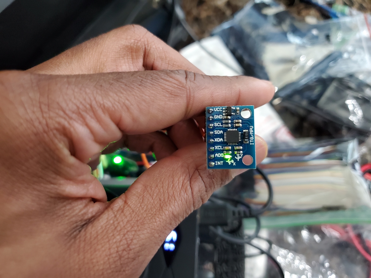
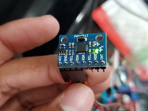
- MPU6050 (to make sure the electrical pins are stuck to the board, you can solder them like I did in this video here with the BNO055 board)
- Assorted breadboard jumper wires
- 400-point solderless breadboard (Optional)
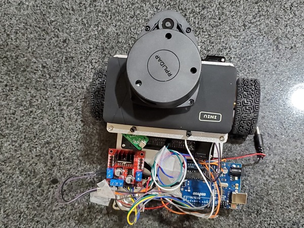
Once you finish this project, you can mount the IMU on anything that moves (drone, robot car, etc.) so you can measure the system’s acceleration and orientation.
Disclosure (#ad): As an Amazon Associate I earn from qualifying purchases.
Set Up the Hardware
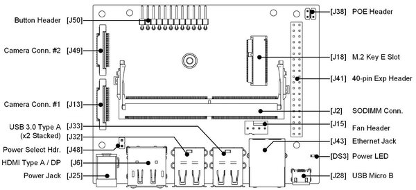
Here is the pinout diagram for the NVIDIA Jetson Nano B01.
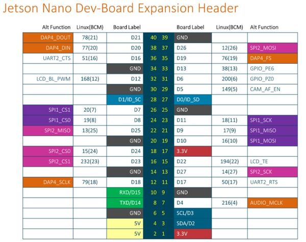
Make the following connections:
- Connect VCC of the MPU6050 to pin 17 (3.3V) of the Jetson Nano.
- Connect GND of the MPU6050 to pin 25 (GND) of the Jetson Nano.
- Connect SCL of the MPU6050 to pin 5 (SCL) of the Jetson Nano.
- Connect SDA of the MPU6050 to pin 3 (SDA) of the Jetson Nano.
Set Up the Communication Protocol
Our MPU6050 will use the I2C serial communication protocol. What this means is that data will be transferred from the IMU to the Jetson Nano one bit at a time.
Turn on your Jetson Nano.
Open a terminal window.
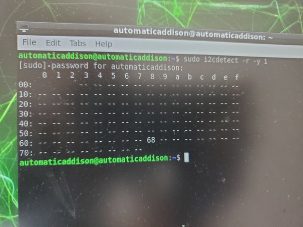
Type the following command to verify that you can see the MPU6050.
sudo i2cdetect -r -y 1
You can see that the address of the MPU6050 is 68.
Now let’s go through the different ways we can connect the MPU6050 to the Jetson Nano. We’ll go through one option at a time.
Write the Code
Option 1: Use the Adafruit Circuit Python Library
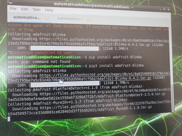
Install the adafruit-blinka library.
sudo apt-get update
pip3 install adafruit-blinka
It will take some time to download everything, so be patient. It might even look like it is frozen during the downloading process, but don’t worry, it is downloading.
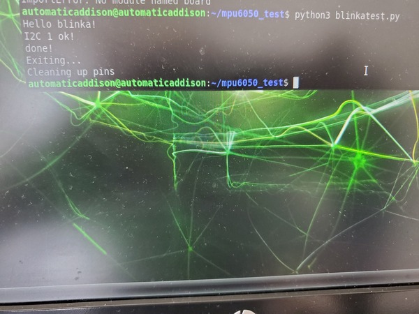
Test that everything is installed correctly.
Make a new directory named mpu6050_test.
mkdir mpu6050_test
Move to that directory.
cd mpu6050_test
Create a Python program called blinkatest.py.
gedit blinkatest.py
Write the following code.
import board
import busio

print("Hello blinka!")

# Try to create an I2C device
i2c = busio.I2C(board.SCL, board.SDA)
print("I2C 1 ok!")

print("done!")
Press save, and close it.
Run the code:
python3 blinkatest.py
Now let’s work with the Adafruit MPU6050 library.
Install the MPU6050 library.
pip3 install adafruit-circuitpython-mpu6050
Create a new program called mpu6050_simpletest.py.
gedit mpu6050_simpletest.py
Write the following code inside it. Credit to Adafruit for this code.
Save the file and close it.
Run the code.
python3 mpu6050_simpletest.py
Press CTRL+C when you’re done running the program.
Option 2: Using smbus
Here is another approach to reading data from the MPU6050. Credit to ElectronicWings for this method.
Install the smbus library.
sudo apt-get install python3-smbus
Create a program called mpu6050_simpletest2.py.
gedit mpu6050_simpletest2.py
Write the following code inside it.
'''
Read Gyro and Accelerometer by Interfacing Raspberry Pi with MPU6050 using Python
http://www.electronicwings.com
'''
import smbus #import SMBus module of I2C
from time import sleep #import
#some MPU6050 Registers and their Address
PWR_MGMT_1 = 0x6B
SMPLRT_DIV = 0x19
CONFIG = 0x1A
GYRO_CONFIG = 0x1B
INT_ENABLE = 0x38
ACCEL_XOUT_H = 0x3B
ACCEL_YOUT_H = 0x3D
ACCEL_ZOUT_H = 0x3F
GYRO_XOUT_H = 0x43
GYRO_YOUT_H = 0x45
GYRO_ZOUT_H = 0x47
def MPU_Init():
#write to sample rate register
bus.write_byte_data(Device_Address, SMPLRT_DIV, 7)
#Write to power management register
bus.write_byte_data(Device_Address, PWR_MGMT_1, 1)
#Write to Configuration register
bus.write_byte_data(Device_Address, CONFIG, 0)
#Write to Gyro configuration register
bus.write_byte_data(Device_Address, GYRO_CONFIG, 24)
#Write to interrupt enable register
bus.write_byte_data(Device_Address, INT_ENABLE, 1)
def read_raw_data(addr):
#Accelero and Gyro value are 16-bit
high = bus.read_byte_data(Device_Address, addr)
low = bus.read_byte_data(Device_Address, addr+1)
#concatenate higher and lower value
value = ((high << 8) | low)
#to get signed value from mpu6050
if(value > 32768):
value = value - 65536
return value
bus = smbus.SMBus(1) # or bus = smbus.SMBus(0) for older version boards
Device_Address = 0x68 # MPU6050 device address
MPU_Init()
print (" Reading Data of Gyroscope and Accelerometer")
while True:
#Read Accelerometer raw value
acc_x = read_raw_data(ACCEL_XOUT_H)
acc_y = read_raw_data(ACCEL_YOUT_H)
acc_z = read_raw_data(ACCEL_ZOUT_H)
#Read Gyroscope raw value
gyro_x = read_raw_data(GYRO_XOUT_H)
gyro_y = read_raw_data(GYRO_YOUT_H)
gyro_z = read_raw_data(GYRO_ZOUT_H)
#Full scale range +/- 250 degree/C as per sensitivity scale factor
Ax = acc_x/16384.0
Ay = acc_y/16384.0
Az = acc_z/16384.0
Gx = gyro_x/131.0
Gy = gyro_y/131.0
Gz = gyro_z/131.0
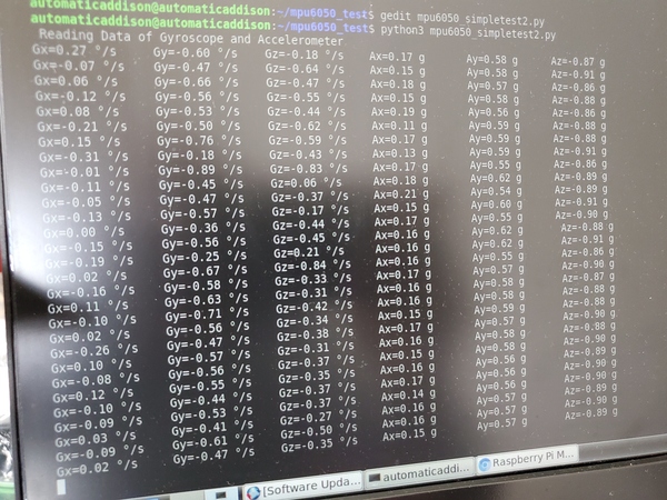
print ("Gx=%.2f" %Gx, u'\u00b0'+ "/s", "\tGy=%.2f" %Gy, u'\u00b0'+ "/s", "\tGz=%.2f" %Gz, u'\u00b0'+ "/s", "\tAx=%.2f g" %Ax, "\tAy=%.2f g" %Ay, "\tAz=%.2f g" %Az)
sleep(1)
Save the file and close it.
Run the code.
python3 mpu6050_simpletest2.py
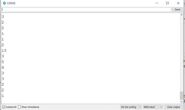
Here is the output:
Option 3: Using smbus again
Here is our third and final approach to reading data from the MPU6050.
Create a program called mpu6050_simpletest3.py.
gedit mpu6050_simpletest3.py
Write the following code inside it.
"""This program handles the communication over I2C
between a Jetson Nano and a MPU-6050 Gyroscope / Accelerometer combo.
Made by: Dennis/TW
Released under the MIT License
Copyright 2019
"""
import smbus
from time import sleep
class mpu6050:
# Global Variables
GRAVITIY_MS2 = 9.80665
address = None
bus = smbus.SMBus(1)
# Scale Modifiers
ACCEL_SCALE_MODIFIER_2G = 16384.0
ACCEL_SCALE_MODIFIER_4G = 8192.0
ACCEL_SCALE_MODIFIER_8G = 4096.0
ACCEL_SCALE_MODIFIER_16G = 2048.0
GYRO_SCALE_MODIFIER_250DEG = 131.0
GYRO_SCALE_MODIFIER_500DEG = 65.5
GYRO_SCALE_MODIFIER_1000DEG = 32.8
GYRO_SCALE_MODIFIER_2000DEG = 16.4
# Pre-defined ranges
ACCEL_RANGE_2G = 0x00
ACCEL_RANGE_4G = 0x08
ACCEL_RANGE_8G = 0x10
ACCEL_RANGE_16G = 0x18
GYRO_RANGE_250DEG = 0x00
GYRO_RANGE_500DEG = 0x08
GYRO_RANGE_1000DEG = 0x10
GYRO_RANGE_2000DEG = 0x18
# MPU-6050 Registers
PWR_MGMT_1 = 0x6B
PWR_MGMT_2 = 0x6C
SELF_TEST_X = 0x0D
SELF_TEST_Y = 0x0E
SELF_TEST_Z = 0x0F
SELF_TEST_A = 0x10
ACCEL_XOUT0 = 0x3B
ACCEL_XOUT1 = 0x3C
ACCEL_YOUT0 = 0x3D
ACCEL_YOUT1 = 0x3E
ACCEL_ZOUT0 = 0x3F
ACCEL_ZOUT1 = 0x40
TEMP_OUT0 = 0x41
TEMP_OUT1 = 0x42
GYRO_XOUT0 = 0x43
GYRO_XOUT1 = 0x44
GYRO_YOUT0 = 0x45
GYRO_YOUT1 = 0x46
GYRO_ZOUT0 = 0x47
GYRO_ZOUT1 = 0x48
ACCEL_CONFIG = 0x1C
GYRO_CONFIG = 0x1B
def __init__(self, address):
self.address = address
# Wake up the MPU-6050 since it starts in sleep mode
self.bus.write_byte_data(self.address, self.PWR_MGMT_1, 0x00)
# I2C communication methods
def read_i2c_word(self, register):
"""Read two i2c registers and combine them.
register -- the first register to read from.
Returns the combined read results.
"""
# Read the data from the registers
high = self.bus.read_byte_data(self.address, register)
low = self.bus.read_byte_data(self.address, register + 1)
value = (high << 8) + low
if (value >= 0x8000):
return -((65535 - value) + 1)
else:
return value
# MPU-6050 Methods
def get_temp(self):
"""Reads the temperature from the onboard temperature sensor of the MPU-6050.
Returns the temperature in degrees Celcius.
"""
# Get the raw data
raw_temp = self.read_i2c_word(self.TEMP_OUT0)
# Get the actual temperature using the formule given in the
# MPU-6050 Register Map and Descriptions revision 4.2, page 30
actual_temp = (raw_temp / 340) + 36.53
# Return the temperature
return actual_temp
def set_accel_range(self, accel_range):
"""Sets the range of the accelerometer to range.
accel_range -- the range to set the accelerometer to. Using a
pre-defined range is advised.
"""
# First change it to 0x00 to make sure we write the correct value later
self.bus.write_byte_data(self.address, self.ACCEL_CONFIG, 0x00)
# Write the new range to the ACCEL_CONFIG register
self.bus.write_byte_data(self.address, self.ACCEL_CONFIG, accel_range)
def read_accel_range(self, raw = False):
"""Reads the range the accelerometer is set to.
If raw is True, it will return the raw value from the ACCEL_CONFIG
register
If raw is False, it will return an integer: -1, 2, 4, 8 or 16. When it
returns -1 something went wrong.
"""
# Get the raw value
raw_data = self.bus.read_byte_data(self.address, self.ACCEL_CONFIG)
if raw is True:
return raw_data
elif raw is False:
if raw_data == self.ACCEL_RANGE_2G:
return 2
elif raw_data == self.ACCEL_RANGE_4G:
return 4
elif raw_data == self.ACCEL_RANGE_8G:
return 8
elif raw_data == self.ACCEL_RANGE_16G:
return 16
else:
return -1
def get_accel_data(self, g = False):
"""Gets and returns the X, Y and Z values from the accelerometer.
If g is True, it will return the data in g
If g is False, it will return the data in m/s^2
Returns a dictionary with the measurement results.
"""
# Read the data from the MPU-6050
x = self.read_i2c_word(self.ACCEL_XOUT0)
y = self.read_i2c_word(self.ACCEL_YOUT0)
z = self.read_i2c_word(self.ACCEL_ZOUT0)
accel_scale_modifier = None
accel_range = self.read_accel_range(True)
if accel_range == self.ACCEL_RANGE_2G:
accel_scale_modifier = self.ACCEL_SCALE_MODIFIER_2G
elif accel_range == self.ACCEL_RANGE_4G:
accel_scale_modifier = self.ACCEL_SCALE_MODIFIER_4G
elif accel_range == self.ACCEL_RANGE_8G:
accel_scale_modifier = self.ACCEL_SCALE_MODIFIER_8G
elif accel_range == self.ACCEL_RANGE_16G:
accel_scale_modifier = self.ACCEL_SCALE_MODIFIER_16G
else:
print("Unkown range - accel_scale_modifier set to self.ACCEL_SCALE_MODIFIER_2G")
accel_scale_modifier = self.ACCEL_SCALE_MODIFIER_2G
x = x / accel_scale_modifier
y = y / accel_scale_modifier
z = z / accel_scale_modifier
if g is True:
return {'x': x, 'y': y, 'z': z}
elif g is False:
x = x * self.GRAVITIY_MS2
y = y * self.GRAVITIY_MS2
z = z * self.GRAVITIY_MS2
return {'x': x, 'y': y, 'z': z}
def set_gyro_range(self, gyro_range):
"""Sets the range of the gyroscope to range.
gyro_range -- the range to set the gyroscope to. Using a pre-defined
range is advised.
"""
# First change it to 0x00 to make sure we write the correct value later
self.bus.write_byte_data(self.address, self.GYRO_CONFIG, 0x00)
# Write the new range to the ACCEL_CONFIG register
self.bus.write_byte_data(self.address, self.GYRO_CONFIG, gyro_range)
def read_gyro_range(self, raw = False):
"""Reads the range the gyroscope is set to.
If raw is True, it will return the raw value from the GYRO_CONFIG
register.
If raw is False, it will return 250, 500, 1000, 2000 or -1. If the
returned value is equal to -1 something went wrong.
"""
# Get the raw value
raw_data = self.bus.read_byte_data(self.address, self.GYRO_CONFIG)
if raw is True:
return raw_data
elif raw is False:
if raw_data == self.GYRO_RANGE_250DEG:
return 250
elif raw_data == self.GYRO_RANGE_500DEG:
return 500
elif raw_data == self.GYRO_RANGE_1000DEG:
return 1000
elif raw_data == self.GYRO_RANGE_2000DEG:
return 2000
else:
return -1
def get_gyro_data(self):
"""Gets and returns the X, Y and Z values from the gyroscope.
Returns the read values in a dictionary.
"""
# Read the raw data from the MPU-6050
x = self.read_i2c_word(self.GYRO_XOUT0)
y = self.read_i2c_word(self.GYRO_YOUT0)
z = self.read_i2c_word(self.GYRO_ZOUT0)
gyro_scale_modifier = None
gyro_range = self.read_gyro_range(True)
if gyro_range == self.GYRO_RANGE_250DEG:
gyro_scale_modifier = self.GYRO_SCALE_MODIFIER_250DEG
elif gyro_range == self.GYRO_RANGE_500DEG:
gyro_scale_modifier = self.GYRO_SCALE_MODIFIER_500DEG
elif gyro_range == self.GYRO_RANGE_1000DEG:
gyro_scale_modifier = self.GYRO_SCALE_MODIFIER_1000DEG
elif gyro_range == self.GYRO_RANGE_2000DEG:
gyro_scale_modifier = self.GYRO_SCALE_MODIFIER_2000DEG
else:
print("Unkown range - gyro_scale_modifier set to self.GYRO_SCALE_MODIFIER_250DEG")
gyro_scale_modifier = self.GYRO_SCALE_MODIFIER_250DEG
x = x / gyro_scale_modifier
y = y / gyro_scale_modifier
z = z / gyro_scale_modifier
return {'x': x, 'y': y, 'z': z}
def get_all_data(self):
"""Reads and returns all the available data."""
temp = get_temp()
accel = get_accel_data()
gyro = get_gyro_data()
return [accel, gyro, temp]
if __name__ == "__main__":
while(1):
mpu = mpu6050(0x68)
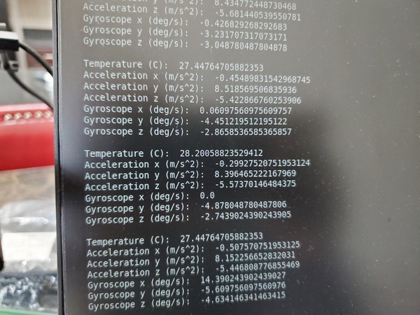
print("Temperature (C): ", mpu.get_temp())
accel_data = mpu.get_accel_data()
print("Acceleration x (m/s^2): ", accel_data['x'])
print("Acceleration y (m/s^2): ", accel_data['y'])
print("Acceleration z (m/s^2): ", accel_data['z'])
gyro_data = mpu.get_gyro_data()
print("Gyroscope x (deg/s): ", gyro_data['x'])
print("Gyroscope y (deg/s): ", gyro_data['y'])
print("Gyroscope z (deg/s): ", gyro_data['z'])
sleep(1)
Save the file and close it.
Run the code.
python mpu6050_simpletest3.py
Here is the output:
Connect the MPU6050 IMU to ROS
Now let’s connect the MPU6050 to ROS. We want to publish the data we read from the MPU6050 to a ROS topic. Let’s take a look at two different ways to do this using pre-built ROS packages.
Option 1
Install and Build the Package
Go to your catkin workspace.
cd ~/catkin_ws/src
Clone the package. This package was created by roboticists at Oregon State University.
git clone https://github.com/OSUrobotics/mpu_6050_driver.git
cd mpu_6050_driver/scripts
gedit tf_broadcaster_imu.py
Write this code.
Save the file, and close it.
Open the imu_node.py file.
gedit imu_node.py
Go down to lines 93 and 94, and add a queue_size of 10. Here is how the code should look:
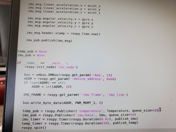
Save the file and close it.
Change permissions of both files.
chmod +x imu_node.py
chmod +x tf_broadcaster_imu.py
Move to the root.
cd ~/catkin_ws/
Build the package.
catkin_make
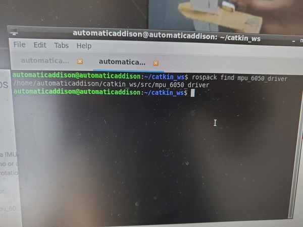
Open a new terminal window, and print the path to your new ROS package named mpu_6050_driver.
rospack find mpu_6050_driver
To see if our package depends on other packages, type these commands. Ignore any error messages you see in the terminal:
rosdep update
rosdep check mpu_6050_driver
You should see a message that says “All system dependencies have been satisfied.”
Run the Node
Now we want to run the node that is inside the mpu_6050_driver package.
Open a new terminal window, and launch ROS.
cd ~/catkin_ws/
roscore
Open another terminal window, and run the IMU node.
rosrun mpu_6050_driver imu_node.py
Open another terminal window, and type the following command:
rosrun mpu_6050_driver tf_broadcaster_imu.py
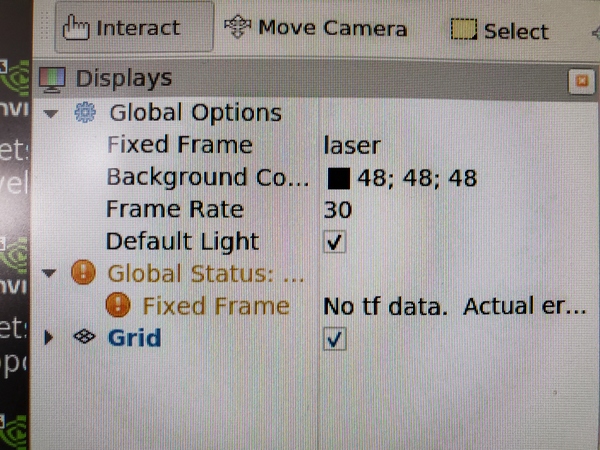
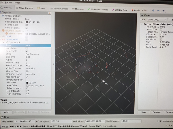
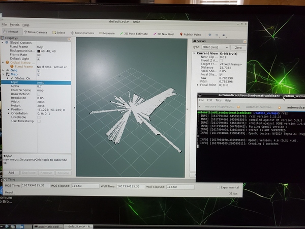
Open Rviz.
rosrun rviz rviz
Change the Fixed Frame parameter under Global Options to imu_link.
Click the Add button in the bottom-left of the Displays menu.
Add TF.
Also add Imu if you have that option. Under the Imu dropdown in the Displays, change the Topic to /imu/data.
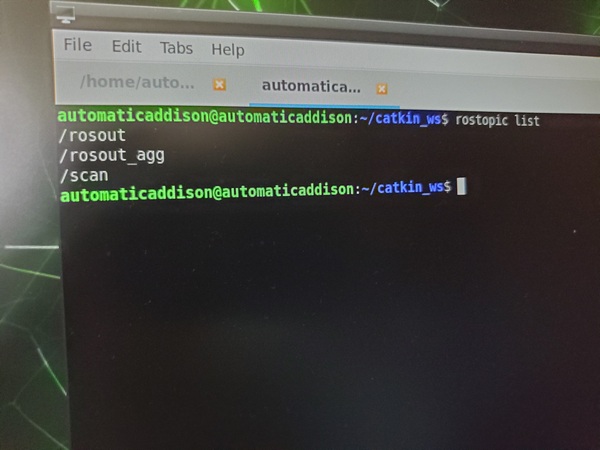
Let’s see the active ROS topics. Open up a new terminal and type:
rostopic list
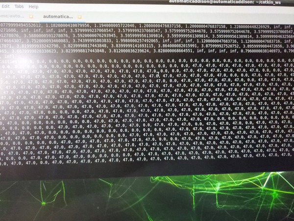
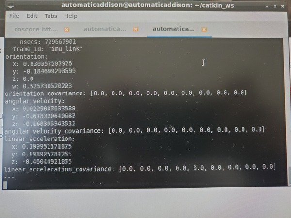
Open another terminal window, and visualize the imu data.
rostopic echo /imu/data
Press CTRL+C on all windows when you’re done.
Option 2
Install and Build the Package
For this option, we will use the IMU Complementary Filter package. Type the following commands to install this package.
cd ~/catkin_ws/src
sudo apt-get install ros-melodic-imu-tools
Install the MPU 6050 driver package created by Robotics and ROS Learning. He gives a great walkthrough about this package in this video on YouTube. Type this single command below.
git clone https://github.com/bandasaikrishna/orientations_from_IMU_MPU_6050.git
Using the file explorer on your Jetson Nano, copy all of the contents of that folder you just imported from GitHub and paste them into your mpu_6050_driver package from the previous section. When asked if you want to overwrite, yes you want to overwrite all duplicated folders.
Go to the scripts folder.
cd ~/catkin_ws/src/mpu_6050_driver/scripts
Change permissions on the imu_node.py file and tf_broadcaster_imu.py nodes.
chmod +x imu_node.py
chmod +x tf_broadcaster_imu.py
Build the package.
cd ~/catkin_ws/
catkin_make
Check dependencies. Open a new terminal window, and type:
rosdep check mpu_6050_driver
You should see a message that says “All system dependencies have been satisfied.”
Launch It
Now we want to launch the package.
Open a new terminal window, and type the following command:
roslaunch mpu_6050_driver imu_demo.launch
Let’s see the active ROS topics. Open up a new terminal and type:
rostopic list
That’s it! If for some reason, that GitHub code is no longer available, you can download the code here from my files.
Keep building!