In this post, we will take a look out how to draw the force vector diagrams for an omni-directional mobile robot with Mecanum wheels. But before we do that, let’s take a look at a few real-world applications of these vehicles.
Real-World Applications
The following are some common real-world applications for Mecanum-wheeled robots:
- Industrial forklifts: Moving long loads sideways through narrow aisles and doors.
- Military: Rescue missions and hazardous environment exploration in tight spaces.
- Medical: Powered wheelchairs that can maneuver in congested areas.
- Aviation: Transport of helicopters or large pieces of aircraft
Below is a video of Mecanum-wheeled robots helping to move a piece of a passenger train.
Here is a Mecanum-wheeled robot transporting a helicopter.
Here is a sports car design that uses Mecanum wheels. Makes parallel parking a breeze!
Force Vector Diagrams
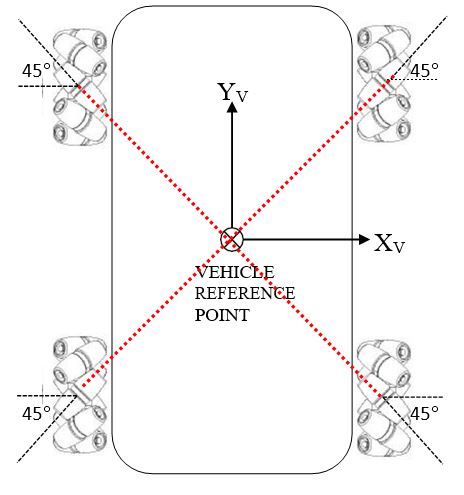
The robot schematic diagram below consists of four Mecanum wheels. Each wheel is driven by a motor and contains a set of passive rubber cylinders that are oriented at an angle of 45° to the axis of rotation of the wheel (the axis of rotation of the wheel is the imaginary line that goes through the center of the wheel).
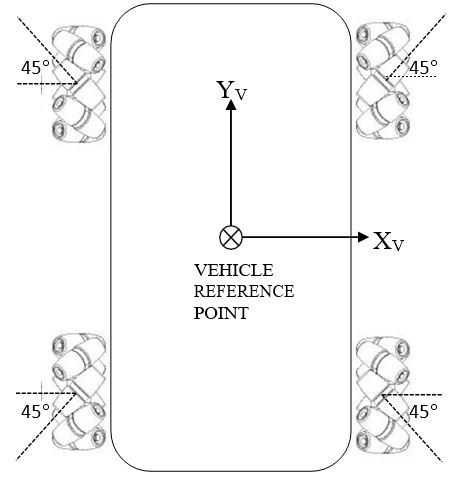
The 45° orientation of the rollers is what gives the robot the ability to move in directions other than just forwards and backwards.
Another thing to note is that the rubber rollers of the robot are oriented as an ‘X’ (i.e. the red line below). This X configuration enables the Mecanum-wheeled robot to be able to move in any direction (I’ll show why this is the case in the force/rotation diagrams).
The rollers could also be oriented as an ‘O’ as seen from the top, but in this case, we will assume an X configuration.
Before I draw the force/rotation diagrams that cause the different directions of motion of the robot, let’s take a look at the concept of friction because it plays an important role in how the Mecanum wheels do what they do.
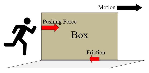
Below we have a person trying to push a box across a floor.
The person exerts a pushing force on the box. As the box moves to the right, the surface of the floor exerts a frictional force that acts in the opposite direction of the motion of the box. The person must make sure he pushes hard enough on the box to overcome that frictional force; otherwise, the box won’t move.
Similarly, in the case of the omni-directional Mecanum-wheeled robot, as the wheels rotate, each rubber roller on each wheel makes contact with the surface of the ground at an angle of 45° to the axis of rotation of the wheel.
At the moment each rubber roller makes contact with the ground, the surface of the ground exerts a frictional force that acts in the opposite direction of the force exerted on the ground surface by the rubber roller. There are four frictional forces that act on the robot simultaneously (one for each wheel). It is these forces that cause the robot to move.
In what direction does the robot move? The direction the robot moves is determined by the magnitude and direction of each of the four frictional forces.
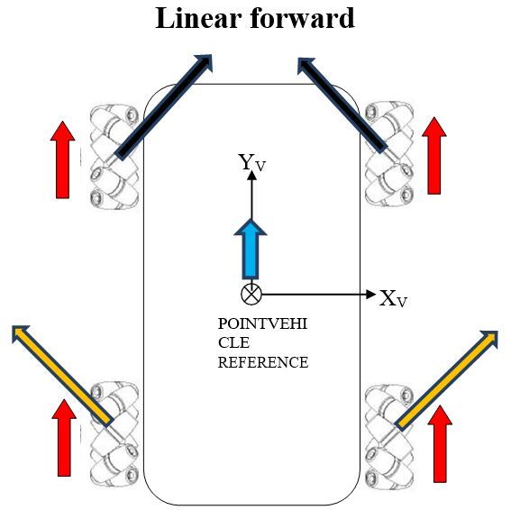
Below are the vehicle diagrams (as shown from above the robot) that show how all of this works. The diagrams show how each wheel must move, both direction and angular rate (long vector for high angular rate, short vector for small), so that the indicated motion results. The diagrams also show which way force is applied on the robot when the wheels rotate along the surface of the ground, with the key point being that the sum of the four force vectors (i.e. resultant force) equals the direction of motion of the reference point (which is located in the center of the robot).
- The red arrows show the magnitude and direction of the rotation of the wheels.
- The black and orange arrows show the frictional force vectors that act when the rubber roller makes contact with the ground surface. Although these vectors are shown above the robot, they act underneath the robot. They are the frictional forces that act on each rubber roller when it touches the ground surface.
- The blue arrow shows the motion of the vehicle reference point.
Now, we add up the force vectors on the front and rear of the robot to calculate the resultant force (i.e. motion of the robot/vehicle reference point).
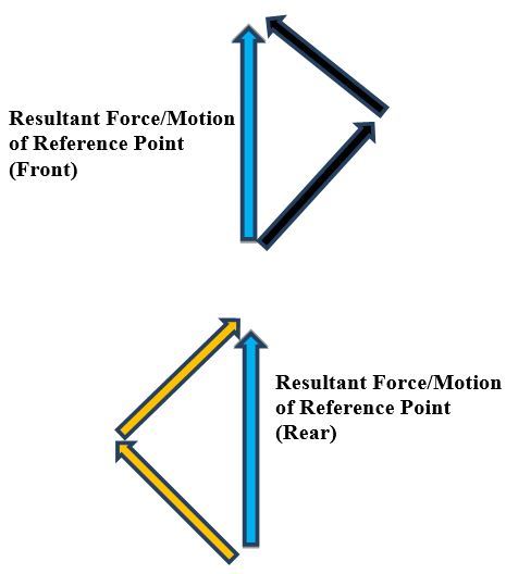
Using the head-to-tail method to add the force vectors (black and orange arrows above), we see that the x-components of these force vectors on both the front and rear of the vehicle cancel out, so all that is left are the y-components. It is this net, resultant force in the positive y-direction, which results in straight-ahead, forward motion of the robot (i.e. vehicle reference point).
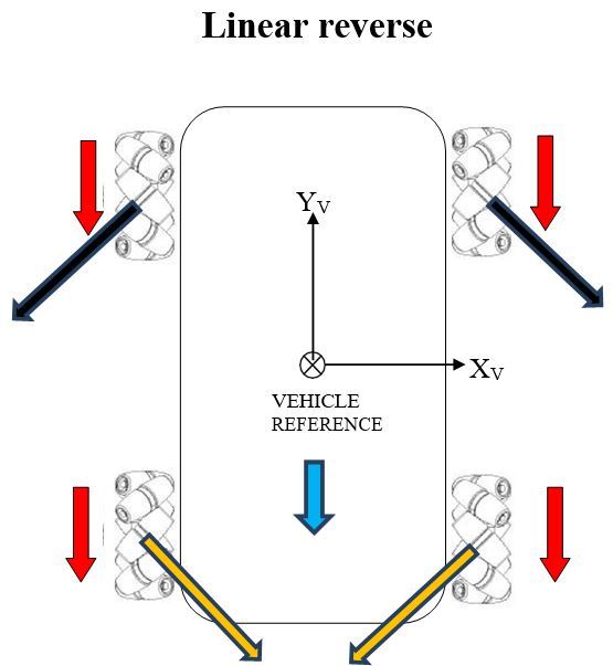
Now, we add up the force vectors on the front and rear of the robot to calculate the resultant force (i.e. motion of the robot/vehicle reference point).
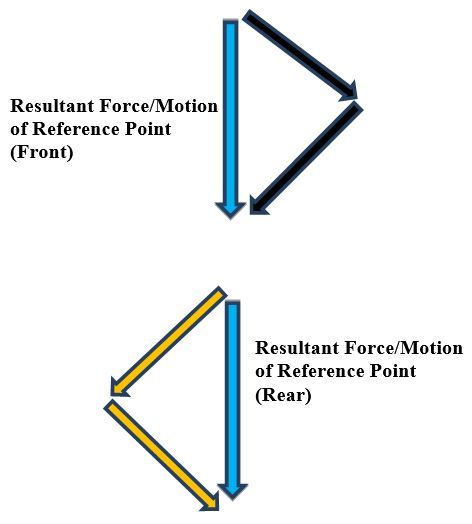
Similar to the linear forward case, the x-components of the force vectors on both the front and rear of the vehicle cancel out, so all that is left are the y-components. The net force is in the negative y-direction, causing the robot (i.e. vehicle reference point) to move in reverse.
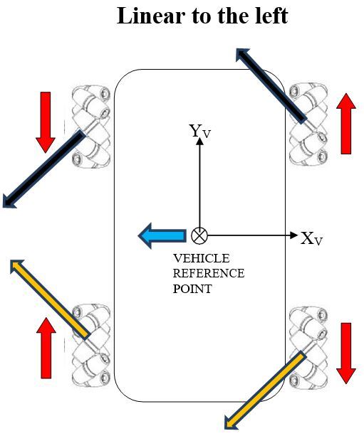
Now, we add up the force vectors on the front and rear of the robot to calculate the resultant force (i.e. motion of the robot/vehicle reference point).
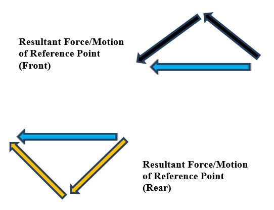
Using the head-to-tail method to add the force vectors (black and orange arrows above), we see that the y-components of these force vectors on both the front and rear of the vehicle cancel out, so all that is left are the x-components. It is this net, resultant force in the negative x-direction, which causes the robot to move linearly to the left.
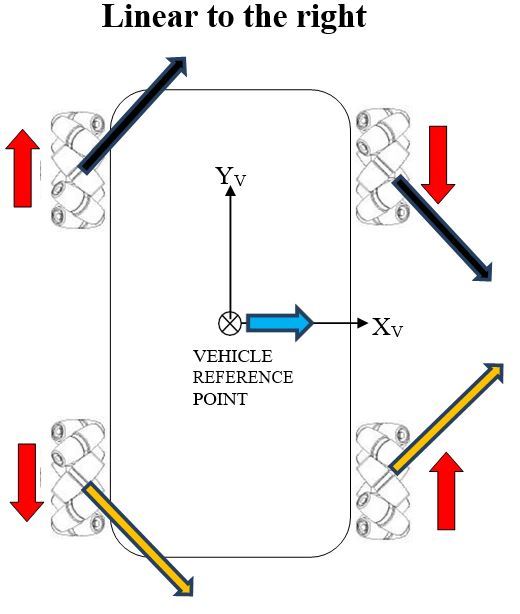
Now, we add up the force vectors on the front and rear of the robot to calculate the resultant force (i.e. motion of the robot/vehicle reference point).
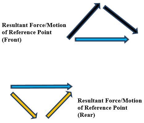
Using the head-to-tail method to add the force vectors (black and orange arrows above), we see that the y-components of these force vectors on both the front and rear of the vehicle cancel out, so all that is left are the x-components. It is this net, resultant force in the positive x-direction which causes the robot to move in a sideways direction to the right.
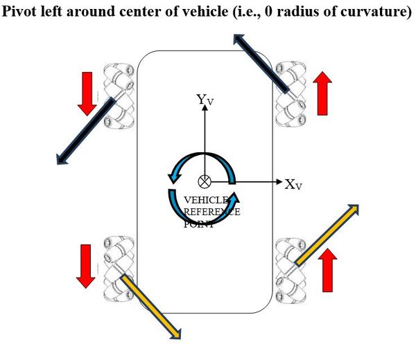
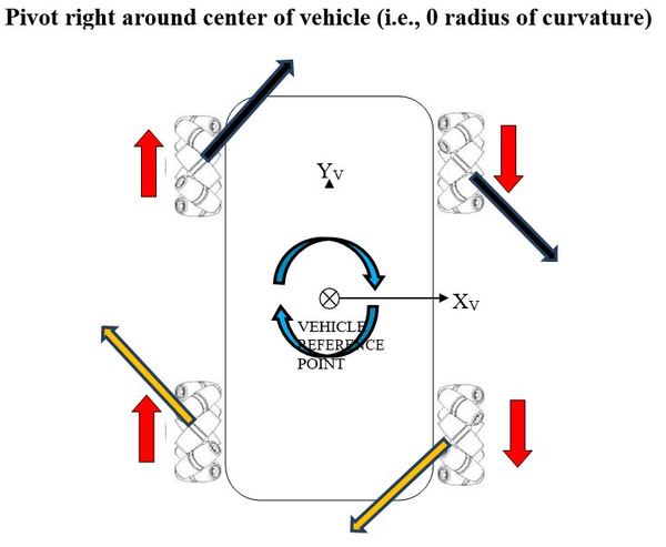
Finally, here are the force vector diagrams for when the robot spins in-place, either to the left or to the right.