In this post, I will show you how to make a remote-controlled robot using Raspberry Pi.
Special shout out to Matt Timmons-Brown for this project idea. He is the author of a really good book on Raspberry Pi robotics: (Learn Robotics with Raspberry Pi). Go check it out!
Video
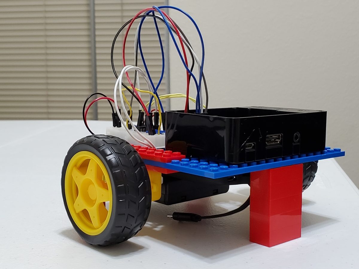
Here is a video of what we will build in this tutorial.
Requirements
Here are the requirements:
- Make a remote-controlled robot using Raspberry Pi and the Bluetooth-ready Nintendo Wii remote control.
You Will Need
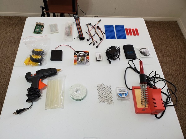
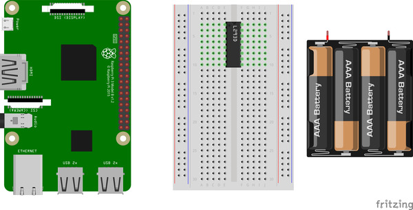
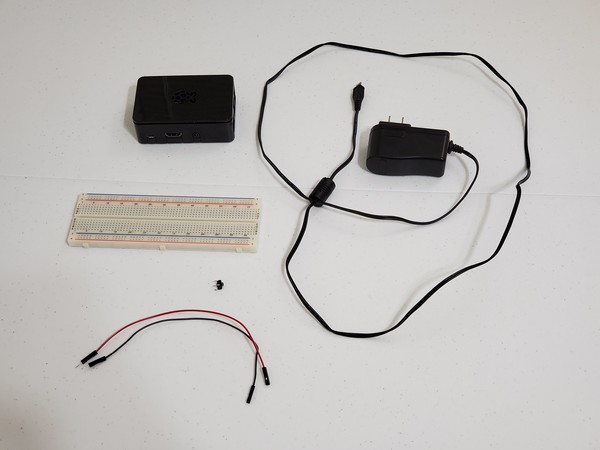
The following components are used in this project. You will need:
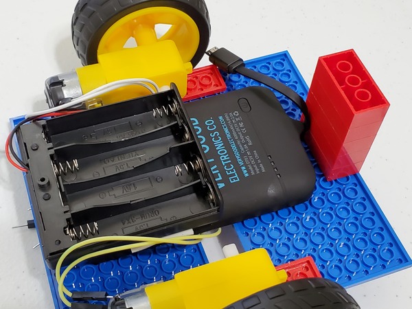
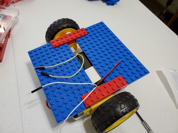
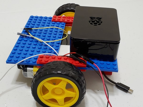
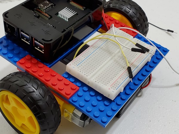
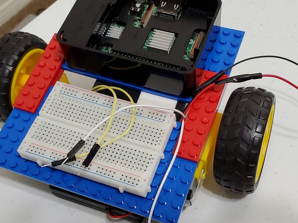
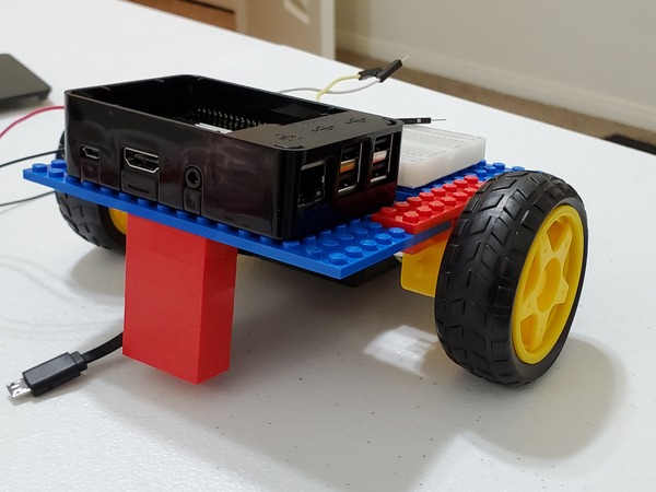
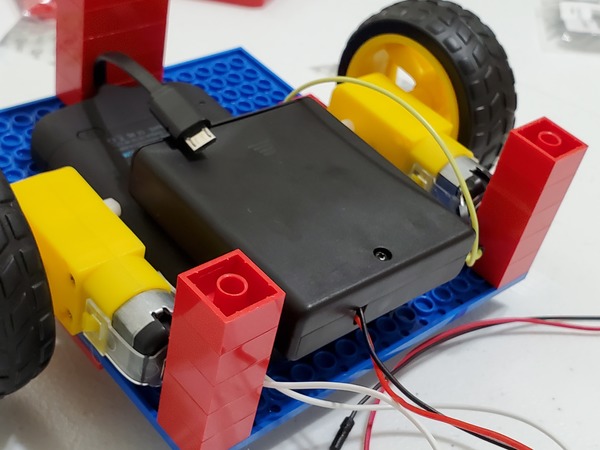
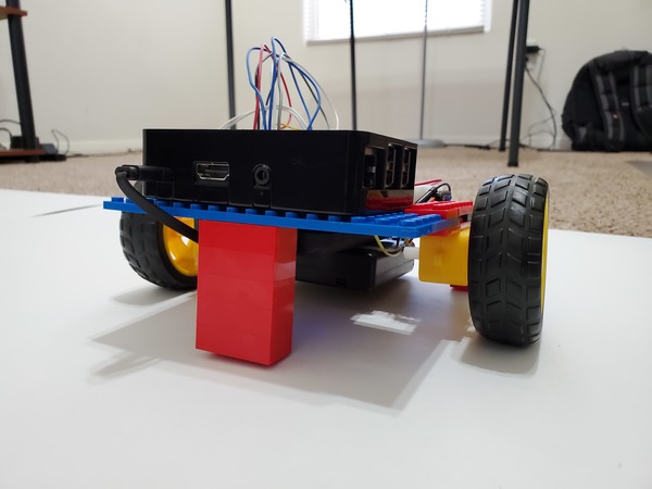
- Wheeled Robot Powered by Raspberry Pi
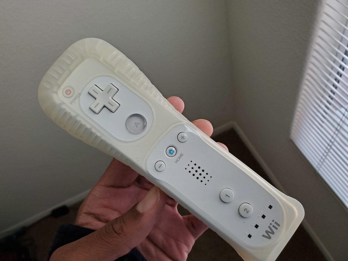
- Nintendo Wii Remote Control (available from eBay)
Directions
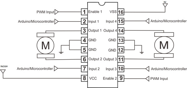
Familiarizing Yourself with the L293D H-Bridge Motor Driver
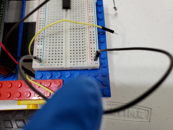
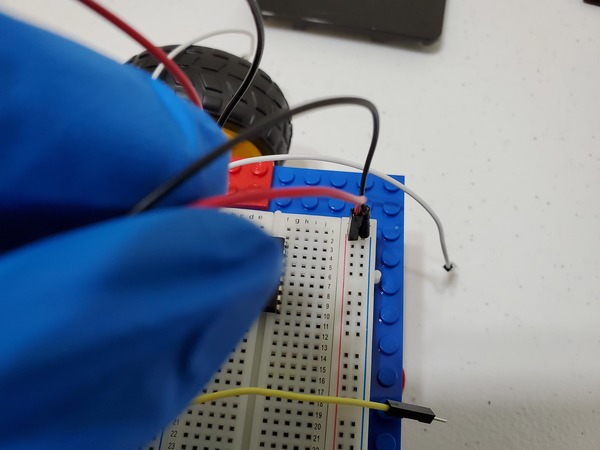
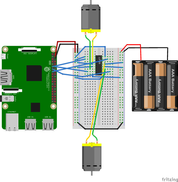
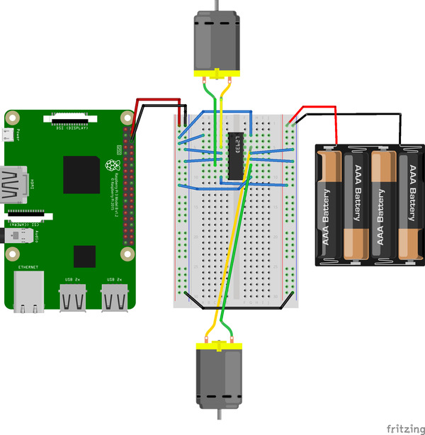
You may recall in my post where we constructed the robot’s body that we had four input pins on the L293D motor controller (two for each motor). These input pins control the direction of the motors. For example, for the motor attached to the side of the motor controller connected to Inputs 3 and 4 of the L293D, we have:
| Input 3 | Input 4 | Motor |
| HIGH | HIGH | OFF |
| HIGH | LOW | Rotation in one direction |
| LOW | HIGH | Rotation in the other direction |
| LOW | LOW | OFF |
HIGH = voltage applied; LOW = voltage not applied
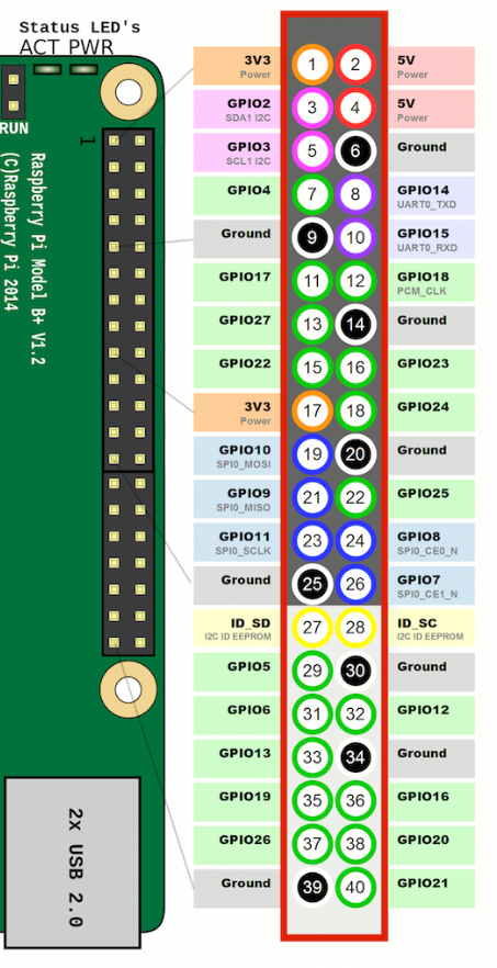
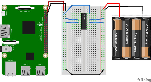
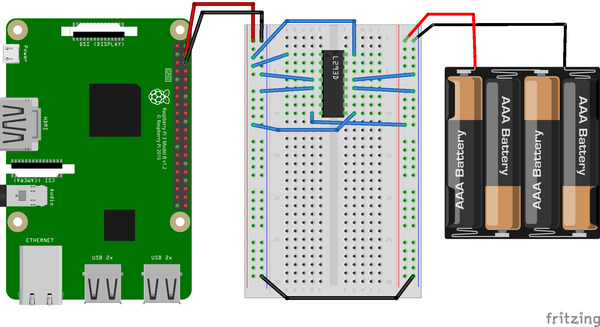
The four input pins set their signals from the Raspberry Pi’s GPIO (General Purpose Input/Output) pins.
To make all of this work, under the hood of the L293D motor controller, there is an H-bridge circuit. An H-bridge circuit enables a motor to be driven both forwards and backwards. It is a useful circuit in robotics.
Here is what an H bridge looks like:
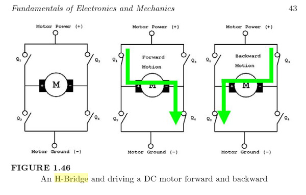
Image Source: Practical and Experimental Robotics
An H-bridge is made from electronically-controlled switches (rather than finger-controlled, such as the wall light switch in your bedroom) known as transistors.
Switch 1 and Switch 2 as well as Switch 3 and Switch 4 can never be closed at the same time. Otherwise, a bad short circuit would be created.
If Switch 3 and Switch 2 close at the same time, the motor spins in one direction. If Switch 1 and Switch 4 are closed (and Switch 2 and Switch 3 remain open), the motor will spin in the other direction because of the change in the path of the electric current.
Testing Your Robot to See If It Can Move
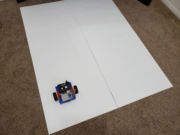
We need to verify that the robot can move properly. We will create a basic program in Python that will make the robot move in a box-shaped pattern three times.
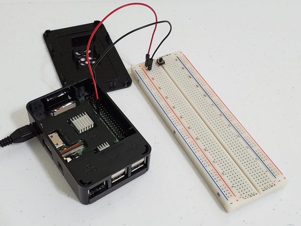
First, power up the Raspberry Pi by connecting it to a wall outlet. Best practice is to connect your Raspberry Pi to a wall outlet (rather than the battery pack) when you are programming it.
Connect to your Raspberry Pi either through Putty or VNC Viewer. I’ll do VNC Viewer.
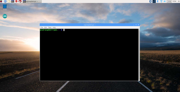
Open a terminal window. Move to the directory where you are saving your robotics projects.
In my case, I type:
cd robot
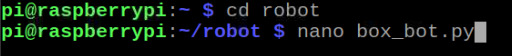
I then create a program in Python by typing:
nano box_bot.py
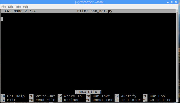
I called the program box_bot.py because the robot will move in a shape that looks like a box.
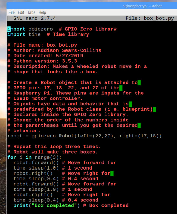
Here is the Python code for the program:
import gpiozero # GPIO Zero library
import time # Time library
# File name: box_bot.py
# Author: Addison Sears-Collins
# Date created: 5/27/2019
# Python version: 3.5.3
# Description: Makes a wheeled robot move in a
# shape that looks like a box.
# Create a Robot object that is attached to
# GPIO pins 17, 18, 22, and 27 of the
# Raspberry Pi. These pins are inputs for the
# L293D motor controller.
# Objects have data and behavior that is
# predefined by the Robot class (i.e. blueprint)
# declared inside the GPIO Zero library.
# Change the order of the numbers inside
# the parentheses until you get the desired
# behavior.
robot = gpiozero.Robot(left=(22,27), right=(17,18))
# Repeat this loop three times.
# Robot will make three boxes.
for i in range(3):
robot.forward() # Move forward for
time.sleep(1.0) # 1 second
robot.right() # Move right for
time.sleep(0.4) # 0.4 second
robot.forward() # Move forward for
time.sleep(1.0) # 1 second
robot.right() # Move right for
time.sleep(0.4) # 0.4 second
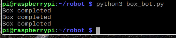
print("Box completed") # Box completed
Exit the program editor by pressing CTRL-X. Make sure to save it, so press Y, then press ENTER to write (i.e. save) the file to the directory.
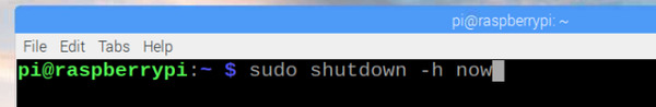
Shutdown your Raspberry Pi by typing:
sudo shutdown -h now
Wait 5 seconds (or when you see the tiny green light on the Raspberry Pi is no longer illuminated), and unplug your Raspberry Pi from the wall.
Now, turn on the 4xAA battery holder.
Connect the Raspberry Pi battery pack to the Raspberry Pi.
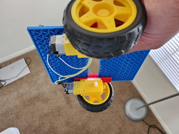
Place the robot on a smooth floor in a wide open flat space, away from any object. You could also hold the body in your hand. Grip it by the back of the robot, being careful to keep your hands away from the wheels.
Run the box_bot.py program by opening a terminal window, going to your robot directory (or whatever directory your program is saved in) and typing:
python3 box_bot.py
Your robot likely won’t make perfect boxes and might not even make fewer than three boxes (due to the weight the motors are pulling). That is fine. The key to this exercise is to just make sure the robot can go forwards and make a right turn.
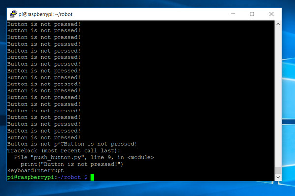
If you need to stop the robot at any time, you can press CTRL-C.
If you see that your robot is not moving like it should, switch the order of the numbers inside the parentheses on this line:
robot = gpiozero.Robot(left=(22,27), right(17,18))
You can also edit the sleep time in your program. Also check to make sure the wiring is exactly like I indicated in my wheeled robot post.
If your robot isn’t moving at all, don’t worry, robots rarely work as they should the first time around. Keep tinkering with the code until you get the desired result. Take your time. No need to hurry.
Setting up the Nintendo Wii Remote Control
Power up your Raspberry Pi.
Open a terminal window. Type in the following command, and wait while it updates:
sudo apt-get update
The Raspberry Pi has a list of all the software to packages that are available for installation. If you don’t run sudo apt-get update before installing a new software package, you might end up with an outdated piece of software.
Install the Bluetooth package.
Bluetooth is a wireless technology that enables data to be sent back and forth over short distances using radio waves.
sudo apt-get install bluetooth
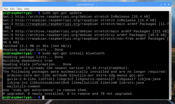
Bluetooth might already be installed on your Raspberry Pi. If it is, you will get a message saying so.
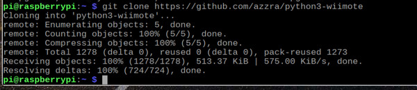
Download the open source cwiid Python library that enables the Raspberry Pi to receive information from the remote control.
Type this in the terminal window:
git clone https://github.com/azzra/python3-wiimote
Install four additional software packages:
sudo apt-get install bison flex automake libbluetooth-dev
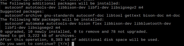
Type Y and press ENTER to continue. Wait while the software installs on your Raspberry Pi.
Move to the python3-wiimote directory.
cd python3-wiimote
Compile the python3-wiimote source code by typing in these commands, one by one in order:
aclocal
autoconf
./configure
make
sudo make install
The cwiid library is now installed on your Raspberry Pi.
Move to the robot directory:
cd
cd robot
Create a new Python program.
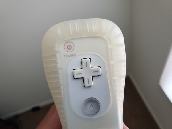
This program enables the Nintendo Wii remote control to make the robot move forwards (UP button), backwards (DOWN button), to the right (RIGHT button), to the left (LEFT button), and stop (B button).
nano wii_remote.py
Here is the Python code:
import gpiozero  # GPIO Zero library
import cwiid  # Wii library

# File name: wii_remote.py
# Date created: 5/27/2019
# Python version: 3.5.3
# Code source (Matt-Timmons Brown): https://github.com/the-raspberry-pi-guy/raspirobots
# Description: This program enables the
# Nintendo Wii remote control to make a robot
# move forwards (UP), backwards (DOWN), to the
# right (RIGHT), to the left (LEFT), and stop
# (B).

# Create a Robot object that is attached to
# GPIO pins 17, 18, 22, and 27 of the
# Raspberry Pi. These pins are inputs for the
# L293D motor controller.
robot = gpiozero.Robot(left=(22,27), right=(17,18))

print("Press down and hold buttons 1 and 2 on",
      " the Nintendo Wii remote.")
print(" ")
print("Hold down until you see a success message.")
print("If unsuccessful, try again.")

# Create a Wiimote object and assign it to the
# variable named wii. Bluetooth handshake
# is performed between the Wii remote
# and the Raspberry Pi
wii = cwiid.Wiimote()

print("Wiimote is Ready!")

# Turn on Wiimote reporting to enable the Python
# code to receive input from the Wiimote.
wii.rpt_mode = cwiid.RPT_BTN

while True:
  # Save the value of the button that was pressed
  # into a variable named buttons
  buttons = wii.state["buttons"]

  # Bit-wise AND operation. Returns 1 in each
  # bit position for which buttons and
  # cwiid.BTN_XXXX are ones.
  if (buttons & cwiid.BTN_LEFT):
      robot.left()
  if (buttons & cwiid.BTN_RIGHT):
      robot.right()
  if (buttons & cwiid.BTN_UP):
      robot.forward()
  if (buttons & cwiid.BTN_DOWN):
      robot.backward()
  if (buttons & cwiid.BTN_B):
      robot.stop()
Press CTRL-X and save the program.
Run the Program
Make sure you Wii remote control has AA batteries in it.
Turn on the Wii remote control by pressing the Power button.
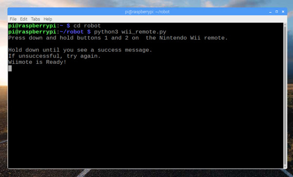
Power up your Raspberry Pi, and go to a terminal window. Open the robot directory:
cd robot
Run the wii_remote.py program.
python3 wii_remote.py
Press down the 1 and 2 buttons on the Wii remote at the same time and hold until you get a message that a Bluetooth connection has been made between the Raspberry Pi and the Wii remote control.
Bluetooth can be tricky to deal with on the Raspberry Pi, so if you fail to make the Bluetooth connection immediately, try again. Try to press and hold down 1 and 2 as soon as you run the code.
Once a connection has been made and assuming your robot is on the floor, press the arrow buttons on the remote control to drive your robot around.
The B button (trigger finger) enables you to stop the robot.
Typing CTRL – C in the terminal window stops the program.
Typing sudo shutdown – h now shuts off the Raspberry Pi. It is good practice to wait five seconds after you type this command before disconnecting the Rapberry Pi’s power.
To restart the Raspberry Pi, you just need to plug it into a power supply again.
Controlling the Speed of the Robot
You can control the speed of the robot by entering a number between 0 and 1 in the parentheses of the code I presented in the previous section. 0.50, for example, means 50% of full speed.
robot.forward(0.50)
GPIO pins in the Raspberry Pi can only be in two states, ON (+3.3 V) or OFF (0 V). By using a procedure known as pulse-width modulation (PWM), the GPIO pins switch ON and OFF so fast that the motor only perceives the average voltage. This technique enables the motor to have variable speeds as opposed to just two speeds (full speed and no speed at all).
We can also use the accelerometers of the Nintendo Wii remote to control the speed and direction of the robot. An accelerometer measures acceleration. And since the robot moves on only one plane, the x-y plane, we can move the Nintendo Wii remote forwards and backwards, and get the robot to respond to those actions.
For example, we can pitch the Wii remote forward (in the positive x-direction) to get the robot to move faster in the forward direction.
To make this happen, write the following program on your Raspberry Pi, and save it to your robot directory. You can name it wii_remote_variable.py.
import gpiozero  # GPIO Zero library
import cwiid  # Wii library

# File name: wii_remote_variable.py
# Code source (Matt-Timmons Brown): https://github.com/the-raspberry-pi-guy/raspirobots
# Date created: 5/27/2019
# Python version: 3.5.3
# Description: This program enables the
# Nintendo Wii remote control to make a robot
# move forwards, backwards, to the
# right, to the left using the accelerometer.

# Create a Robot object that is attached to
# GPIO pins 17, 18, 22, and 27 of the
# Raspberry Pi. These pins are inputs for the
# L293D motor controller.
robot = gpiozero.Robot(left=(22,27), right=(17,18))

print("Press down and hold buttons 1 and 2 on",
      " the Nintendo Wii remote.")
print(" ")
print("Hold down until you see a success message.")
print("If unsuccessful, try again.")

# Create a Wiimote object and assign it to the
# variable named wii. Bluetooth handshake
# is performed between the Wii remote
# and the Raspberry Pi
wii = cwiid.Wiimote()

print("Wiimote is Ready!")

# Turn on Wiimote reporting to enable the Python
# code to receive input from the Wiimote.
wii.rpt_mode = cwiid.RPT_BTN | cwiid.RPT_ACC

while True:
  # Store the x and y values of the accelerometer
  # into variables and scale to a number between
  # 95 and 145 and then -25 and 25. Negative
  # numbers mean backwards movement.
  x = (wii.state["acc"][cwiid.X] - 95) - 25
  y = (wii.state["acc"][cwiid.Y] - 95) - 25

  # Error checking to keep values in the interval
  # -25 to 25
  if x < -25:
    x = -25
  if y < -25:
    y = -25
  if x > 25:
    x = 25
  if y > 25:
    y = 25

  # Calculate a forward and turn value between -1
  # and 1
  forward_value = (float(x)/50)*2
  turn_value = (float(y)/50)*2

  # This code ensures the robot is not impacted
  # by slight movements in the remote control
  if (turn_value < 0.3) and (turn_value > -0.3):
    robot.value = (forward_value, forward_value)
  else:
    robot.value = (-turn_value, turn_value)
By holding the remote control sideways, with the Nintendo Wii’s direction pad (the cross on the remote) on your left, you can tilt and pitch the robot to move like you want it to.
Run the program (make sure the Raspberry Pi is not plugged in to a wall outlet, but rather the battery pack) by typing in the following command while inside your Raspberry Pi’s robot directory:
python3 wii_remote_variable.py
That’s it! At this point, your robot should be responding to your actions on the remote control. Move it forward, pitch it backward, and observe how your robot responds!
Press CTRL-C at any time in the terminal to stop the program.