In this tutorial, I will guide you through the process of creating a custom launch file to launch a robotic arm and a mobile robot in RViz.
RViz (short for “ROS Visualization”) is a 3D visualization tool for robots that allows you to view the robot’s sensors, environment, and state. I use it all the time to visualize and debug my robots.
Launch files in ROS 2 are powerful tools that allow you to start multiple nodes and set parameters with a single command, simplifying the process of managing your robot’s complex systems.
Prerequisites
- You have completed this tutorial: Create and Visualize a Mobile Robot with URDF – ROS 2 Jazzy
- I am assuming you are using Visual Studio Code, but you can use any code editor.
All my code for this project is located here on GitHub (robotic arm) and here on GitHub (mobile robot).
Create the Launch File for the Robotic Arm
Open a terminal window.
Move to your robotic arm directory.
cd ~/ros2_ws/src/mycobot_ros2/mycobot_description/ && mkdir launch && cd launchAdd a file in the launch folder called robot_state_publisher.launch.py.
Add this code.
#!/usr/bin/env python3
#
# Author: Addison Sears-Collins
# Date: November 10, 2024
# Description: Display the robotic arm with RViz
#
# This file launches the robot state publisher, joint state publisher,
# and RViz2 for visualizing the mycobot robot.

from launch import LaunchDescription
from launch.actions import DeclareLaunchArgument
from launch.conditions import IfCondition, UnlessCondition
from launch.substitutions import Command, LaunchConfiguration, PathJoinSubstitution
from launch_ros.actions import Node
from launch_ros.parameter_descriptions import ParameterValue
from launch_ros.substitutions import FindPackageShare

# Define the arguments for the XACRO file
ARGUMENTS = [
    DeclareLaunchArgument('prefix', default_value='',
                          description='Prefix for robot joints and links'),
    DeclareLaunchArgument('add_world', default_value='true',
                          choices=['true', 'false'],
                          description='Whether to add world link'),
    DeclareLaunchArgument('base_link', default_value='base_link',
                          description='Name of the base link'),
    DeclareLaunchArgument('base_type', default_value='g_shape',
                          description='Type of the base'),
    DeclareLaunchArgument('flange_link', default_value='link6_flange',
                          description='Name of the flange link'),
    DeclareLaunchArgument('gripper_type', default_value='adaptive_gripper',
                          description='Type of the gripper'),
    DeclareLaunchArgument('use_gazebo', default_value='false',
                          choices=['true', 'false'],
                          description='Whether to use Gazebo simulation'),
    DeclareLaunchArgument('use_gripper', default_value='true',
                          choices=['true', 'false'],
                          description='Whether to attach a gripper')
]


def generate_launch_description():
    # Define filenames
    urdf_package = 'mycobot_description'
    urdf_filename = 'mycobot_280.urdf.xacro'
    rviz_config_filename = 'mycobot_280_description.rviz'

    # Set paths to important files
    pkg_share_description = FindPackageShare(urdf_package)
    default_urdf_model_path = PathJoinSubstitution(
        [pkg_share_description, 'urdf', 'robots', urdf_filename])
    default_rviz_config_path = PathJoinSubstitution(
        [pkg_share_description, 'rviz', rviz_config_filename])

    # Launch configuration variables
    jsp_gui = LaunchConfiguration('jsp_gui')
    rviz_config_file = LaunchConfiguration('rviz_config_file')
    urdf_model = LaunchConfiguration('urdf_model')
    use_rviz = LaunchConfiguration('use_rviz')
    use_sim_time = LaunchConfiguration('use_sim_time')

    # Declare the launch arguments
    declare_jsp_gui_cmd = DeclareLaunchArgument(
        name='jsp_gui',
        default_value='true',
        choices=['true', 'false'],
        description='Flag to enable joint_state_publisher_gui')

    declare_rviz_config_file_cmd = DeclareLaunchArgument(
        name='rviz_config_file',
        default_value=default_rviz_config_path,
        description='Full path to the RVIZ config file to use')

    declare_urdf_model_path_cmd = DeclareLaunchArgument(
        name='urdf_model',
        default_value=default_urdf_model_path,
        description='Absolute path to robot urdf file')

    declare_use_rviz_cmd = DeclareLaunchArgument(
        name='use_rviz',
        default_value='true',
        description='Whether to start RVIZ')

    declare_use_sim_time_cmd = DeclareLaunchArgument(
        name='use_sim_time',
        default_value='false',
        description='Use simulation (Gazebo) clock if true')

    robot_description_content = ParameterValue(Command([
        'xacro', ' ', urdf_model, ' ',
        'prefix:=', LaunchConfiguration('prefix'), ' ',
        'add_world:=', LaunchConfiguration('add_world'), ' ',
        'base_link:=', LaunchConfiguration('base_link'), ' ',
        'base_type:=', LaunchConfiguration('base_type'), ' ',
        'flange_link:=', LaunchConfiguration('flange_link'), ' ',
        'gripper_type:=', LaunchConfiguration('gripper_type'), ' ',
        'use_gazebo:=', LaunchConfiguration('use_gazebo'), ' ',
        'use_gripper:=', LaunchConfiguration('use_gripper')
    ]), value_type=str)

    # Subscribe to the joint states of the robot, and publish the 3D pose of each link.
    start_robot_state_publisher_cmd = Node(
        package='robot_state_publisher',
        executable='robot_state_publisher',
        name='robot_state_publisher',
        output='screen',
        parameters=[{
            'use_sim_time': use_sim_time,
            'robot_description': robot_description_content}])

    # Publish the joint state values for the non-fixed joints in the URDF file.
    start_joint_state_publisher_cmd = Node(
        package='joint_state_publisher',
        executable='joint_state_publisher',
        name='joint_state_publisher',
        parameters=[{'use_sim_time': use_sim_time}],
        condition=UnlessCondition(jsp_gui))

    # Depending on gui parameter, either launch joint_state_publisher or joint_state_publisher_gui
    start_joint_state_publisher_gui_cmd = Node(
        package='joint_state_publisher_gui',
        executable='joint_state_publisher_gui',
        name='joint_state_publisher_gui',
        parameters=[{'use_sim_time': use_sim_time}],
        condition=IfCondition(jsp_gui))

    # Launch RViz
    start_rviz_cmd = Node(
        condition=IfCondition(use_rviz),
        package='rviz2',
        executable='rviz2',
        name='rviz2',
        output='screen',
        arguments=['-d', rviz_config_file],
        parameters=[{'use_sim_time': use_sim_time}])

    # Create the launch description and populate
    ld = LaunchDescription(ARGUMENTS)

    # Declare the launch options
    ld.add_action(declare_jsp_gui_cmd)
    ld.add_action(declare_rviz_config_file_cmd)
    ld.add_action(declare_urdf_model_path_cmd)
    ld.add_action(declare_use_rviz_cmd)
    ld.add_action(declare_use_sim_time_cmd)

    # Add any actions
    ld.add_action(start_joint_state_publisher_cmd)
    ld.add_action(start_joint_state_publisher_gui_cmd)
    ld.add_action(start_robot_state_publisher_cmd)
    ld.add_action(start_rviz_cmd)

    return ld
Create the Launch File for the Mobile Robot
Open a terminal window.
Move to your mobile robot directory.
cd ~/ros2_ws/src/yahboom_rosmaster/yahboom_rosmaster_description/ && mkdir launch && cd launchAdd a file in the launch folder called robot_state_publisher.launch.py.
Add this code.
#!/usr/bin/env python3
#
# Author: Addison Sears-Collins
# Date: November 11, 2024
# Description: Display the Yahboom (ROSMASTER) robot in RViz
#
# This file launches the robot state publisher, joint state publisher,
# and RViz2 for visualizing the ROSMASTER robot.
from launch import LaunchDescription
from launch.actions import DeclareLaunchArgument
from launch.conditions import IfCondition, UnlessCondition
from launch.substitutions import Command, LaunchConfiguration, PathJoinSubstitution
from launch_ros.actions import Node
from launch_ros.parameter_descriptions import ParameterValue
from launch_ros.substitutions import FindPackageShare
# Define the arguments for the XACRO file
ARGUMENTS = [
DeclareLaunchArgument('prefix', default_value='',
description='Prefix for robot joints and links'),
DeclareLaunchArgument('use_gazebo', default_value='false',
choices=['true', 'false'],
description='Whether to use Gazebo simulation')
]
def generate_launch_description():
# Define filenames
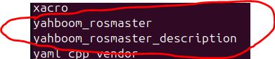
urdf_package = 'yahboom_rosmaster_description'
urdf_filename = 'rosmaster_x3.urdf.xacro'
rviz_config_filename = 'yahboom_rosmaster_description.rviz'
# Set paths to important files
pkg_share_description = FindPackageShare(urdf_package)
default_urdf_model_path = PathJoinSubstitution(
[pkg_share_description, 'urdf', 'robots', urdf_filename])
default_rviz_config_path = PathJoinSubstitution(
[pkg_share_description, 'rviz', rviz_config_filename])
# Launch configuration variables
jsp_gui = LaunchConfiguration('jsp_gui')
rviz_config_file = LaunchConfiguration('rviz_config_file')
urdf_model = LaunchConfiguration('urdf_model')
use_rviz = LaunchConfiguration('use_rviz')
use_sim_time = LaunchConfiguration('use_sim_time')
# Declare the launch arguments
declare_jsp_gui_cmd = DeclareLaunchArgument(
name='jsp_gui',
default_value='true',
choices=['true', 'false'],
description='Flag to enable joint_state_publisher_gui')
declare_rviz_config_file_cmd = DeclareLaunchArgument(
name='rviz_config_file',
default_value=default_rviz_config_path,
description='Full path to the RVIZ config file to use')
declare_urdf_model_path_cmd = DeclareLaunchArgument(
name='urdf_model',
default_value=default_urdf_model_path,
description='Absolute path to robot urdf file')
declare_use_rviz_cmd = DeclareLaunchArgument(
name='use_rviz',
default_value='true',
description='Whether to start RVIZ')
declare_use_sim_time_cmd = DeclareLaunchArgument(
name='use_sim_time',
default_value='false',
description='Use simulation (Gazebo) clock if true')
robot_description_content = ParameterValue(Command([
'xacro', ' ', urdf_model, ' ',
'prefix:=', LaunchConfiguration('prefix'), ' ',
'use_gazebo:=', LaunchConfiguration('use_gazebo')
]), value_type=str)
# Subscribe to the joint states of the robot, and publish the 3D pose of each link.
start_robot_state_publisher_cmd = Node(
package='robot_state_publisher',
executable='robot_state_publisher',
name='robot_state_publisher',
output='screen',
parameters=[{
'use_sim_time': use_sim_time,
'robot_description': robot_description_content}])
# Publish the joint state values for the non-fixed joints in the URDF file.
start_joint_state_publisher_cmd = Node(
package='joint_state_publisher',
executable='joint_state_publisher',
name='joint_state_publisher',
parameters=[{'use_sim_time': use_sim_time}],
condition=UnlessCondition(jsp_gui))
# Depending on gui parameter, either launch joint_state_publisher or joint_state_publisher_gui
start_joint_state_publisher_gui_cmd = Node(
package='joint_state_publisher_gui',
executable='joint_state_publisher_gui',
name='joint_state_publisher_gui',
parameters=[{'use_sim_time': use_sim_time}],
condition=IfCondition(jsp_gui))
# Launch RViz
start_rviz_cmd = Node(
condition=IfCondition(use_rviz),
package='rviz2',
executable='rviz2',
output='screen',
arguments=['-d', rviz_config_file],
parameters=[{'use_sim_time': use_sim_time}])
# Create the launch description and populate
ld = LaunchDescription(ARGUMENTS)
# Declare the launch options
ld.add_action(declare_jsp_gui_cmd)
ld.add_action(declare_rviz_config_file_cmd)
ld.add_action(declare_urdf_model_path_cmd)
ld.add_action(declare_use_rviz_cmd)
ld.add_action(declare_use_sim_time_cmd)
# Add any actions
ld.add_action(start_joint_state_publisher_cmd)
ld.add_action(start_joint_state_publisher_gui_cmd)
ld.add_action(start_robot_state_publisher_cmd)
ld.add_action(start_rviz_cmd)
return ld
Add the RViz Configuration File
Now that we have written our launch file, let’s add the RViz configuration file.
cd ~/ros2_ws/src/mycobot_ros2/mycobot_description/ && mkdir rviz && cd rvizCreate a file named mycobot_280_description.rviz.
Add this code.
cd ~/ros2_ws/src/yahboom_rosmaster/yahboom_rosmaster_description/ && mkdir rviz && cd rvizCreate a file named yahboom_rosmaster_description.rviz
Add this code.
You don’t need to understand all the nitty gritty details of this configuration file. You can generate one automatically through RViz.
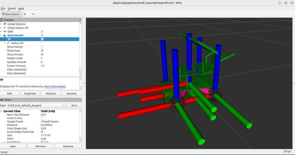
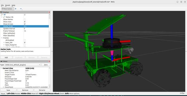
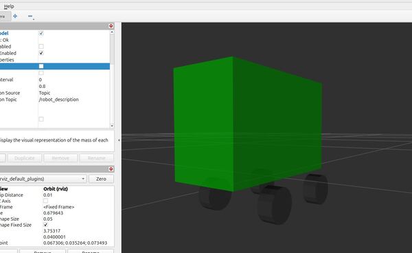
On a high-level, RViz configuration files end with the extension .rviz. These files set up an RViz configuration with a grid, a robot model, and coordinate frame visualizations.
This configuration file also enables the camera movement tool and sets the initial camera view to an orbit view, which allows orbiting around a focal point in the scene.
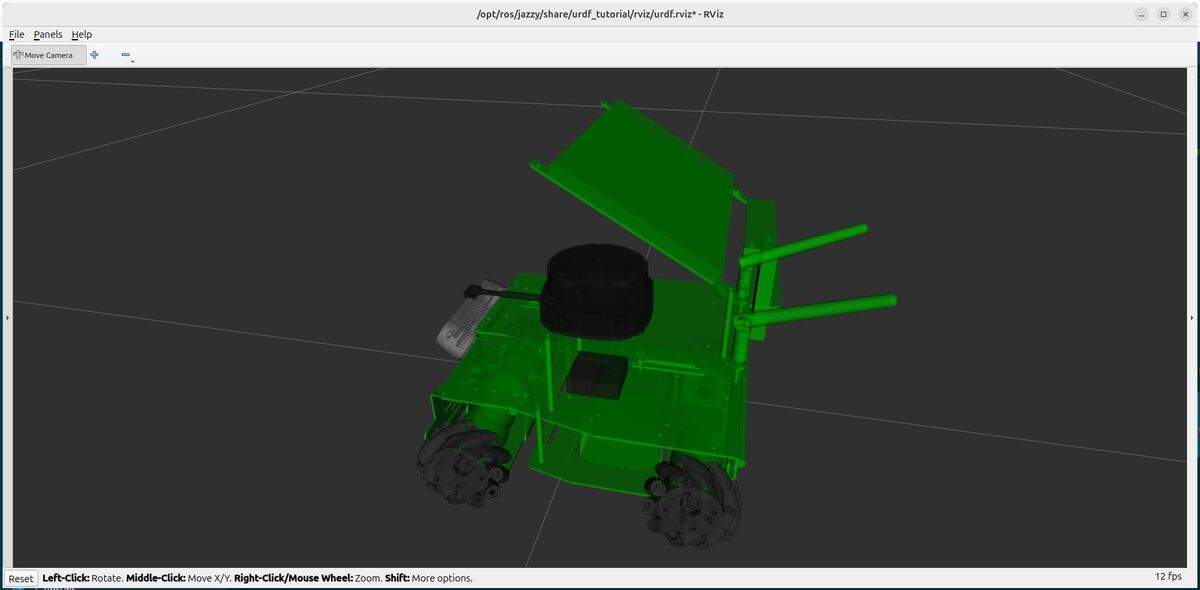
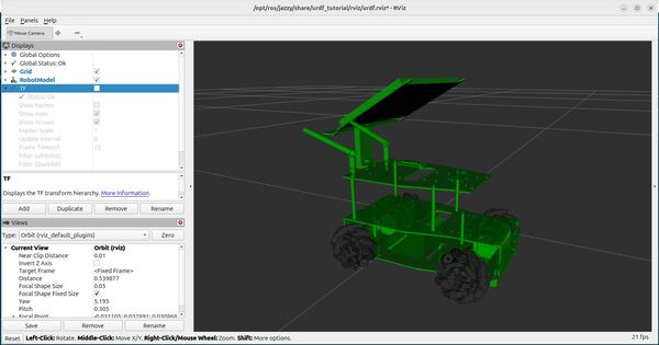
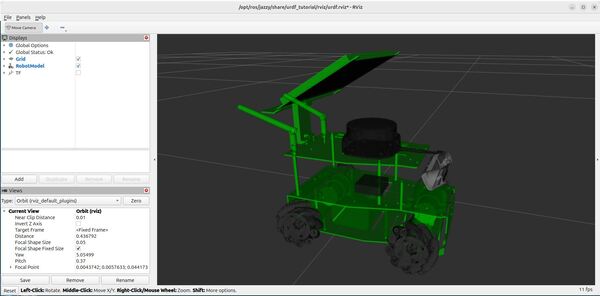
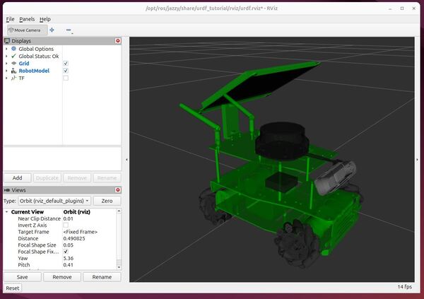
When RViz is launched with this configuration file, it will display the robot model and allow interaction and visualization of the robot.
Edit CMakeLists.txt
Now we need to edit CMakeLists.txt so the build system can find our new folders, launch and rviz.
cd ~/ros2_ws/src/mycobot_ros2/mycobot_description/ gedit CMakeLists.txtAdd this code:
# Copy necessary files to designated locations in the project
install (
  DIRECTORY launch meshes urdf rviz
  DESTINATION share/${PROJECT_NAME}
)
cd ~/ros2_ws/src/yahboom_rosmaster/yahboom_rosmaster_description/ gedit CMakeLists.txtAdd this code:
# Copy necessary files to designated locations in the project
install (
  DIRECTORY launch meshes urdf rviz
  DESTINATION share/${PROJECT_NAME}
)
Save the file, and close it.
Now build your workspace.
cd ~/ros2_ws/colcon buildsource ~/.bashrcLaunch the Launch Files
Launch your launch files:
ros2 launch mycobot_description robot_state_publisher.launch.py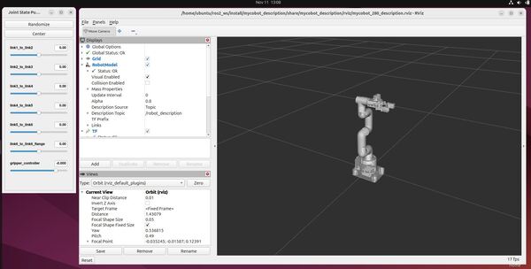
ros2 launch yahboom_rosmaster_description robot_state_publisher.launch.pyYou can also add launch arguments. To see the available launch arguments, type:
ros2 launch mycobot_description robot_state_publisher.launch.py --show-argsFor example, to disable the gripper, type:
ros2 launch mycobot_description robot_state_publisher.launch.py use_gripper:=falseTo add a prefix to the robot (e.g. left arm of a dual arm robot), type:
ros2 launch mycobot_description robot_state_publisher.launch.py use_gripper:=false prefix:=left_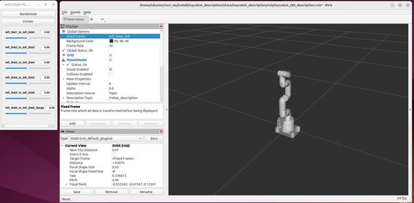
If you want to launch the robots with no GUIs, do this:
ros2 launch mycobot_description robot_state_publisher.launch.py jsp_gui:=false use_rviz:=falseros2 launch yahboom_rosmaster_description robot_state_publisher.launch.py jsp_gui:=false use_rviz:=false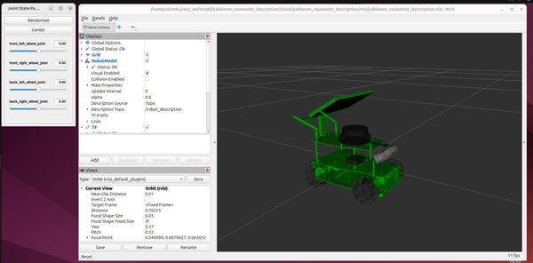
And there you have it…your first custom launch files.
Launch File Walkthrough
Let’s walk through this ROS 2 launch file that visualizes a robotic arm in RViz.
Starting with the imports, we bring in essential ROS 2 launch utilities.
from launch import LaunchDescription
from launch.actions import DeclareLaunchArgument
from launch.conditions import IfCondition, UnlessCondition
The launch file’s core purpose is orchestrating multiple nodes – think of it as a conductor coordinating different musicians in an orchestra. Here, our musicians are:
- Robot State Publisher: Broadcasts the robot’s current pose
- Joint State Publisher: Manages the robot’s joint positions
- RViz: Provides the 3D visualization
The ARGUMENTS list defines the robot’s configurable parameters:
ARGUMENTS = [
    DeclareLaunchArgument('prefix', default_value='',
                          description='Prefix for robot joints and links'),
    DeclareLaunchArgument('add_world', default_value='true',
                          description='Whether to add world link'),
    # ... other arguments
]
These arguments allow users to customize the robot’s configuration without changing the code – like using command-line switches to modify a program’s behavior.
The generate_launch_description() function is where the magic happens. First, it sets up the file paths:
urdf_package = 'mycobot_description'
urdf_filename = 'mycobot_280.urdf.xacro'
rviz_config_filename = 'mycobot_280_description.rviz'
The robot’s description is loaded from a XACRO file (an XML macro file) and converted into a robot_description parameter:
robot_description_content = ParameterValue(Command([
    'xacro', ' ', urdf_model, ' ',
    'prefix:=', LaunchConfiguration('prefix'),
    # ... other parameters
]), value_type=str)
Then we create three key nodes:
1. Robot State Publisher:
start_robot_state_publisher_cmd = Node(
    package='robot_state_publisher',
    executable='robot_state_publisher',
    name='robot_state_publisher',
    output='screen',
    parameters=[{
        'use_sim_time': use_sim_time,
        'robot_description': robot_description_content}])
This node takes the robot description and joint states and publishes the 3D poses of all robot links – like a GPS system for each part of the robot.
2. Joint State Publisher (with optional GUI):
start_joint_state_publisher_cmd = Node(
    package='joint_state_publisher',
    executable='joint_state_publisher',
    name='joint_state_publisher',
    parameters=[{'use_sim_time': use_sim_time}],
    condition=UnlessCondition(jsp_gui))
This publishes joint positions – imagine it as the robot’s muscle control center. The GUI version allows manual control of these joints.
3. RViz:
start_rviz_cmd = Node(
    condition=IfCondition(use_rviz),
    package='rviz2',
    executable='rviz2',
    name='rviz2',
    output='screen',
    arguments=['-d', rviz_config_file])
This is our visualization tool, loading a pre-configured layout specified in the RViz config file.
Finally, everything is assembled into a LaunchDescription and returned:
ld = LaunchDescription(ARGUMENTS)
# Add all the actions...
return ld
This launch file structure is common in ROS 2 applications, providing a clean way to start multiple nodes simultaneously.
That’s it.
Keep building, and I will see you in the next tutorial!