
In this tutorial, I will show you how to move a robot around a room remotely, from your own PC. Being able to control a robot’s velocity remotely is useful for a number of use cases, such as building a map, exploring an unknown environment, or getting to hard-to-reach environments.
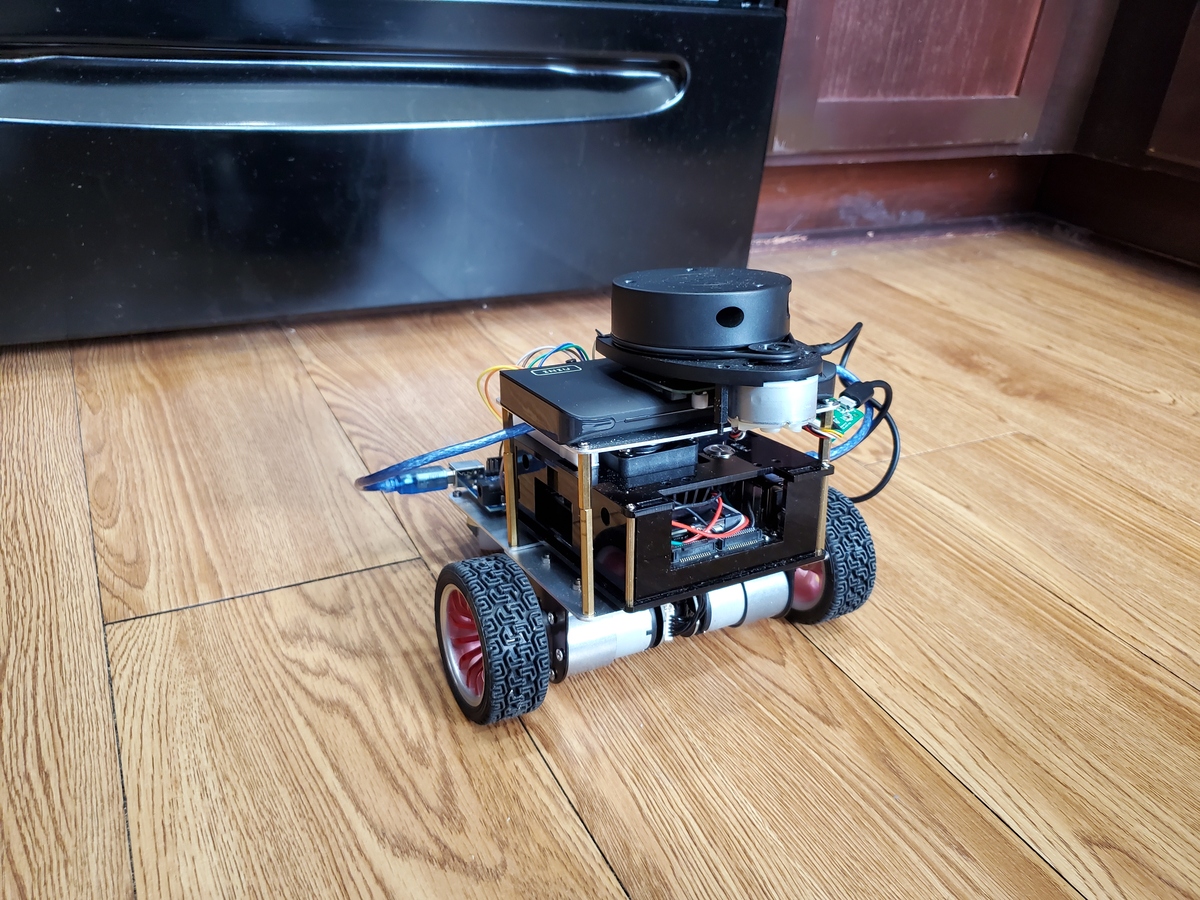
By the end of this tutorial, you will be able to send velocity commands to an Arduino microcontroller from your PC. Arduino will then convert those velocity commands into output PWM signals to drive the motors of a two-wheeled differential robot like the one on this post.
Real-World Applications
This project has a number of real-world applications:
- Indoor Delivery Robots
- Room Service Robots
- Mapping of Underground Mines, Caves, and Hard-to-Reach Environments
- Robot Vacuums
- Order Fulfillment
- Factories
Prerequisites
- You have already set up your NVIDIA Jetson Nano (4GB, B01) with ROS. You can also use an Ubuntu-enabled Raspberry Pi that has ROS installed.
- You have installed the software that enables ROS to speak with an Arduino.
- We will continue from the launch file I worked on in this post, or you can start a brand new one.
- You have a robot (optional). I will continue with my two-wheeled differential drive robot.
Set Up the Hardware
This tutorial here shows you how to set up the motors.
Write the Code
Open the Arduino IDE, and write the following program. The name of my program is motor_controller_diff_drive_2.ino. It builds from the tick_publisher.ino program I wrote in an earlier post.
/*
 * Author: Automatic Addison
 * Website: https://automaticaddison.com
 * Description: ROS node that publishes the accumulated ticks for each wheel
 * (/right_ticks and /left_ticks topics) at regular intervals using the
 * built-in encoder (forward = positive; reverse = negative).
 * The node also subscribes to linear & angular velocity commands published on
 * the /cmd_vel topic to drive the robot accordingly.
 * Reference: Practical Robotics in C++ book (ISBN-10 : 9389423465)
 */

#include <ros.h>
#include <std_msgs/Int16.h>
#include <geometry_msgs/Twist.h>

// Handles startup and shutdown of ROS
ros::NodeHandle nh;

////////////////// Tick Data Publishing Variables and Constants ///////////////

// Encoder output to Arduino Interrupt pin. Tracks the tick count.
#define ENC_IN_LEFT_A 2
#define ENC_IN_RIGHT_A 3

// Other encoder output to Arduino to keep track of wheel direction
// Tracks the direction of rotation.
#define ENC_IN_LEFT_B 4
#define ENC_IN_RIGHT_B 11

// True = Forward; False = Reverse
boolean Direction_left = true;
boolean Direction_right = true;

// Minumum and maximum values for 16-bit integers
// Range of 65,535
const int encoder_minimum = -32768;
const int encoder_maximum = 32767;

// Keep track of the number of wheel ticks
std_msgs::Int16 right_wheel_tick_count;
ros::Publisher rightPub("right_ticks", &right_wheel_tick_count);

std_msgs::Int16 left_wheel_tick_count;
ros::Publisher leftPub("left_ticks", &left_wheel_tick_count);

// Time interval for measurements in milliseconds
const int interval = 30;
long previousMillis = 0;
long currentMillis = 0;

////////////////// Motor Controller Variables and Constants ///////////////////

// Motor A connections
const int enA = 9;
const int in1 = 5;
const int in2 = 6;

// Motor B connections
const int enB = 10;
const int in3 = 7;
const int in4 = 8;

// How much the PWM value can change each cycle
const int PWM_INCREMENT = 1;

// Number of ticks per wheel revolution. We won't use this in this code.
const int TICKS_PER_REVOLUTION = 620;

// Wheel radius in meters
const double WHEEL_RADIUS = 0.033;

// Distance from center of the left tire to the center of the right tire in m
const double WHEEL_BASE = 0.17;

// Number of ticks a wheel makes moving a linear distance of 1 meter
// This value was measured manually.
const double TICKS_PER_METER = 3100; // Originally 2880

// Proportional constant, which was measured by measuring the
// PWM-Linear Velocity relationship for the robot.
const int K_P = 278;

// Y-intercept for the PWM-Linear Velocity relationship for the robot
const int b = 52;

// Correction multiplier for drift. Chosen through experimentation.
const int DRIFT_MULTIPLIER = 120;

// Turning PWM output (0 = min, 255 = max for PWM values)
const int PWM_TURN = 80;

// Set maximum and minimum limits for the PWM values
const int PWM_MIN = 80; // about 0.1 m/s
const int PWM_MAX = 100; // about 0.172 m/s

// Set linear velocity and PWM variable values for each wheel
double velLeftWheel = 0;
double velRightWheel = 0;
double pwmLeftReq = 0;
double pwmRightReq = 0;

// Record the time that the last velocity command was received
double lastCmdVelReceived = 0;

/////////////////////// Tick Data Publishing Functions ////////////////////////

// Increment the number of ticks
void right_wheel_tick() {

  // Read the value for the encoder for the right wheel
  int val = digitalRead(ENC_IN_RIGHT_B);

  if (val == LOW) {
    Direction_right = false; // Reverse
  }
  else {
    Direction_right = true; // Forward
  }

  if (Direction_right) {

    if (right_wheel_tick_count.data == encoder_maximum) {
      right_wheel_tick_count.data = encoder_minimum;
    }
    else {
      right_wheel_tick_count.data++;
    }
  }
  else {
    if (right_wheel_tick_count.data == encoder_minimum) {
      right_wheel_tick_count.data = encoder_maximum;
    }
    else {
      right_wheel_tick_count.data--;
    }
  }
}

// Increment the number of ticks
void left_wheel_tick() {

  // Read the value for the encoder for the left wheel
  int val = digitalRead(ENC_IN_LEFT_B);

  if (val == LOW) {
    Direction_left = true; // Reverse
  }
  else {
    Direction_left = false; // Forward
  }

  if (Direction_left) {
    if (left_wheel_tick_count.data == encoder_maximum) {
      left_wheel_tick_count.data = encoder_minimum;
    }
    else {
      left_wheel_tick_count.data++;
    }
  }
  else {
    if (left_wheel_tick_count.data == encoder_minimum) {
      left_wheel_tick_count.data = encoder_maximum;
    }
    else {
      left_wheel_tick_count.data--;
    }
  }
}

/////////////////////// Motor Controller Functions ////////////////////////////

// Calculate the left wheel linear velocity in m/s every time a
// tick count message is rpublished on the /left_ticks topic.
void calc_vel_left_wheel(){

  // Previous timestamp
  static double prevTime = 0;

  // Variable gets created and initialized the first time a function is called.
  static int prevLeftCount = 0;

  // Manage rollover and rollunder when we get outside the 16-bit integer range
  int numOfTicks = (65535 + left_wheel_tick_count.data - prevLeftCount) % 65535;

  // If we have had a big jump, it means the tick count has rolled over.
  if (numOfTicks > 10000) {
        numOfTicks = 0 - (65535 - numOfTicks);
  }

  // Calculate wheel velocity in meters per second
  velLeftWheel = numOfTicks/TICKS_PER_METER/((millis()/1000)-prevTime);

  // Keep track of the previous tick count
  prevLeftCount = left_wheel_tick_count.data;

  // Update the timestamp
  prevTime = (millis()/1000);

}

// Calculate the right wheel linear velocity in m/s every time a
// tick count message is published on the /right_ticks topic.
void calc_vel_right_wheel(){

  // Previous timestamp
  static double prevTime = 0;

  // Variable gets created and initialized the first time a function is called.
  static int prevRightCount = 0;

  // Manage rollover and rollunder when we get outside the 16-bit integer range
  int numOfTicks = (65535 + right_wheel_tick_count.data - prevRightCount) % 65535;

  if (numOfTicks > 10000) {
        numOfTicks = 0 - (65535 - numOfTicks);
  }

  // Calculate wheel velocity in meters per second
  velRightWheel = numOfTicks/TICKS_PER_METER/((millis()/1000)-prevTime);

  prevRightCount = right_wheel_tick_count.data;

  prevTime = (millis()/1000);

}

// Take the velocity command as input and calculate the PWM values.
void calc_pwm_values(const geometry_msgs::Twist& cmdVel) {

  // Record timestamp of last velocity command received
  lastCmdVelReceived = (millis()/1000);

  // Calculate the PWM value given the desired velocity
  pwmLeftReq = K_P * cmdVel.linear.x + b;
  pwmRightReq = K_P * cmdVel.linear.x + b;

  // Check if we need to turn
  if (cmdVel.angular.z != 0.0) {

    // Turn left
    if (cmdVel.angular.z > 0.0) {
      pwmLeftReq = -PWM_TURN;
      pwmRightReq = PWM_TURN;
    }
    // Turn right
    else {
      pwmLeftReq = PWM_TURN;
      pwmRightReq = -PWM_TURN;
    }
  }
  // Go straight
  else {

    // Remove any differences in wheel velocities
    // to make sure the robot goes straight
    static double prevDiff = 0;
    static double prevPrevDiff = 0;
    double currDifference = velLeftWheel - velRightWheel;
    double avgDifference = (prevDiff+prevPrevDiff+currDifference)/3;
    prevPrevDiff = prevDiff;
    prevDiff = currDifference;

    // Correct PWM values of both wheels to make the vehicle go straight
    pwmLeftReq -= (int)(avgDifference * DRIFT_MULTIPLIER);
    pwmRightReq += (int)(avgDifference * DRIFT_MULTIPLIER);
  }

  // Handle low PWM values
  if (abs(pwmLeftReq) < PWM_MIN) {
    pwmLeftReq = 0;
  }
  if (abs(pwmRightReq) < PWM_MIN) {
    pwmRightReq = 0;
  }
}

void set_pwm_values() {

  // These variables will hold our desired PWM values
  static int pwmLeftOut = 0;
  static int pwmRightOut = 0;

  // If the required PWM is of opposite sign as the output PWM, we want to
  // stop the car before switching direction
  static bool stopped = false;
  if ((pwmLeftReq * velLeftWheel < 0 && pwmLeftOut != 0) ||
      (pwmRightReq * velRightWheel < 0 && pwmRightOut != 0)) {
    pwmLeftReq = 0;
    pwmRightReq = 0;
  }

  // Set the direction of the motors
  if (pwmLeftReq > 0) { // Left wheel forward
    digitalWrite(in1, HIGH);
    digitalWrite(in2, LOW);
  }
  else if (pwmLeftReq < 0) { // Left wheel reverse
    digitalWrite(in1, LOW);
    digitalWrite(in2, HIGH);
  }
  else if (pwmLeftReq == 0 && pwmLeftOut == 0 ) { // Left wheel stop
    digitalWrite(in1, LOW);
    digitalWrite(in2, LOW);
  }
  else { // Left wheel stop
    digitalWrite(in1, LOW);
    digitalWrite(in2, LOW);
  }

  if (pwmRightReq > 0) { // Right wheel forward
    digitalWrite(in3, HIGH);
    digitalWrite(in4, LOW);
  }
  else if(pwmRightReq < 0) { // Right wheel reverse
    digitalWrite(in3, LOW);
    digitalWrite(in4, HIGH);
  }
  else if (pwmRightReq == 0 && pwmRightOut == 0) { // Right wheel stop
    digitalWrite(in3, LOW);
    digitalWrite(in4, LOW);
  }
  else { // Right wheel stop
    digitalWrite(in3, LOW);
    digitalWrite(in4, LOW);
  }

  // Increase the required PWM if the robot is not moving
  if (pwmLeftReq != 0 && velLeftWheel == 0) {
    pwmLeftReq *= 1.5;
  }
  if (pwmRightReq != 0 && velRightWheel == 0) {
    pwmRightReq *= 1.5;
  }

  // Calculate the output PWM value by making slow changes to the current value
  if (abs(pwmLeftReq) > pwmLeftOut) {
    pwmLeftOut += PWM_INCREMENT;
  }
  else if (abs(pwmLeftReq) < pwmLeftOut) {
    pwmLeftOut -= PWM_INCREMENT;
  }
  else{}

  if (abs(pwmRightReq) > pwmRightOut) {
    pwmRightOut += PWM_INCREMENT;
  }
  else if(abs(pwmRightReq) < pwmRightOut) {
    pwmRightOut -= PWM_INCREMENT;
  }
  else{}

  // Conditional operator to limit PWM output at the maximum
  pwmLeftOut = (pwmLeftOut > PWM_MAX) ? PWM_MAX : pwmLeftOut;
  pwmRightOut = (pwmRightOut > PWM_MAX) ? PWM_MAX : pwmRightOut;

  // PWM output cannot be less than 0
  pwmLeftOut = (pwmLeftOut < 0) ? 0 : pwmLeftOut;
  pwmRightOut = (pwmRightOut < 0) ? 0 : pwmRightOut;

  // Set the PWM value on the pins
  analogWrite(enA, pwmLeftOut);
  analogWrite(enB, pwmRightOut);
}

// Set up ROS subscriber to the velocity command
ros::Subscriber<geometry_msgs::Twist> subCmdVel("cmd_vel", &calc_pwm_values );

void setup() {

  // Set pin states of the encoder
  pinMode(ENC_IN_LEFT_A , INPUT_PULLUP);
  pinMode(ENC_IN_LEFT_B , INPUT);
  pinMode(ENC_IN_RIGHT_A , INPUT_PULLUP);
  pinMode(ENC_IN_RIGHT_B , INPUT);

  // Every time the pin goes high, this is a tick
  attachInterrupt(digitalPinToInterrupt(ENC_IN_LEFT_A), left_wheel_tick, RISING);
  attachInterrupt(digitalPinToInterrupt(ENC_IN_RIGHT_A), right_wheel_tick, RISING);

  // Motor control pins are outputs
  pinMode(enA, OUTPUT);
  pinMode(enB, OUTPUT);
  pinMode(in1, OUTPUT);
  pinMode(in2, OUTPUT);
  pinMode(in3, OUTPUT);
  pinMode(in4, OUTPUT);

  // Turn off motors - Initial state
  digitalWrite(in1, LOW);
  digitalWrite(in2, LOW);
  digitalWrite(in3, LOW);
  digitalWrite(in4, LOW);

  // Set the motor speed
  analogWrite(enA, 0);
  analogWrite(enB, 0);

  // ROS Setup
  nh.getHardware()->setBaud(115200);
  nh.initNode();
  nh.advertise(rightPub);
  nh.advertise(leftPub);
  nh.subscribe(subCmdVel);
}

void loop() {

  nh.spinOnce();

  // Record the time
  currentMillis = millis();

  // If the time interval has passed, publish the number of ticks,
  // and calculate the velocities.
  if (currentMillis - previousMillis > interval) {

    previousMillis = currentMillis;

    // Publish tick counts to topics
    leftPub.publish( &left_wheel_tick_count );
    rightPub.publish( &right_wheel_tick_count );

    // Calculate the velocity of the right and left wheels
    calc_vel_right_wheel();
    calc_vel_left_wheel();

  }

  // Stop the car if there are no cmd_vel messages
  if((millis()/1000) - lastCmdVelReceived > 1) {
    pwmLeftReq = 0;
    pwmRightReq = 0;
  }

  set_pwm_values();
}
Upload the program to the Arduino. You might see a warning about low memory. Just ignore it.
Note that I set the minimum PWM value (i.e. motor speed) to 80 and the maximum to 100. These numbers might be different if you use other motors.
80 is really the ideal speed when you want to map an indoor environment (found through testing). The actual PWM range is 0 to 255, but we won’t want to get to either of these extremes.
The number of ticks per 1 full revolution of a wheel is 620.
Through testing I also found the following PWM value to speed (m/s relationships)
- 80 = 0.1 m/s
- 100 = 0.172 m/s
This yields an equation of:
PWM_Value = 277.78 * (Speed in m/s) + 52.22
Launch the Motor Controller
I will use the rqt_robot_steering interface that I used in this tutorial to publish Twist messages to the cmd_vel topic. A Twist message in ROS is a special kind of topic that consists of the x, y, and z components of the linear and angular velocity.
The only two velocity components we will use in this case is the linear velocity along the x-axis and the angular velocity around the z-axis. If you are not familiar with how 3D axes work in robotics, take a look at this post.
Arduino will read Twist messages that are published on the /cmd_vel topic.
Make sure your Arduino is plugged into the Jetson Nano.
Turn on your Jetson Nano.
Turn on the batteries for the motor.
Let’s test our motor controller.
Open a new terminal window, and launch ROS.
cd ~/catkin_ws
roscore
Open a new terminal window, and launch the ROS serial server.
rosrun rosserial_python serial_node.py _port:=/dev/ttyACM0 _baud:=115200
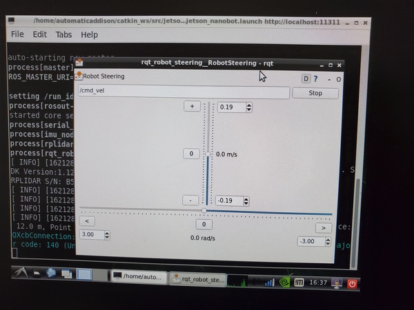
Open a new terminal window, and launch the rqt_robot_steering node so that we can send velocity commands to Arduino.
rosrun rqt_robot_steering rqt_robot_steering
Open a new terminal window, and check out the active topics.
rostopic list
Let’s check out the /cmd_vel topic.
rostopic echo /cmd_vel
Move the slider on the rqt_robot_steering GUI, and watch the /cmd_vel velocity commands change accordingly. Your robot should move accordingly.
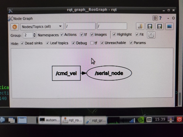
Check out the rqt graph. Open a new terminal window, and type:
rosrun rqt_graph rqt_graph
Run a Launch File (Optional)
Now, let’s add the rqt_robot_steering node to our mother launch file named jetson_nanobot.launch.
Go to the launch file.
roscd launch_jetson_nano_bot
cd launch
gedit jetson_nanobot.launch
Add the following lines below the Lidar data publisher node.
  <node pkg="rqt_robot_steering" type="rqt_robot_steering" name="rqt_robot_steering">
  </node>
Save the file, and close it.
Open a new terminal window, and go to the home directory.
cd
Launch the launch file.
roslaunch launch_jetson_nano_bot jetson_nanobot.launch
If you open a new terminal window, and type the following command, you will be able to see the active topics.
rostopic list
That’s it! Keep building.