In this post, we will learn the basics of ROS 2 by working with Turtlesim, a ROS 2-based simulator. Follow each step below, one line at a time. Take your time, so you do everything correctly. There is no hurry.
The official tutorial is located in the ROS 2 Foxy documentation, but we’ll run through the entire process step-by-step below.
You Will Need
In order to complete this tutorial, you will need:
Prerequisites
It is helpful if you’ve completed this tutorial on Linux fundamentals, but it is not required.
Install Turtlesim
Install Turtlesim, by typing the following commands:
sudo apt update
sudo apt install ros-foxy-turtlesim
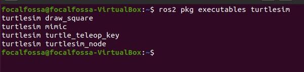
Check that Turtlesim was installed.
ros2 pkg executables turtlesim
Here is what you should see:
Launch Turtlesim
To launch Turtlesim, type:
ros2 run turtlesim turtlesim_node
Here is the window that you should see:
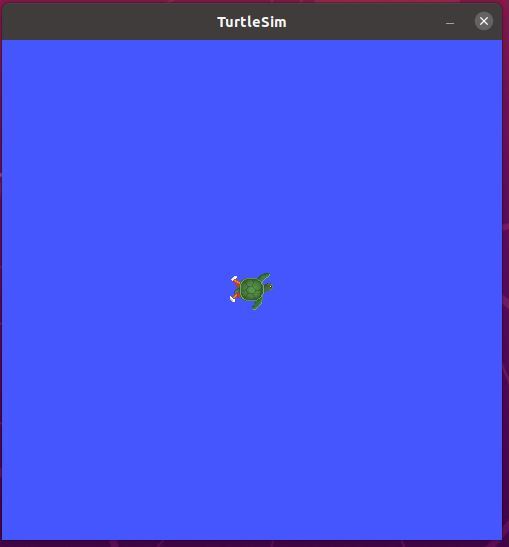
In the terminal, you will see the position and orientation of the turtle.

Let’s move the turtle around the blue screen.
ros2 run turtlesim turtle_teleop_key
With this same terminal window selected, use the arrow keys to navigate the turtle around the screen.
To close turtlesim, go to all terminal windows and type:
CTRL + C
Common ROS 2 Commands
Open a new terminal. Let’s type some common ROS 2 commands.
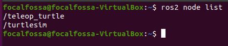
To list the active ROS nodes, type the following command. A node in ROS is just a program (e.g. typically a piece of source code made in C++ or Python) that does some computation.
ros2 node list
Robots require a number of programs to work together to achieve a task. You can think of a node as a small single-purpose program within a larger robotic system.
One way nodes communicate with each other is by using messages. These messages are passed via channels called topics.
To see a list of active topics in ROS 2, type the following command:
ros2 topic list
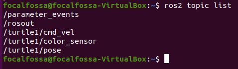
Don’t worry what all those topics mean. In a later post, I’ll dive deeper into ROS topics.
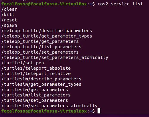
Let’s see what the active services are. A ROS Service consists of a pair of messages: one for the request and one for the reply. A service-providing ROS node (i.e. Service Server) offers a service (e.g. read sensor data).
ros2 service list
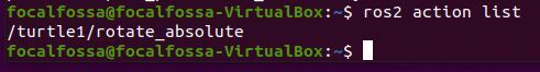
Let’s see what actions are active now. I explain the difference between a ROS Action and a ROS Service in this post.
ros2 action list
Here is one more command you should know:
- ros2 node info <node_name> : Shows information about the node named node_name.
Install rqt
Let’s install rqt. rqt is a tool that enables you to see the connections between nodes.
sudo apt update
sudo apt install ~nros-foxy-rqt*
Press Y and Enter to complete the installation.
Run rqt
Launch turtlesim again.
ros2 run turtlesim turtlesim_node
In another terminal tab, type:
ros2 run turtlesim turtle_teleop_key
To run rqt, open a terminal window and type:
rqt
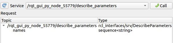
If this is your first time running rqt, go to Plugins > Services > Service Caller in the menu bar at the top.
Here is what my window looks like:
Click the refresh button to the left of the Service dropdown menu. This button looks like this:

Here is what my window looks like now:
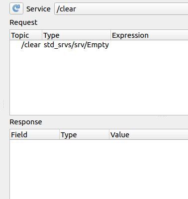
Click the dropdown list in the middle of the window, and select the /spawn service.
Launch Another Turtle Using the Spawn Service
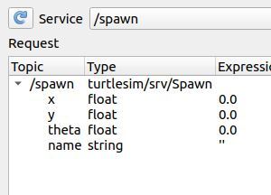
The /spawn service spawns another turtle. Let’s use this service now.
Set the values under the Request area to the following by double-clicking the values under the ‘Expression’ menu.
In this case, we want to launch a new turtle at coordinate x=1.0, y=1.0. The name of this new turtle will be turtle2.
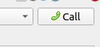
Call this service by clicking the Call button in the upper right of the panel.
You should see a new turtle spawned at coordinate x=1.0, y=1.0.
Click the Refresh button.
You now have new services for turtle2.
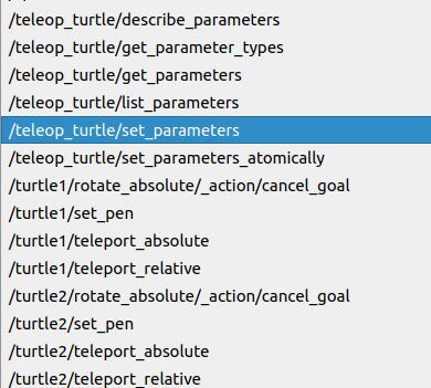
Using the Set Pen Service
Let’s change the color of the pen for the first turtle, turtle1.
Go to the Service dropdown list, and scroll down to /turtle1/set_pen.
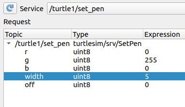
We want turtle1’s pen to be green, so we set the g (Green) color value to 255. I also want the width of the pen to be 5.
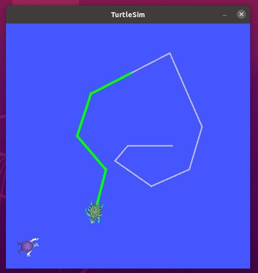
Click Call to call the service.
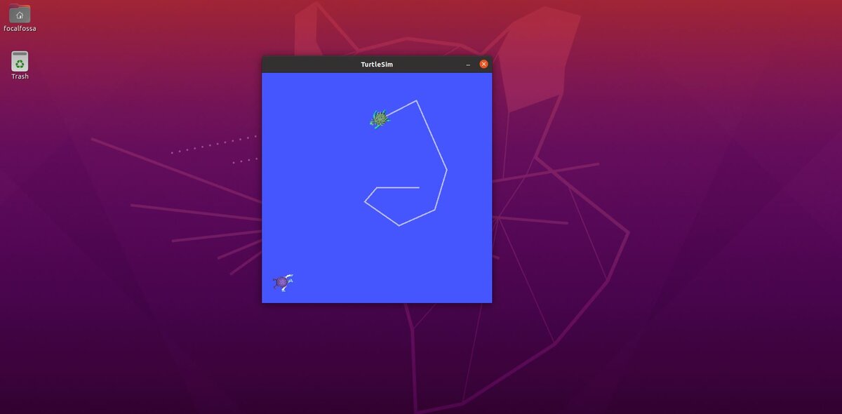
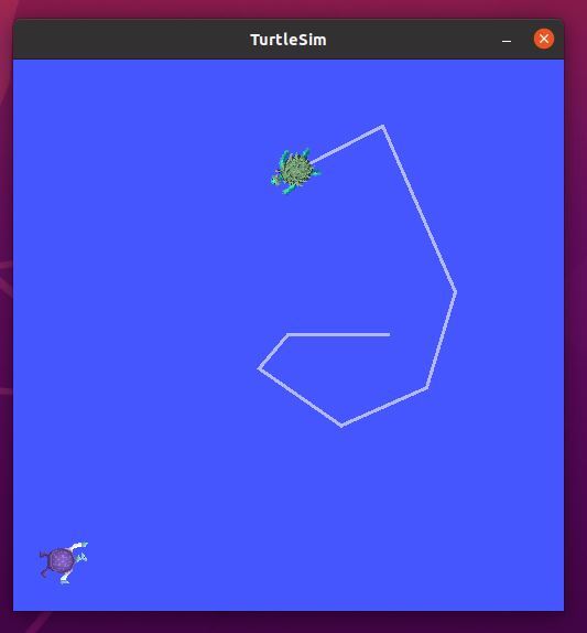
If you go to the terminal and select the terminal where you typed the “ros2 run turtlesim turtle_teleop_key” command, you can move turtle1 around the screen with your keyboard. You will see a green pen color.
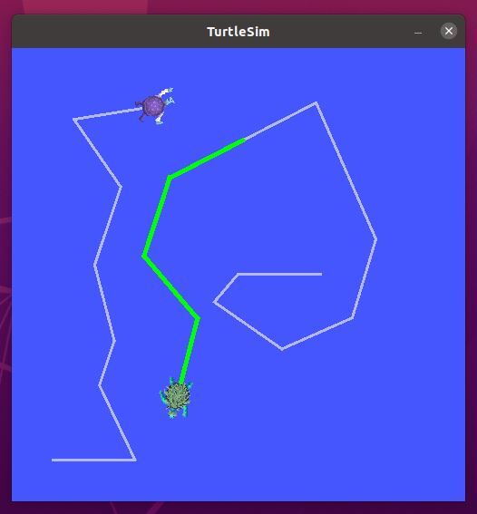
Move turtle2
Let’s move turtle2. To do that, we need to perform remapping. We need to remap the velocity command for turtle1 to turtle2. Open a new terminal tab, and type (this is all a single command):
ros2 run turtlesim turtle_teleop_key --ros-args --remap turtle1/cmd_vel:=turtle2/cmd_vel
You can use your keyboard to move turtle2 around the screen.
To close turtlesim, go to all terminals and type:
CTRL + C