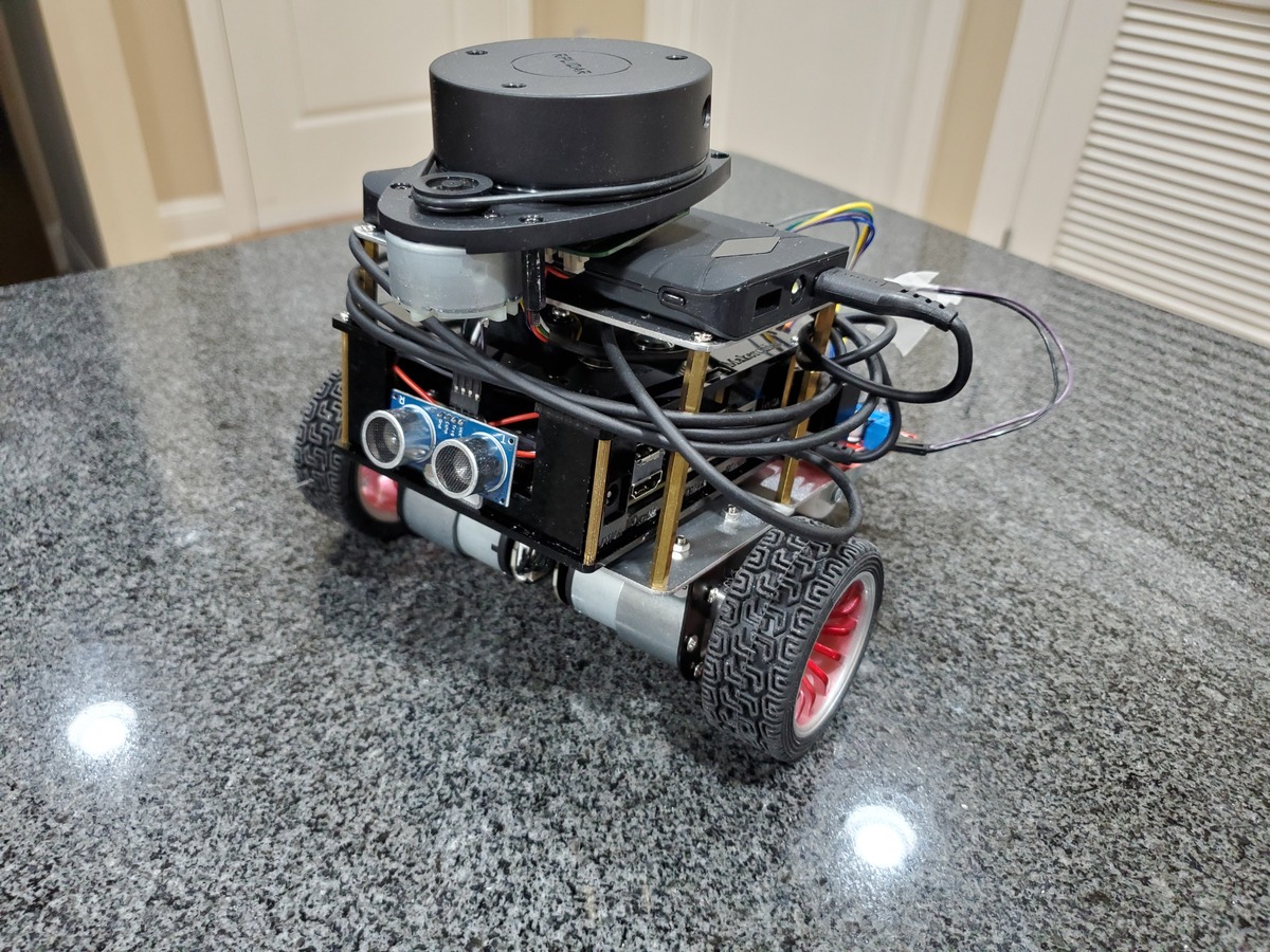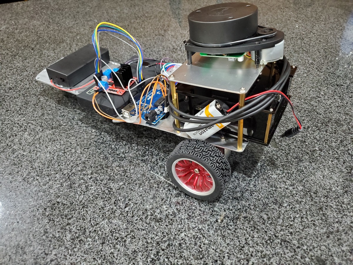
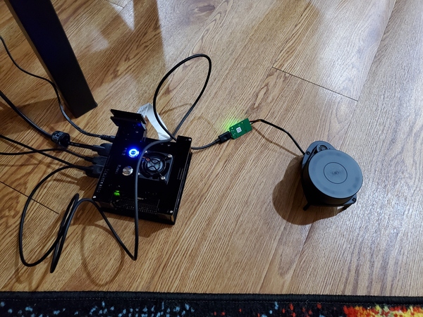
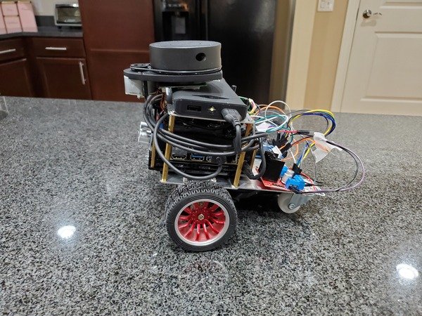
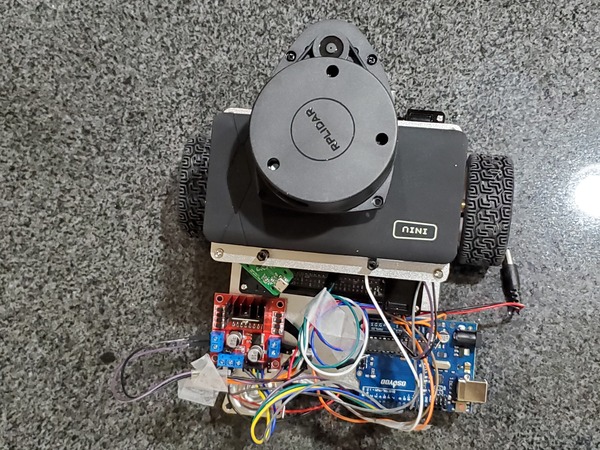
In this tutorial, I will show you how to build a map using LIDAR, ROS 1 (Melodic), Hector SLAM, and NVIDIA Jetson Nano. We will go through the entire process, step-by-step. You can combine what you will learn in this tutorial with an obstacle avoiding robot to build a map of any indoor environment. Below is a small robot I built that wanders around the room while generating a map.
Go through this tutorial slowly so that you set up everything correctly. To go fast, go slow. There is no hurry. Follow along, click-by-click, part-by-part as we develop a complete LIDAR-based SLAM system from scratch.
Real-World Applications
This project has a number of real-world applications:
- Indoor Delivery Robots
- Mapping of Underground Mines, Caves, and Hard-to-Reach Environments
- Robot Vacuums
- Order Fulfillment
- Factories
Prerequisites
- You have already set up your NVIDIA Jetson Nano (4GB, B01) with ROS.
You Will Need
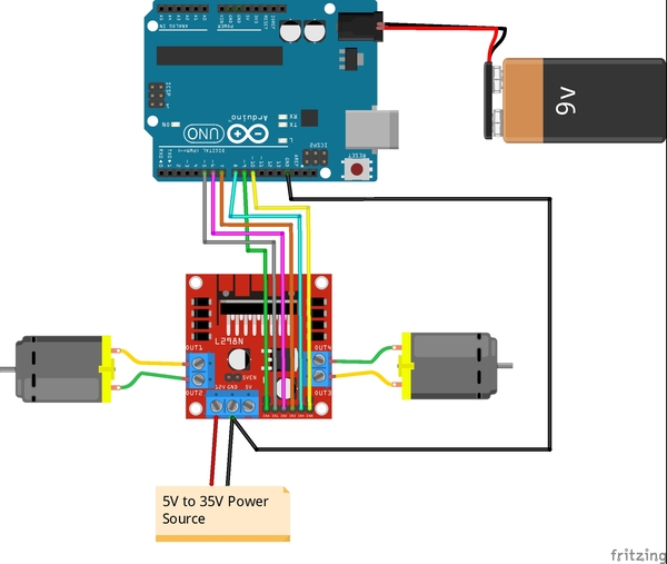
In addition to the parts listed in the article I linked to in the Prerequisites, you will need the following components (#ad).
- INIU Power Bank, LED Display 10000mAh Portable Charger
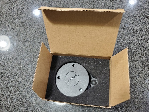
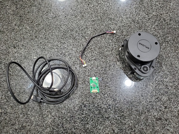
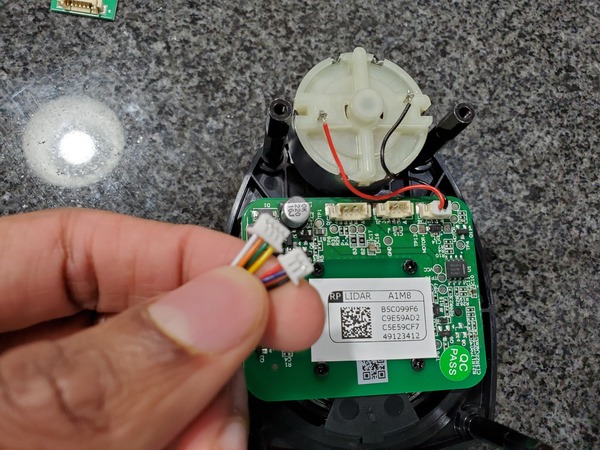
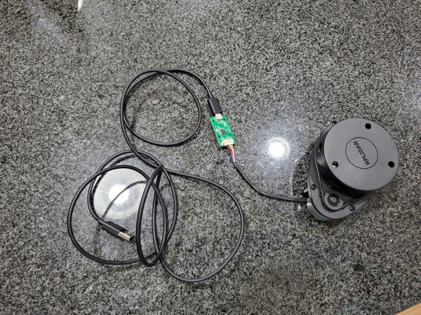
- Slamtec RPLIDAR A1M8 360 Degree 2D Laser Range Lidar Sensor 12 Meters Scanning Radius
- USB to microUSB Cable
- Acrylic Case for Jetson Nano B01 With a Dedicated Cooling Fan (Optional)
Once you finish this project, you can mount your Jetson Nano and LIDAR on anything that moves (drone, robot car, etc.) so you can map an environment.
Disclosure (#ad): As an Amazon Associate I earn from qualifying purchases.
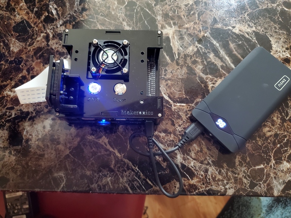
Test the Power Bank
The portable power bank that I purchased can be used to power your Jetson Nano. It outputs 5V/3A. Having a portable power bank enables you to move the Jetson Nano and LIDAR around a room freely so you can build a map.
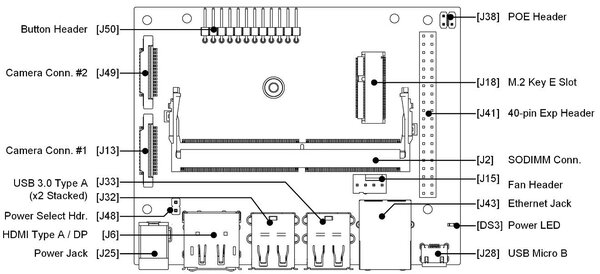
First, take the jumper off of pin J48 so your Jetson Nano knows we are going to plug in the portable battery into the 5V/2A USB Micro B connection (J28) rather than the 5V/4A barrel power jack (J25).
Turn on your Jetson Nano. If your Jetson Nano turns on successfully, the power bank is working.
Shutdown your Jetson Nano.
sudo shutdown -h now
Connect Your RPLIDAR
Connect your RPLIDAR to the Jetson Nano using the USB to microUSB cable.
Turn on your Jetson Nano.
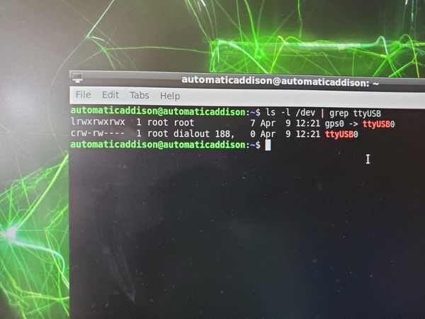
Open a terminal window, and check the permissions. You can copy and paste this command below into the terminal. Note that -l is a lowercase L.
ls -l /dev | grep ttyUSB
Here is the output you should see:
Type this command to change the permissions.
sudo chmod 666 /dev/ttyUSB0
Set Up a Catkin Workspace and Install RPLIDAR ROS Packages
Open a terminal window.
Update the package list.
sudo apt-get update
Install the following dependencies.
sudo apt-get install cmake python-catkin-pkg python-empy python-nose python-setuptools libgtest-dev python-rosinstall python-rosinstall-generator python-wstool build-essential git
Create the catkin workspace.
mkdir -p ~/catkin_ws/src
cd ~/catkin_ws/
So we don’t have to source the setup.bash file every time we open a new Linux terminal, let’s add the ~/catkin_ws/devel/setup.bash command to the .bashrc file. Open a new Linux terminal window.
Type the following command to edit the .bashrc text file:
gedit ~/.bashrc
If you don’t have gedit installed, you can install it using this command.
sudo apt-get install gedit
Make sure these two lines are at the end of the .bashrc file.
source /opt/ros/melodic/setup.bash
source ~/catkin_ws/devel/setup.bash
Save the file, and close it.
Type this command in the current terminal (we won’t need to do this again since we’ve added this command to our bash file).
source ~/catkin_ws/devel/setup.bash
Go to the source folder.
cd src
Clone the RPLIDAR ROS package to your src folder.
sudo git clone https://github.com/Slamtec/rplidar_ros.git
Go to the root of the workspace.
cd ~/catkin_ws/
Compile the workspace.
catkin_make
I saw an error that says “C++11 requires space between literal and string macro.”
The error is occurring in the node.cpp file.
Open that file.
cd ~/catkin_ws/src/rplidar_ros/src
sudo chmod +x node.cpp
sudo gedit node.cpp
We go to line 212.
Change this:
ROS_INFO("RPLIDAR running on ROS package rplidar_ros. SDK Version:"RPLIDAR_SDK_VERSION"");To this:
ROS_INFO("RPLIDAR running on ROS package rplidar_ros. SDK Version:" RPLIDAR_SDK_VERSION "");Go to the root of the workspace.
cd ~/catkin_ws/
Compile the workspace.
catkin_make
Launch the RPLIDAR launch file.
roslaunch rplidar_ros rplidar.launch
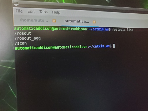
Check out the currently active topics.
Open a new terminal window, and type:
rostopic list
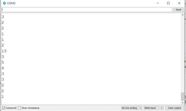
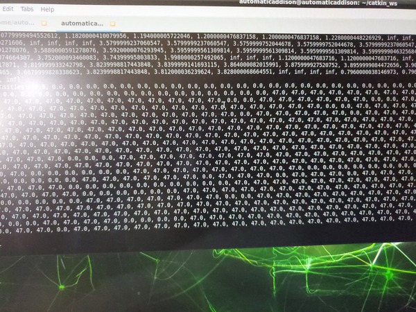
Let’s see what LIDAR data is being published to the /scan ROS topic. Open a new terminal window, and type:
rostopic echo /scan
Here is what you should see.
Keep the terminal window open for the next section.
Run rviz
Now, we will launch rviz, a 3D visualization software program for ROS.
Launch RPLIDAR.
roslaunch rplidar_ros rplidar.launch
Open a new terminal window, and launch rviz.
rviz
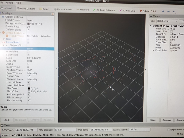
Here is the window that you should see.
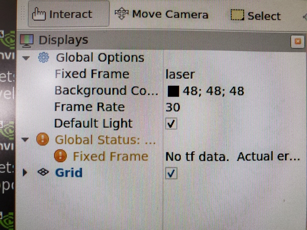
Change the Fixed Frame to laser.
Click the Add button in the bottom-left of the window.
Select LaserScan, and click OK.
Set the LaserScan topic to /scan.
Increase the size to 0.03 so that you can see the data more easily.
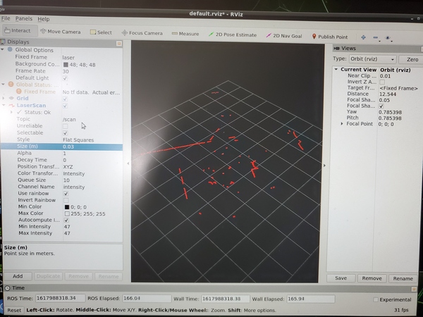
If you see output like this, it means everything is working correctly.
Press CTRL + C in all terminal windows to close everything down.
Build a Map Using the Hector-SLAM ROS Package
In this section, we will build a map of our environment using the ROS Hector-SLAM package.
Hector-SLAM is an algorithm that uses laser scan data to create a map. The advantage of Hector-SLAM over other SLAM techniques is that it only requires laser scan data to do its job. It doesn’t need odometry data.
Hector stands for “Heterogeneous Cooperating Team of Robots”, the name of a robotics research group at TU Darmstadt. The original research paper is available here if you want to learn more about the details (you don’t need to know the details of the algorithm in order to use it in your applications).
SLAM stands for Simultaneous Localization and Mapping. SLAM is a popular technique in which a robot generates a map of an unknown environment (i.e. mapping) while simultaneously keeping track of its position within that map (i.e. localization).
Ok, let’s get started.
Install Qt4
Install Qt4. Qt4 is a software that is used to generate graphical user interfaces.
sudo apt-get install qt4-qmake qt4-dev-tools
Type Y and press Enter to complete the installation. The whole process should take a few minutes.
Download the Hector-SLAM Package
Move to your catkin workspace’s source folder.
cd ~/catkin_ws/src
Clone the Hector-SLAM package into your workspace.
Make sure you have an Internet connection.
ping google.com
If you see streaming data, your Internet is connected properly.
Now download the Hector-SLAM package.
git clone https://github.com/tu-darmstadt-ros-pkg/hector_slam.git
Set the Coordinate Frame Parameters
We need to set the frame names and options correctly.
Go to the launch file for Hector-SLAM. All of this below is a single command, so you can just copy and paste.
sudo gedit ~/catkin_ws/src/hector_slam/hector_mapping/launch/mapping_default.launchSearch for these lines (lines 5 and 6 in my code).
<arg name="base_frame" default="base_footprint"/>
<arg name="odom_frame" default="nav"/>
Change those lines to this:
<arg name="base_frame" default="base_link"/>
<arg name="odom_frame" default="base_link"/>
Now go to the end of this file, and find these lines (line 54 in my code).
<!--<node pkg="tf" type="static_transform_publisher" name="map_nav_broadcaster" args="0 0 0 0 0 0 map nav 100"/>-->Change those lines to this (be sure to remove the comment tags (<!– and –>):
<node pkg="tf" type="static_transform_publisher" name="base_to_laser_broadcaster" args="0 0 0 0 0 0 base_link laser 100"/>Save the file, and return to the terminal window.
Type the following command.
cd ~/catkin_ws/src/hector_slam/hector_slam_launch/launch
Open the tutorial.launch file.
gedit tutorial.launch
Find this line (line 7 in my code).
<param name="/use_sim_time" value="true"/>Change that line to:
<param name="/use_sim_time" value="false"/>Save the file, and close it.
Open a new terminal window, and type this command:
cd ~/catkin_ws/
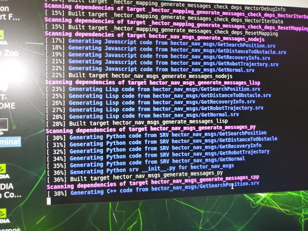
Build the packages.
catkin_make
If you see this error message…
Project ‘cv_bridge’ specifies ‘/usr/include/opencv’ as an include dir, which is not found. It does neither exist as an absolute directory nor in…
Type:
cd /usr/include
sudo ln -s opencv4/ opencv
Build the packages again.
cd ~/catkin_ws/
catkin_make
Wait a minute or two while the Hector-SLAM package builds.
Let’s reboot the computer. I’ll do a complete shutdown then turn the Jetson Nano on again.
sudo shutdown -h now
Launch Mapping
Turn on the Jetson Nano.
Open a new terminal window, and launch RPLIDAR.
cd ~/catkin_ws/
sudo chmod 666 /dev/ttyUSB0
roslaunch rplidar_ros rplidar.launch
Now that the LIDAR is running, let’s start mapping. Open a new terminal, and type the following command:
roslaunch hector_slam_launch tutorial.launch
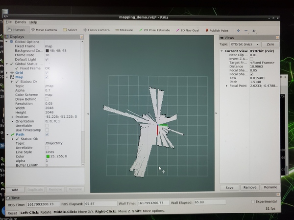
This command above launches three nodes as well as rviz:
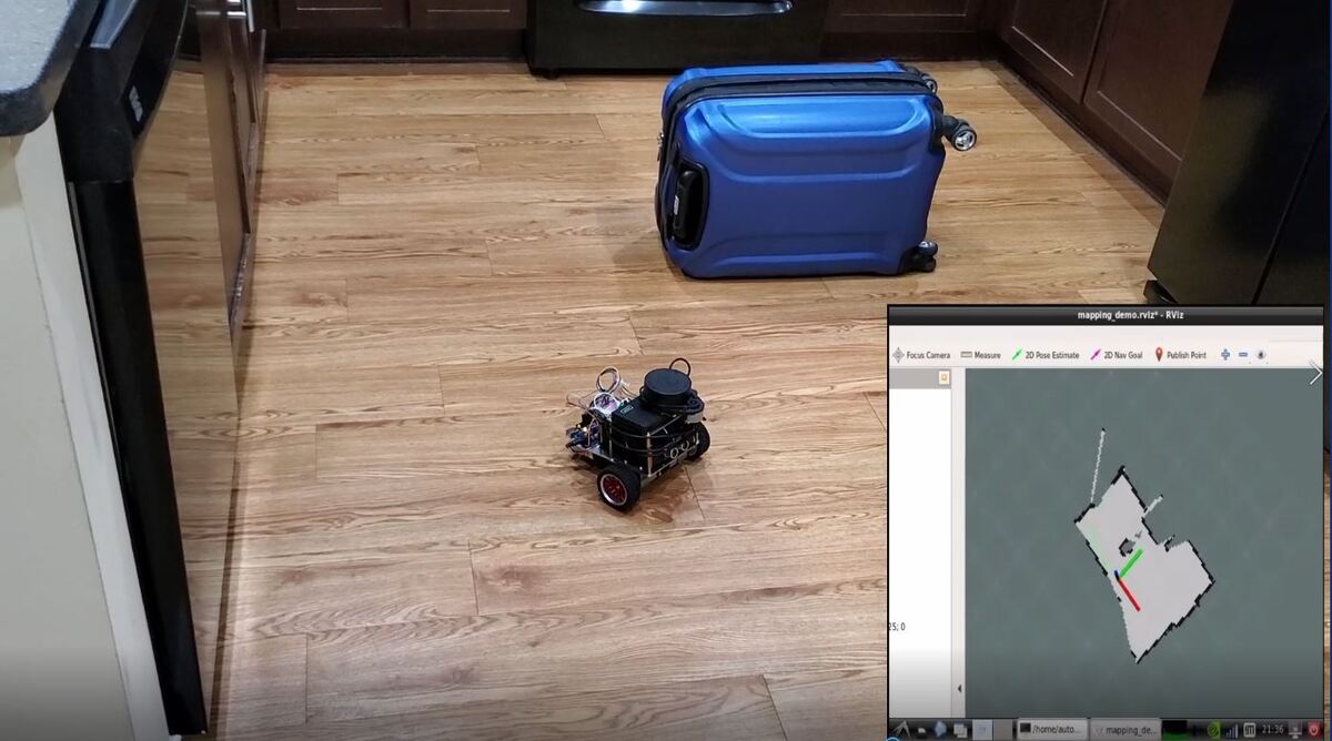
If you move the LIDAR around the room, make sure that it moves very slowly so that you can create a good map. Map-making works best at slow speeds. Here are some photos of the robot I built. It combines obstacle avoidance and LIDAR-based mapping.

Save the Map
Method 1
Let’s save the map. Open a new terminal window, and type:
rostopic pub syscommand std_msgs/String "savegeotiff"
When you’re done running mapping, type CTRL + C on all terminal windows.
Go to ~/catkin_ws/src/hector_slam/hector_geotiff/maps.
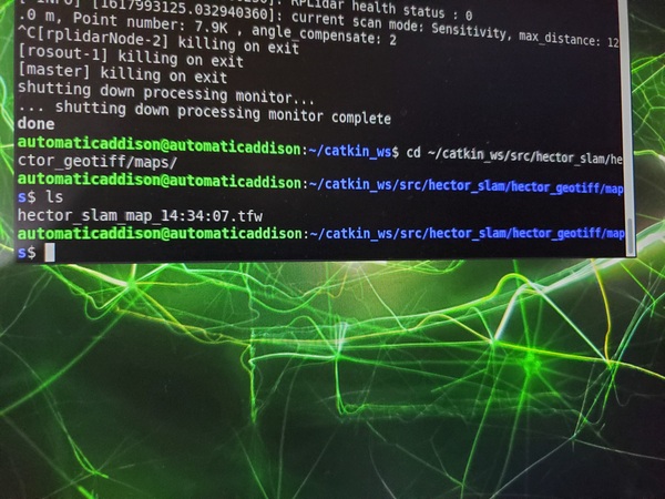
You can find your own map like hector_slam_map_##:##:##.tfw.
Method 2
Another way to save a map is to use a package called map_server. This package will save map data to a yaml and pgm formatted file.
Before you launch the mapping process, you need to install map_server.
sudo apt-get install ros-melodic-map-server
Create a maps folder. This is where we will store our maps.
mkdir ~/catkin_ws/maps
Launch the mapping process (see Launch Mapping section above).
When you are happy with the map that you see in rviz, you can save the map as my_map.yaml and my_map.pgm. Open a new terminal.
cd ~/catkin_ws/maps
rosrun map_server map_saver -f my_map
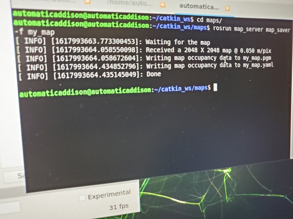
Maps will save to the ~/catkin_ws/maps directory.
Press CTRL + C on all terminal windows to shut everything down.
Load a Saved Map
To view the map, you can run the following command in a new terminal window to get the ROS Master started..
cd ~/catkin_ws/maps
roscore
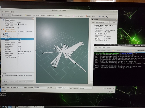
Now load the map. In a new terminal window, type:
rosrun map_server map_server my_map.yaml
Open rviz in another terminal.
rviz
Click Add in the bottom left, and add the Map display.
Under Topic under the Map section, select /map.
You should see the saved map on your screen.
Press CTRL + C to close everything down.
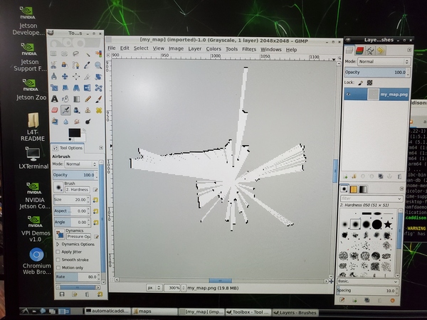
Convert the Map into png Format
To convert the map to a png image file, you can use imagemagick.
sudo apt-get install imagemagick
convert my_map.pgm my_map.png
Edit the Map
To edit the map, I recommend using a program like GIMP.
Install gimp.
sudo apt-get update
sudo apt-get install gimp
Run gimp.
gimp
To load the image, go to File -> Open, and then locate your image.
That’s it. Keep building!
References
This tutorial was especially helpful.