
In the previous tutorial, we built a simulated mobile robot base from scratch. Now I want to create a robotic arm that I will eventually attach to this base so that I have a complete mobile manipulator. Here is what we will build:
This tutorial would not have been possible without Ramkumar Gandhinathan and Lentin Joseph’s awesome book ROS Robotics Projects Second Edition (Disclosure: As an Amazon Associate I earn from qualifying purchases). I highly recommend it if you want to learn ROS 1. Many of the files (URDF, configuration, and STL files), come from their book’s public GitHub page.
Real-World Applications
This project has a number of real-world applications:
- Indoor Delivery Robots
- Order Fulfillment
- Factories
- Warehouses
- Space Exploration
- Power Plants
Let’s get started!
Prerequisites
- You have completed this tutorial where you learned how to create a mobile robot base.
Build the Robot Arm
Open a new terminal window.
Move to the urdf folder of your package.
roscd mobile_manipulator_body/urdf/
Now create a file named robot_arm.urdf.
gedit robot_arm.urdf
Add the robot_arm.urdf code inside there.
Save and close the file.
Test the Robot Arm
Now let’s launch the robot arm.
Open a new terminal window, and go to the package.
roscd mobile_manipulator_body/urdf/
roslaunch urdf_tutorial display.launch model:=robot_arm.urdf
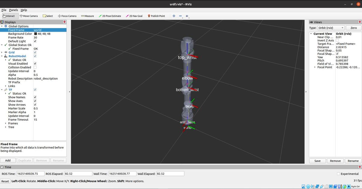
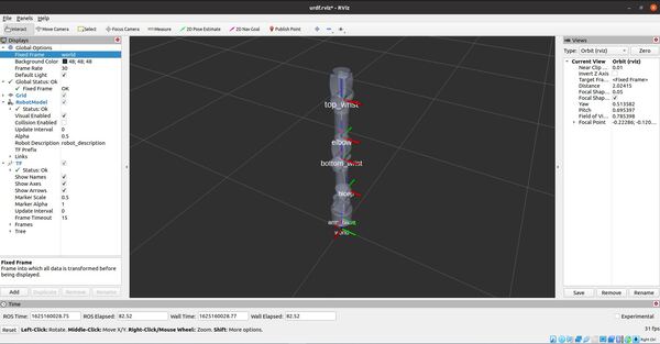
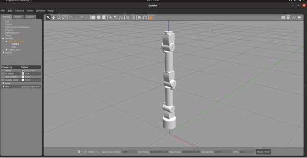
Change the Fixed Frame to world.
Here is how the robot looks.
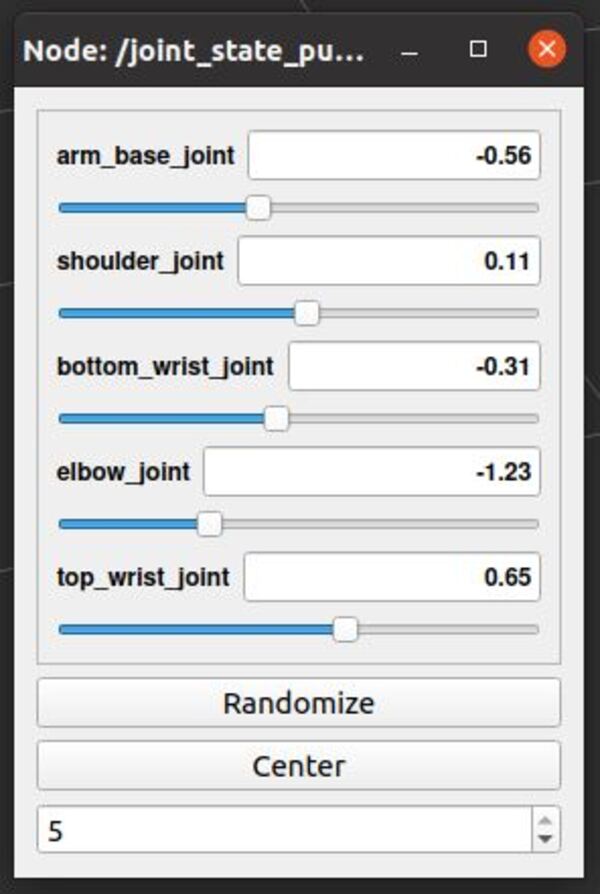
Move the arm using the sliders.
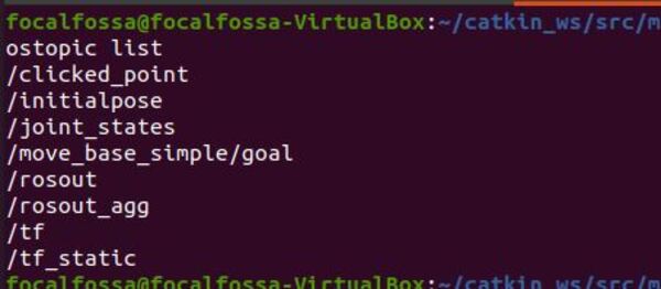
Here are the active ROS topics.
rostopic list
Press CTRL + C in all open terminal windows to close everything down.
Now, let’s set up the configuration parameters for the controllers.
Open a new terminal window.
Go to the config file of your package.
roscd mobile_manipulator_body/config/
Now create a file named arm_control.yaml.
gedit arm_control.yaml
Add the arm_control.yaml code inside there.
Save and close the file.
Now create a file named joint_state_controller.yaml.
gedit joint_state_controller.yaml
Add the joint_state_controller.yaml code inside there.
Save and close the file.
Launch the Robot Arm
Now let’s launch the robot arm.
Open a new terminal window, and go to the package.
roscd mobile_manipulator_body/launch/
Create a new launch file.
gedit arm_gazebo_control.launch
Add the arm_gazebo_control.launch code inside there.
Save and close the file.
Now let’s launch the robot in Gazebo.
Open a new terminal window.
Move to your catkin workspace.
cd ~/catkin_ws/
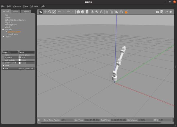
roslaunch mobile_manipulator_body arm_gazebo_control.launch
Here is how the robot arm looks.
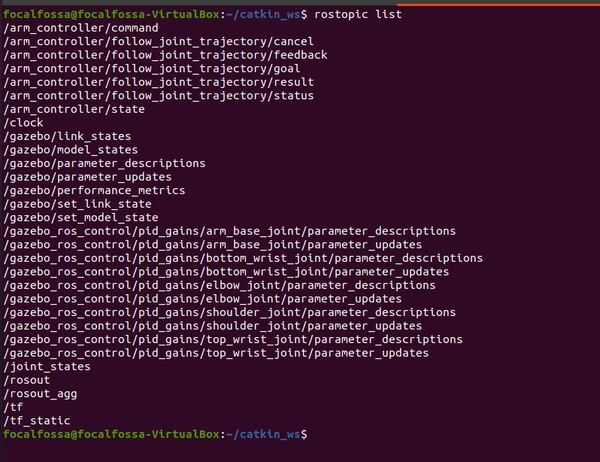
Here are the active ROS topics.
rostopic list
Open a new terminal, and type this command to move the robot arm a little bit:
rostopic pub /arm_controller/command trajectory_msgs/JointTrajectory '{joint_names: ["arm_base_joint","shoulder_joint", "bottom_wrist_joint", "elbow_joint","top_wrist_joint"], points: [{positions: [-0.1, 0.5, 0.02, 0, 0], time_from_start: [1,0]}]}' -1
Type this command to bring the robot back to the home position.
rostopic pub /arm_controller/command trajectory_msgs/JointTrajectory '{joint_names: ["arm_base_joint","shoulder_joint", "bottom_wrist_joint", "elbow_joint","top_wrist_joint"], points: [{positions: [0, 0, 0, 0, 0], time_from_start: [1,0]}]}' -1
References
ROS Robotics Projects Second Edition