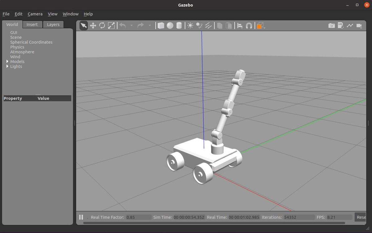
In this tutorial, I will show you how to set up and control a robotic arm using MoveIt and ROS. MoveIt is a motion planning software for robotic arms. Here is the output:
Real-World Applications
This project has a number of real-world applications:
- Indoor and Outdoor Delivery Robots
- Room Service Robots
- Robot Vacuums
- Order Fulfillment
- Manufacturing
- Factories
Our robot will exist in a world that contains a post office and three houses. The use case for this simulated robot would be picking up packages at a post office and delivering them to houses in a neighborhood.
Let’s get started!
Prerequisites
- You have completed this tutorial where you learned how to create a simulated mobile manipulator.
- You have completed this tutorial where you set up and configured the ROS Navigation Stack for your robot.
All the code you need is located at this link.
Install MoveIt
Let’s install MoveIt.
Open a new terminal window, and type the following commands:
sudo apt install ros-noetic-moveit
sudo apt-get install ros-noetic-moveit-setup-assistant
sudo apt-get install ros-noetic-moveit-simple-controller-manager
sudo apt-get install ros-noetic-moveit-fake-controller-manager
Configure the Robotic Arm
Let’s use the MoveIt Setup Assistant to configure our robotic arm.
Open a new terminal window, and type the following command.
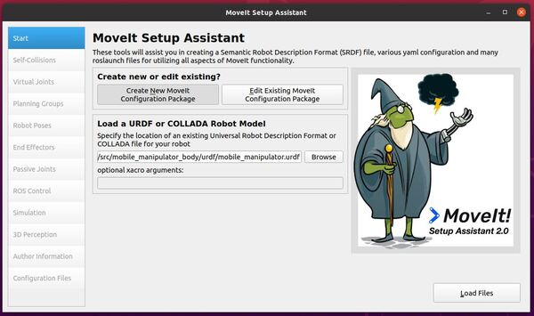
roslaunch moveit_setup_assistant setup_assistant.launch
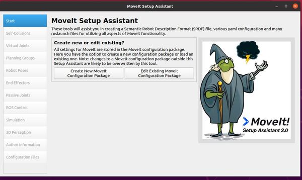
Click Create New MoveIt Configuration Package.
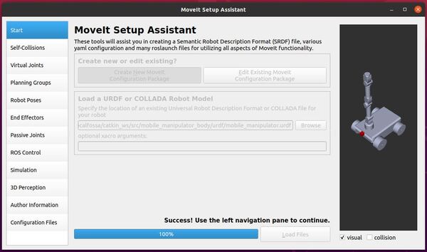
Load the mobile_manipulator.urdf file. Click Load Files.
If the URDF file loads properly, you will see a success message.
Click the Self-Collisions tab on the left-hand side.
Click Generate Collision Matrix.
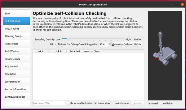
If you wish, you can manually enable pairs of links for which you want MoveIt to check for collisions during the motion planning process. I will leave the defaults as-is.
Let’s skip the Virtual Joints tab. We won’t have any virtual joints for our mobile manipulator.
Click the Planning Groups tab.
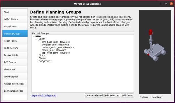
Click Add Group.
Let’s call the group arm.
In the Kinematic Solver dropdown box, select the kdl_kinematics_plugin/KDLKinematicsPlugin.
Keep the resolution and timeout as the default values.
Choose RRTstar as the Group Default Planner.
Add the five joints of the robotic arm.
Click the Robot Poses tab.
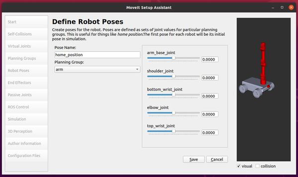
Click Add Pose.
Let’s add a pose for the home position.
Pose Name: home_position
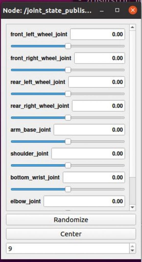
- arm_base_joint: 0.0
- shoulder_joint: 0.0
- bottom_wrist_joint: 0.0
- elbow_joint: 0.0
- top_wrist_joint: 0.0
Click Save.
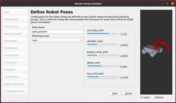
Click Add Pose.
Pose Name: goal_position
- arm_base_joint: 1.5794
- shoulder_joint: -0.9893
- bottom_wrist_joint: -0.9893
- elbow_joint: 0.0
- top_wrist_joint: -0.6769
Click Save.
We don’t have a gripper or suction cup on the end of our robotic arm, so we can skip the End Effectors tab.
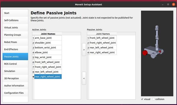
Click the Passive Joints tab. Here is what my setup assistant looks like. I have added all the wheel joints to the passive joints list.
Click the ROS Control tab.
Click the Auto Add FollowJointsTrajectory Controllers For Each Planning Group button.
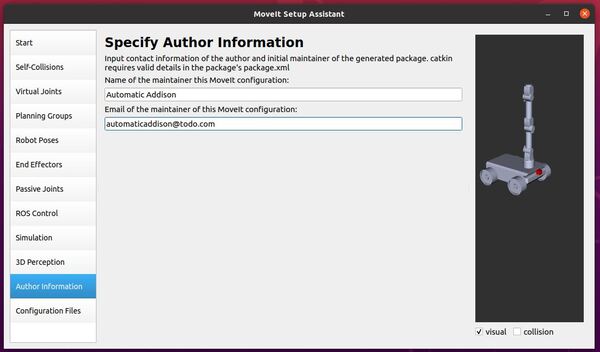
Click the Author Information tab.
Add your name and email address.
Click the Configuration Files tab.
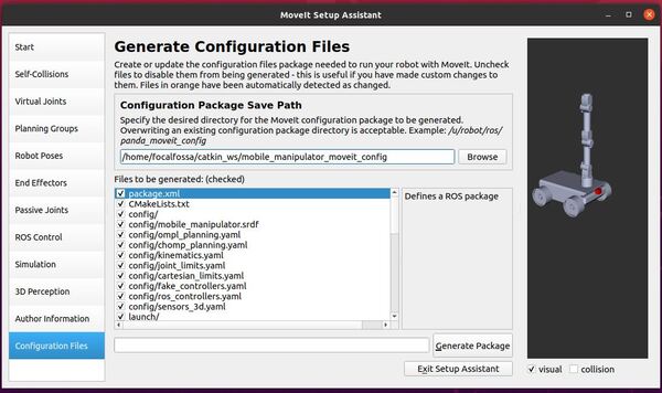
Select the destination where you want to save the configuration files. I will choose my ~catkin_ws/src/ folder. The name of the folder will be mobile_manipulator_moveit_config.
Click Generate Package.
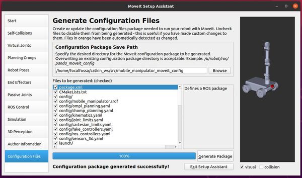
Click Exit Setup Assistant.
Control the Robotic Arm Manually
Let’s install a couple more packages before we get started. Open a terminal window, and type the following commands.
sudo apt-get update
sudo apt install ros-noetic-moveit-resources-prbt-moveit-config
sudo apt install ros-noetic-pilz-industrial-motion-planner
Open your mobile_manipulator_moveit_controller_manager.launch.xml file.
cd ~/catkin_ws/src/mobile_manipulator_moveit_config/launch
gedit mobile_manipulator_moveit_controller_manager.launch.xml
Add this line in the line below the opening <launch> tag:
<arg name="execution_type" default="unused" />
Save the file, and close it.
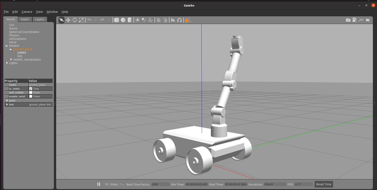
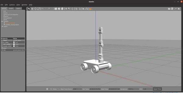
Now, launch the robotic arm in Gazebo by opening a new terminal window, and typing:
roslaunch mobile_manipulator mobile_manipulator_gazebo.launch
Open a new terminal window, and launch MoveIt.
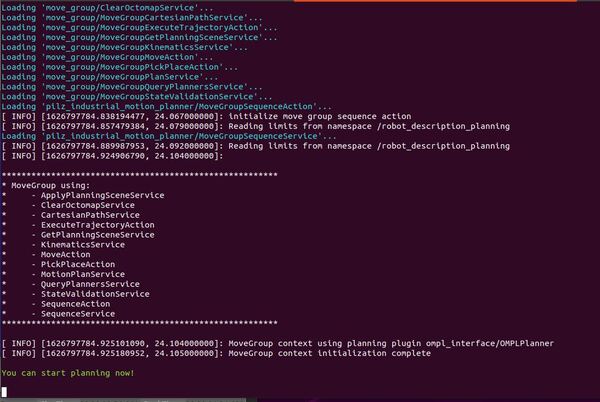
Launch the move_group.launch file by opening a terminal window, and typing:
roslaunch mobile_manipulator_moveit_config move_group.launch
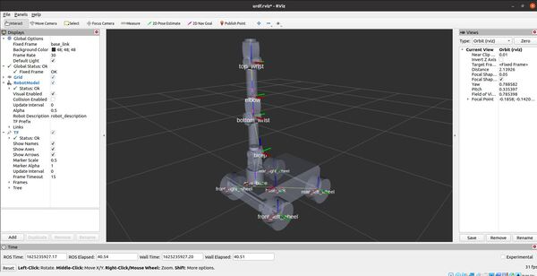
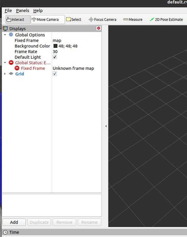
Open another terminal window, and launch RViz. This command below is a single command.
roslaunch mobile_manipulator mobile_manipulator_move_base.launch

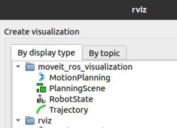
Click Add in the bottom left, and add the Motion Planning plugin under moveit_ros_visualization. If you don’t have the Add button, be sure to go to Panels -> Display on the upper menu to make sure it appears.
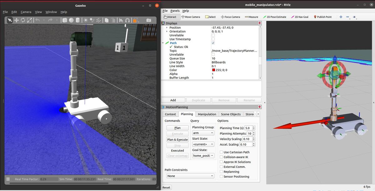
Click the Planning tab.
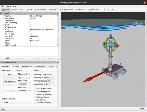
For Goal State, choose goal_position.
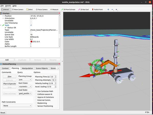
Click Plan & Execute.
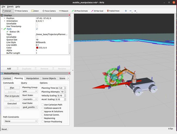
The robotic arm will move to the goal position.
Next Steps
Now you know how to move the robotic arm manually using MoveIt’s RViz interface. If you want to control the robotic arm using code, you can follow this tutorial for C++ or this tutorial for Python.
That’s it! Keep building!