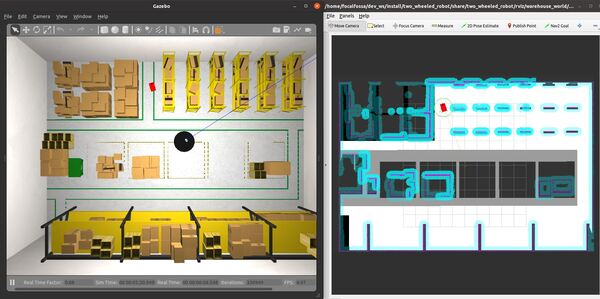
In this tutorial, I will show you how to create an object-following robot using the ROS 2 Navigation Stack (also known as Nav2). The goal is to develop an application that will enable a robot to follow a moving object at a distance indefinitely. Here is the final output you will be able to achieve after going through this tutorial:
The official tutorial is on this page, but we will walk through the steps below.
Developing the code to detect the dynamic object is outside the scope of this tutorial (you can see this post though on how to integrate OpenCV and ROS 2). What we will focus on here is making sure we keep publishing an updated pose (of a dynamic object) to a topic. The Navigation Stack will then have logic to navigate the robot toward that pose.
Real-World Applications
The application that we will develop in this tutorial can be used in a number of real-world robotic applications:
- Person-following robot
- Luggage-carrying robot
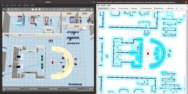
We will focus on creating an application that will follow a moving point (that we set on the map) around a hospital.
Prerequisites
- ROS 2 Foxy Fitzroy installed on Ubuntu Linux 20.04 or newer. I am using ROS 2 Galactic, which is the latest version of ROS 2 as of the date of this post.
- You have already created a ROS 2 workspace. The name of our workspace is “dev_ws”, which stands for “development workspace.”
- You have Python 3.7 or higher.
- (Optional) You have completed my Ultimate Guide to the ROS 2 Navigation Stack.
- (Optional) You have a package named two_wheeled_robot inside your ~/dev_ws/src folder, which I set up in this post. If you have another package, that is fine.
- (Optional) You know how to load a world file into Gazebo using ROS 2.
You can find the files for this post here on my Google Drive.
Create a World
Open a terminal window, and move to your package.
cd ~/dev_ws/src/two_wheeled_robot/worlds
Make sure this world is inside this folder. The name of the file is hospital.world.
Create a Map
Open a terminal window, and move to your package.
cd ~/dev_ws/src/two_wheeled_robot/maps/hospital_world
Make sure the pgm and yaml map files are inside this folder.
My hospital map is made up of two files:
- hospital_world.pgm
- hospital_world.yaml
Create the Parameters File
Let’s create the parameters file.
Open a terminal window, and move to your package.
cd ~/dev_ws/src/two_wheeled_robot/params/hospital_world
Add the nav2_object_following_params.yaml file from this folder.
The definitions of the Behavior-Tree parameters are located on this page.
Create the Behavior Tree XML File
Let’s create the behavior tree.
Open a terminal window, and move to your package.
cd ~/dev_ws/src/two_wheeled_robot/params/hospital_world
Add the follow_point_bt.xml file from this folder. This file comes from here.
Create the RViz Configuration File
Let’s create the RViz configuration file.
Open a terminal window, and move to your package.
cd ~/dev_ws/src/two_wheeled_robot/rviz/hospital_world
Add the nav2_config_object_following.rviz file from this folder.
Create the Launch File
Let’s create the launch file.
Open a terminal window, and move to your package.
cd ~/dev_ws/src/two_wheeled_robot/launch/hospital_world
Add the hospital_world_object_following.launch.py file from this folder.
Launch the Launch File
We will now build our package.
cd ~/dev_ws/
colcon build
Open a new terminal and launch the robot in a Gazebo world.
ros2 launch two_wheeled_robot hospital_world_object_following.launch.py
Command the robot to navigate to any position. Use the Nav2 Goal button at the top of RViz to simulate a new detection of the object of interest.
The robot will follow the point that you click. It will maintain a distance of 1.0 meter behind it.
You can also use this command in the terminal window to set a goal pose. The “object’s location” is published to the /goal_pose topic as a geometry_msgs/PoseStamped type message. All of this stuff below is a single command.
ros2 topic pub -1 /goal_pose geometry_msgs/PoseStamped '{ header: {stamp: {sec: 0, nanosec: 0}, frame_id: "map"}, pose: {position: {x: 5.0, y: 0.0, z: 0.25}, orientation: {w: 1.0}}} '
You can also put the above command in code by creating a publisher node, populating a geometry_msgs/PoseStamped type message inside that node, and publishing that message to the /goal_pose topic.
That’s it! Keep building!
.