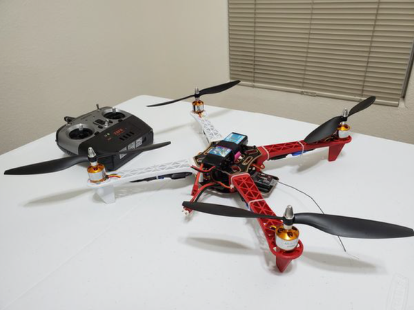
In this post, I’ll show you how to stream GPS data using a Raspberry Pi. To make it more fun, I actually strapped the GPS receiver and Raspberry Pi to a quadcopter and streamed the data via Wifi to my laptop computer. I’ll walk you through all the steps below.
Requirements
Here are the requirements:
- Using a GPS receiver/dongle connected to the Raspberry Pi, capture GPS data, stream via WiFi to my laptop computer and display on my laptop computer.
Prerequisites
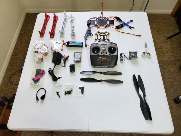
The following components are used in this project. You will need:
Implementation
Hardware
I began by opening a terminal window and typing the following command:
ls /dev/tty*
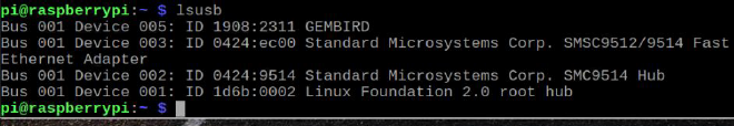
I looked at the devices, then plugged in the GPS unit into the USB port of the Raspberry Pi. I then looked at the terminal again to check for the difference.
Before:
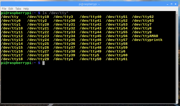
After:
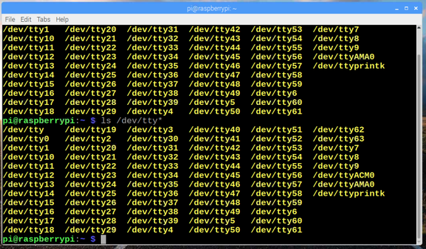
I saw the new entry is /dev/ttyACM0.
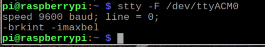
Next, I made sure the tty port is set to a baud rate of 9600.
stty -F /dev/ttyACM0
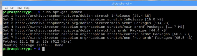
Next, I installed the daemon. The purpose of this step is to install software on the Raspberry Pi that understands the serial data that the GPS module is providing via /dev/ttyAMA0.
sudo aptitude install gpsd gpsd-clients python-gps
I then invoked the daemon using -nN so it doesn’t try to set the baud rate itself.
sudo gpsd -nN /dev/ttyACM0 /var/run/gpsd.sock
I then ran the basic test program to verify gpsd is working.
cgps -s
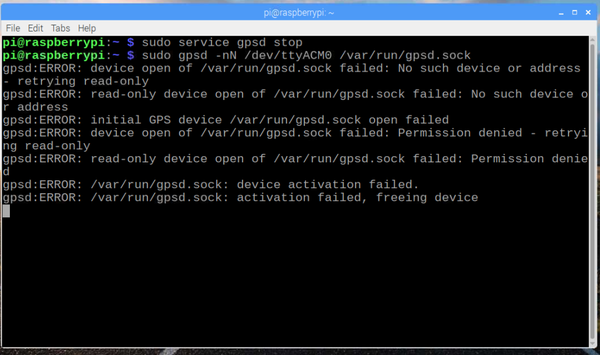
I jump started the service.
sudo service gpsd stop
sudo gpsd -nN /dev/ttyACM0 /var/run/gpsd.sock
I got a lot of error messages.
I then placed the GPS device on the windowsill to have a clear view of the sky.
I opened another terminal window, and typed the following command:
cgps -s
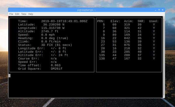
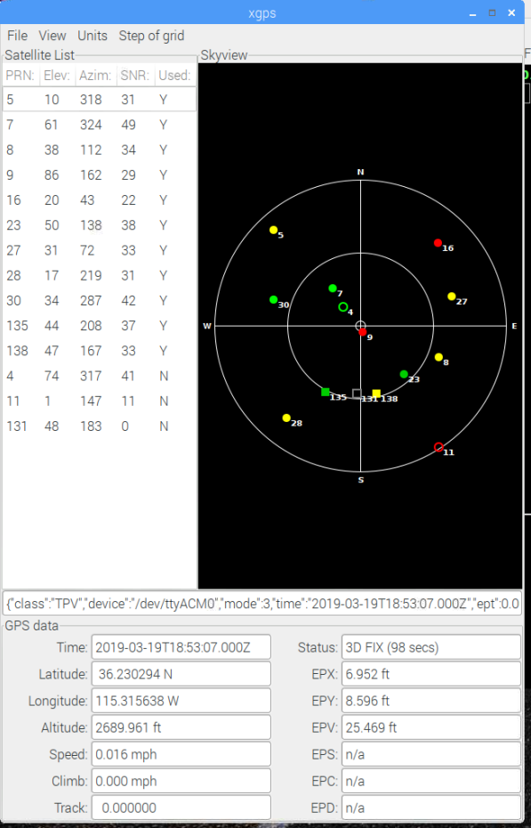
I typed the following command to get a more visual display of the GPS data.
xgps
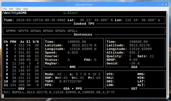
I ran the following command to get a more detailed look at the live-streaming GPS data.
gpsmon
I typed the following command to shutdown the GPS stream:
sudo killall gpsd
To restart the GPS stream I typed
sudo gpsd /dev/ttyAMA0 -F /var/run/gpsd.sock
I then typed the following command to shutdown the GPS stream:
sudo killall gpsd
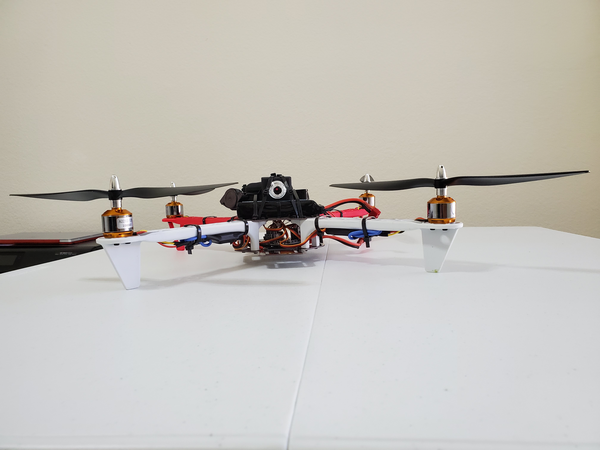
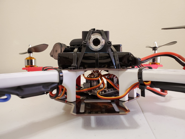
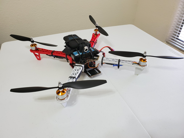
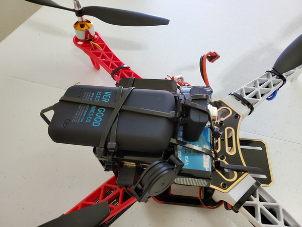
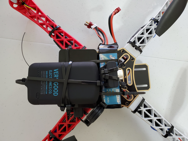
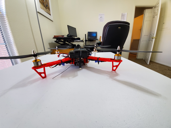
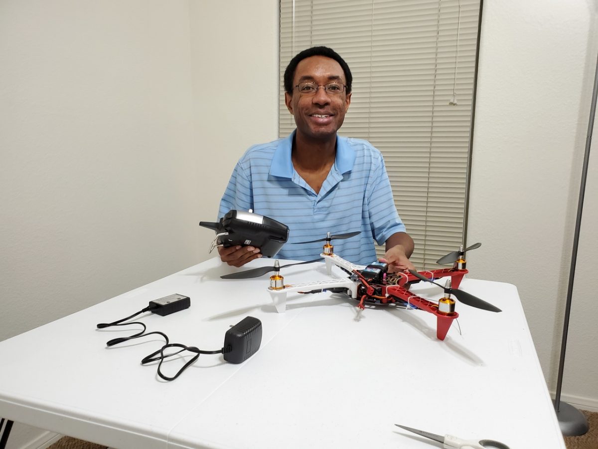
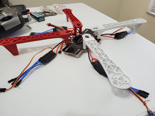
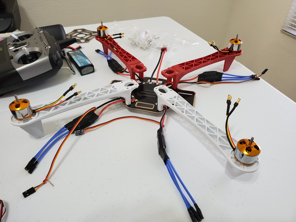
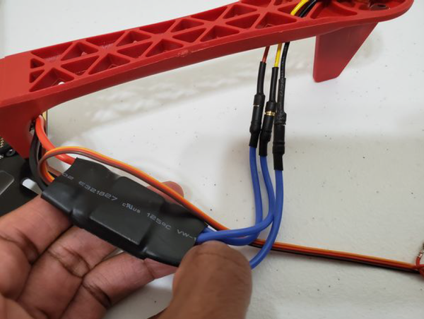
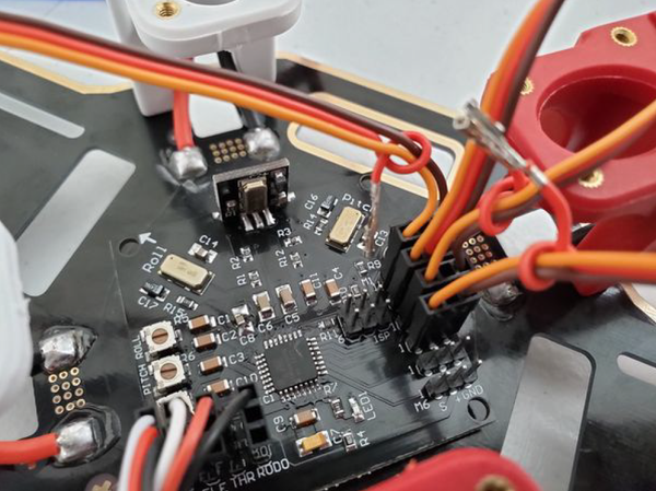
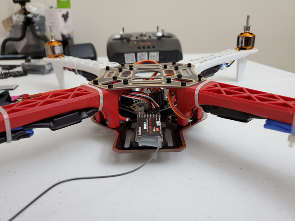
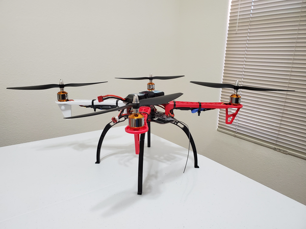
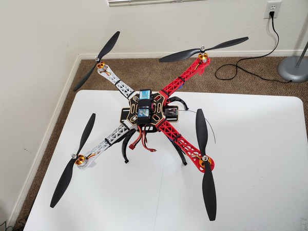
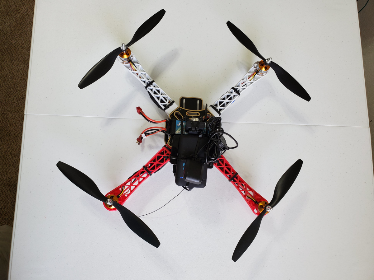
I then mounted the Raspberry Pi and GPS on the quadcopter.
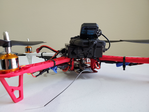
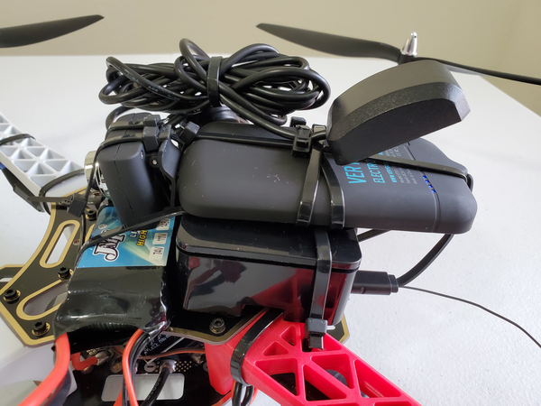
I then flew the quadcopter and streamed the GPS data via WiFi to my host computer.
Software
No extra software was necessary.