How to Send Roll, Pitch, & Yaw Data Over I2C From Arduino to Raspberry Pi

In this post, I’ll show you how to send roll, pitch, and yaw data over I2C using Raspberry Pi and Arduino. We’ll also capture GPS data on the Raspberry Pi to make things interesting for when I mount everything on a quadcopter.

Requirements

Here are the requirements:

  • Using the IMU connected to the Arduino, capture roll, pitch, and yaw data.
  • Using the GPS connected to the Raspberry Pi, capture latitude, longitude, and altitude data.
  • Send the IMU data via I2C to the Raspberry Pi.
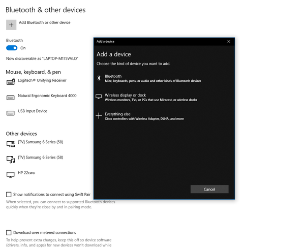
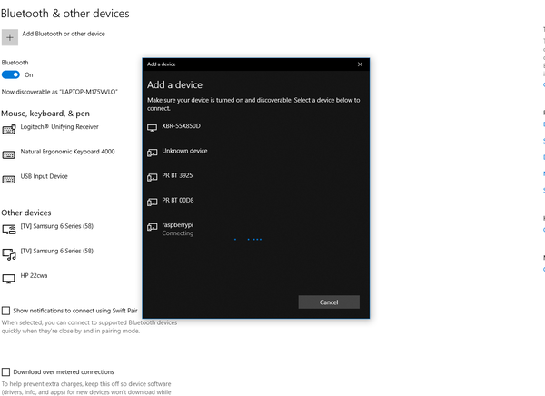
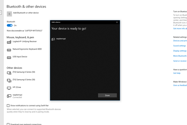
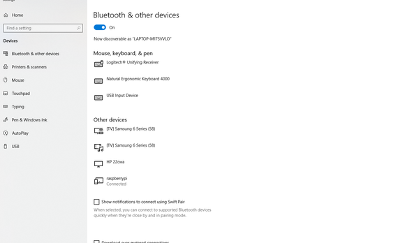
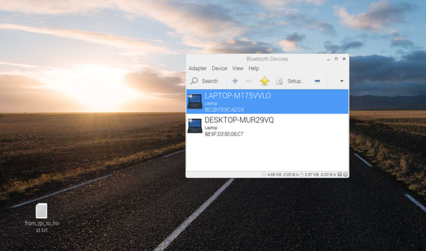
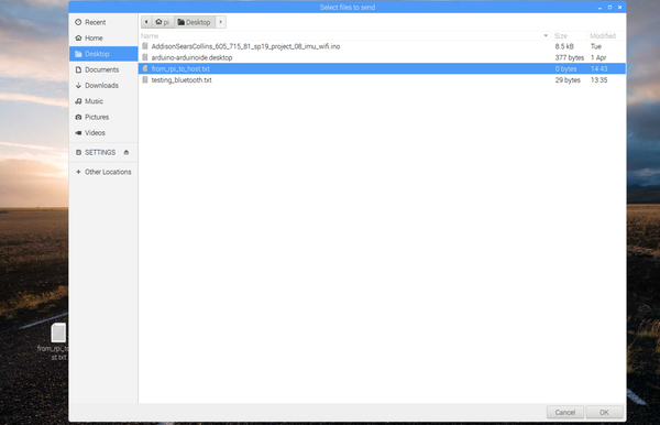
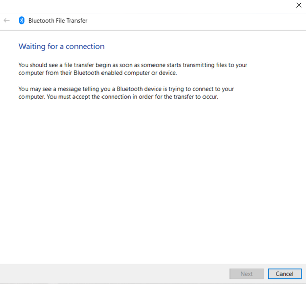
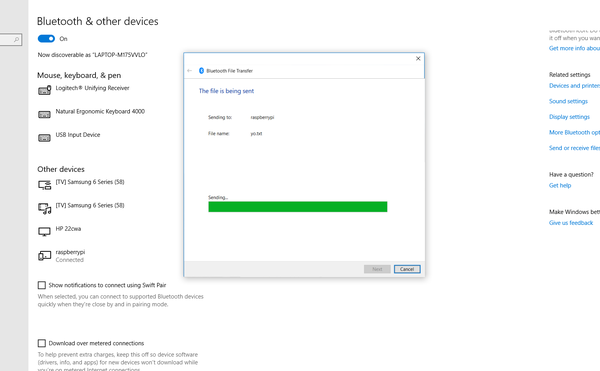
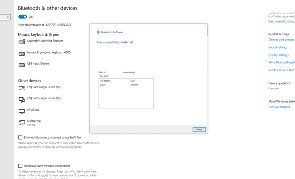
  • Send the IMU and GPS data via Bluetooth from Raspberry Pi to my host computer (e.g. my personal laptop).
  • Display the data on my host computer.
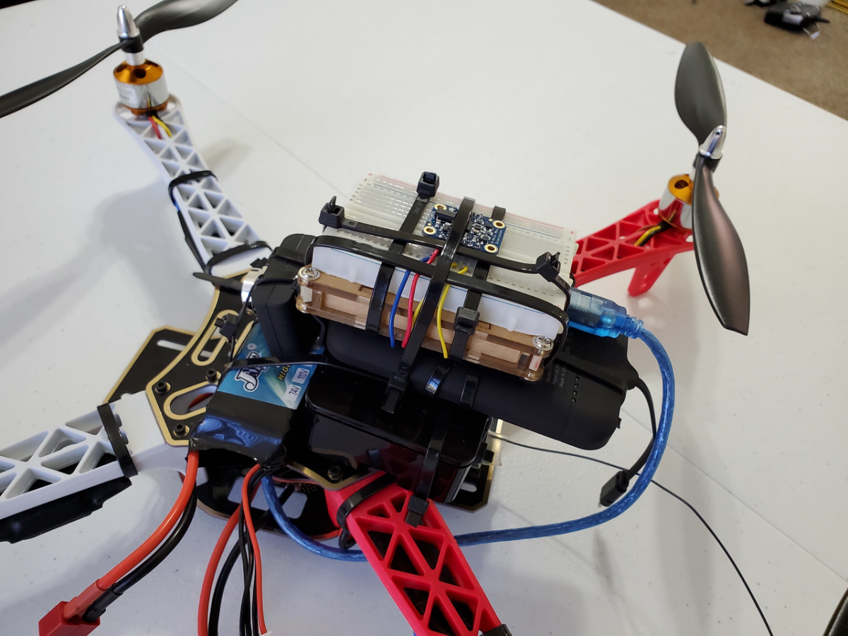
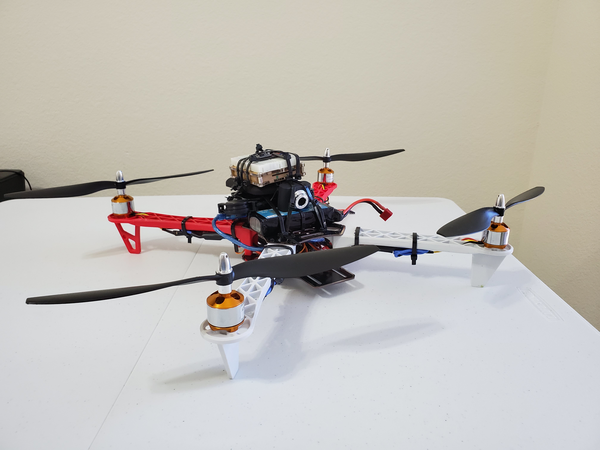
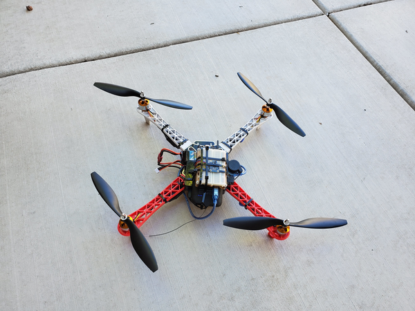
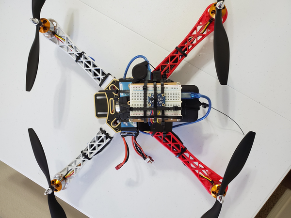
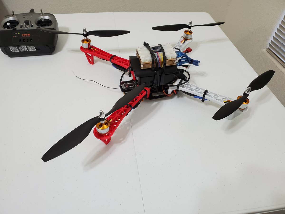
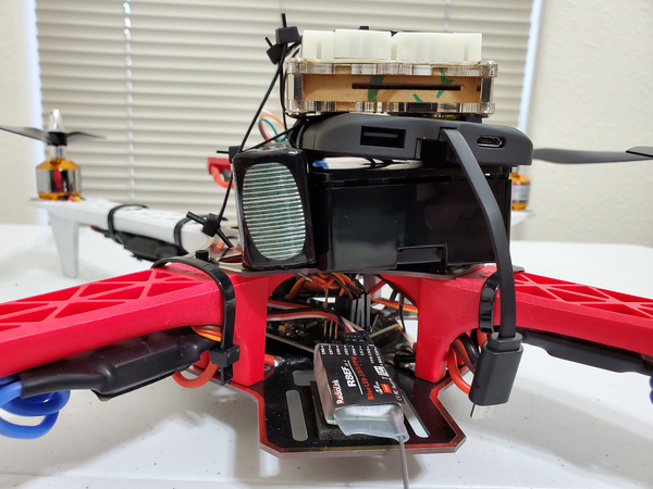
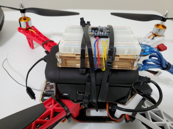
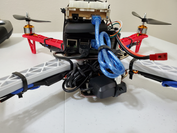
  • To make things interesting, I mounted all the equipment on a quadcopter.

Design

Hardware

The following components are used in this project. You will need:

Software

Here are the steps for the GPS Poller, responsible for capturing Latitude+Longitude+Altitude data on the Raspberry Pi:

  • Open a new file to log the GPS data
  • Create a GPS Poller class
  • Log the latitude data
  • Log the longitude data
  • Log the altitude in feet
  • Delay 5 seconds
  • Close file

Here are the steps for the IMU I2C program on the Arduino, responsible for capturing Roll+Pitch+Yaw data and sending to the Raspberry Pi:

  • Set the delay between fresh samples
  • Define a flag to stop the program
  • Make the Arduino a slave to the Raspberry Pi by defining a slave address
  • Declare a byte array of size 12, which will be the roll+pitch+yaw data (with the sign) to send back to Raspberry Pi
  • Declare variables used for digit extraction
  • Declare function to end the program
  • Display some basic information on the IMU sensor
  • Display some basic info about the sensor status
  • Display sensor calibration status
  • Create method that sends a byte array (of size 12) when reading request is received from the Raspberry Pi
  • Create method that retrieves the digit of any position in an integer. The rightmost digit has position 0. The second rightmost digit has position 1, etc. e.g. Position 3 of integer 245984 is 5.
  • Create Arduino setup function (automatically called at startup) — 9600 Baud Rate
  • Initialize the sensor
  • Set up the Wire library and make Arduino the slave
  • Define the callbacks for i2c communication
  • Need callback that specifies a function when data is received from the RPi Master
  • Need callback that specifies a function when the Master requests data from the Arduino
  • Arduino loop function, called once ‘setup’ is complete
  • While not done:
    • Get a new sensor event
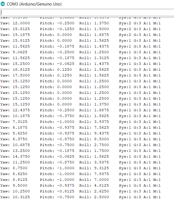
    • Display the floating point data and capture the roll, pitch, and yaw data. Cast the floats to signed integers.
    • Store each digit of the roll, pitch, and yaw data into a byte array (which will be sent to the RPi)
    • End program
  • While true infinite loop

Here are the steps for the I2C Python program on the Raspberry Pi, responsible for sending messages and requesting IMU data via I2C from the Arduino slave:

  • Open a new text file to log the IMU data
  • Set up slave address in the Arduino Program
  • Read a block of 12 bytes starting at SLAVE_ADDRESS, offset 0
  • Extract the IMU reading data
  • Print the IMU data to the console
  • Write the IMU data to the text file
  • Close text file when done
  • Request IMU data every 5 seconds from the Arduino

Implementation

The most straightforward way to connect the Arduino board to the Raspberry Pi is using the USB cable, as I have done in previous projects. However, we can also use I2C. I2C uses two lines: SDA (data) and SCL (clock). It also uses GND (ground).

Here are the connections that I made between the Raspberry Pi and the Arduino:

  • Raspberry Pi SDA (I2C1 SDA) –> Arduino SDA
  • Raspberry Pi SCL (I2C1 SCL) –> Arduino SCL
  • Raspberry Pi GND –> Arduino GND
imu_i2c_1

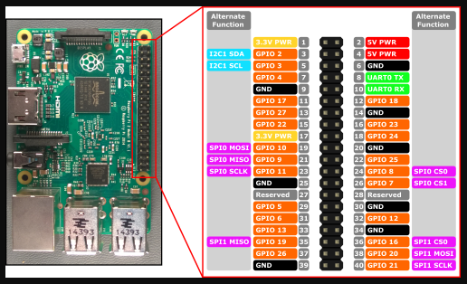
Raspberry Pi 3 Pin Mappings. Image Source: Microsoft.com

imu_i2c_2

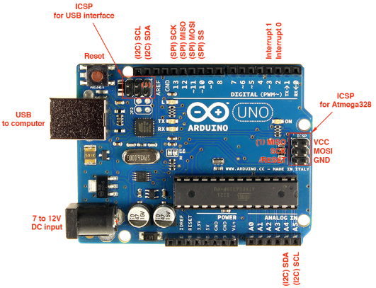
Arduino Uno Pin Mappings. Image Source: Electronics Schematics

Here is the schematic I followed.

imu_i2c_3

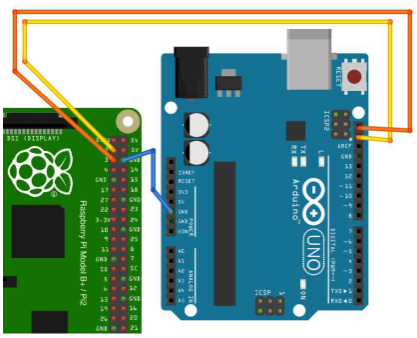
Image Source: Monk (2016)

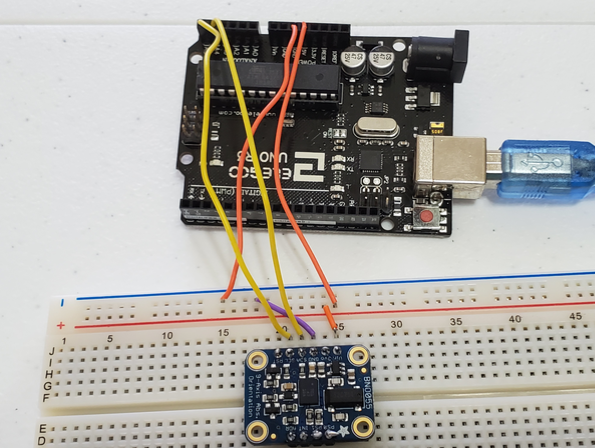
The BNO055 (IMU) was wired to the Arduino Uno using the solderless breadboard as follows:

  • Connected Vin to the power supply of 5V
  • Connected GND to common power/data ground
  • Connected the SDA pin to the I2C data SDA pin on the Arduino (A4).
  • Connected the SCL pin to the I2C clock SCL pin on the Arduino (A5).

To get started with the implementation, I tested the GPS device to see if I can successfully capture GPS latitude + longitude + altitude data on the Raspberry Pi and save it to a text file. This data will later get sent via Bluetooth from Raspberry Pi to my Host computer (HP Omen laptop with Windows 10).

GPS was connected to the Raspberry Pi via the USB cord. The commands for this are as follows:

To start the GPS stream, I typed:

sudo gpsd /dev/ttyAMA0 -F /var/run/gpsd.sock

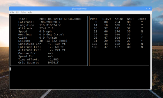
To display the GPS data, I typed the following command:

cgps -s

Here is what the display looked like:

imu_i2c_4

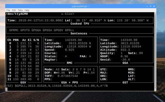
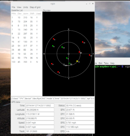
Other commands I could have run are gpsmon and xgps.

gpsmon looks like this:

imu_i2c_5

xgps looks like this:

imu_i2c_6

Sometimes the GPS data did not show up immediately. When that occurred, I rebooted the Raspberry Pi by typing the following command:

sudo reboot

I typed the following command to shutdown the GPS stream:

sudo killall gpsd

Now, I want to do the same thing, but this time I want to save the GPS data to a text file. I will use this syntax in the command terminal in order to save the standard output stream to a text file.

command | tee output.txt

More specifically, I will type:

cgps -s | tee /home/pi/Documents/GPS/output.txt

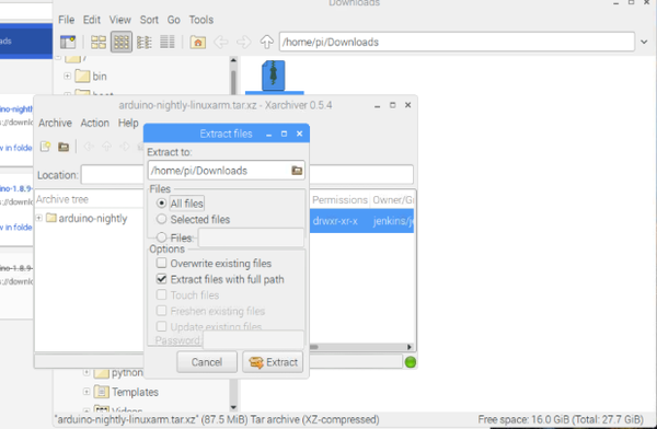
The output.txt was created, and the data was logged in the file. However, it is more useful to output the GPS data in a more user-friendly format. To do this, I will run a Python script that is a GPS polling program. The code for this program is located in the Software section later in this report.

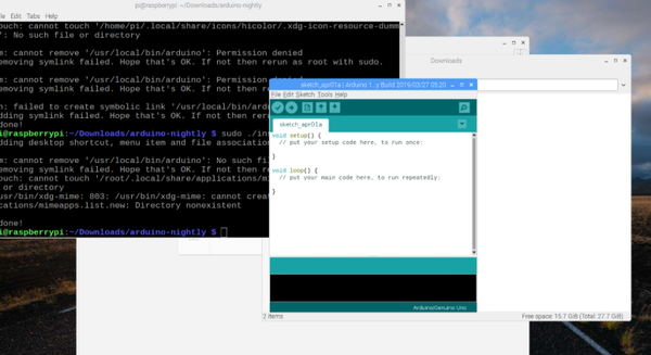
To create the program, I opened the Python IDE (Raspberry Pi -> Programming -> Python 3 (IDLE)).

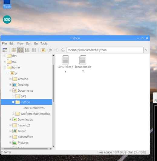
I clicked File -> New File. I then added the code and saved the file as GPSPoller.py.

imu_i2c_7

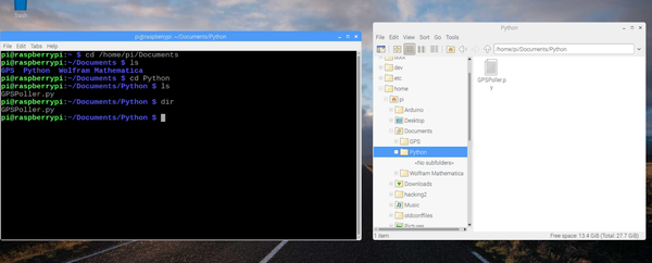
To run the script, I typed

python GPSPoller.py

To stop the script, I pressed Ctrl-C. I could have also pressed Ctrl-Pause/Break.

imu_i2c_8

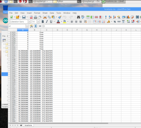
Here is the output of the locations.csv file. For the actual code when I flew the quadcopter, this file was named gps_data.txt.

imu_i2c_9

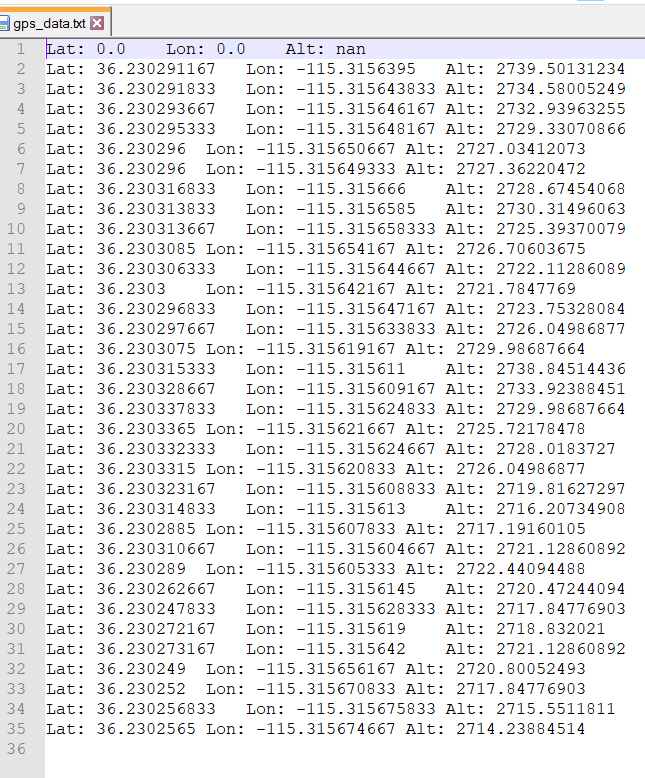
Here is how gps_data.txt looks:

gps_data

Next I connected Arduino to Raspberry Pi via I2C as pictured earlier in this section. I also connected them via USB in order to provide the Arduino with power and to easily upload sketches to the Arduino. BNO055 connects to Arduino.

Next, I followed the instructions inMonk (2016) to make the Arduino the Slave, and the Raspberry Pi the Master. I needed to write code for both the Arduino and the Raspberry Pi in order for them to communicate with each other via I2C (The code for Arduino and Raspberry Pi are in the Software section later in this report).

After writing the Arduino code for I2C communication and IMU data capture, I uploaded the code to the board. I then needed to enable I2C on the Raspberry Pi. I configured Raspberry Pi accordingly by going to Preferences under the main menu, and then clicking Raspberry Pi Configuration -> Interfaces -> Enable I2C.

I now installed the Python I2C library by using the command:

sudo apt-get install python-smbus

It was already installed. I then clicked:

sudo reboot

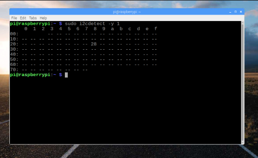
I had my Arduino Uno attached to the Raspberry Pi via I2C. I wanted to check that it’s attached and find its I2C address.

From a Terminal window on my Raspberry Pi, I typed the following commands to fetch and install the i2c-tools:

sudo apt-get install i2c-tools

It was already installed.

Next, I ran the following command:

$ sudo i2cdetect -y 1
imu_i2c_10

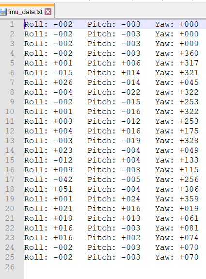
Next, I needed to write the code in Python that the Raspberry Pi can use to make requests for IMU data from the Arduino. That code, as I mentioned above, is in the Software section of this post. I will run this Python script in the terminal window and redirect the IMU data response from the Arduino slave to a text file.

The command to run the Python program is as follows:

sudo python ardu_pi_i2c_imu.py

A file named imu_data.txt will capture the Roll+Pitch+Yaw data. Here is how the data looks:

imu_data

Hardware

imu_i2c_hw 2
imu_i2c_hw 3

Software

Here is the Python script that logs the GPS latitude + longitude + altitude data into a text file on the Raspberry Pi. Don’t be scared at how long the code is. Just copy and paste it into your file:

from gps import *
import time
import threading

# Source: Donat, Wolfram. "Make a Raspberry Pi-controlled Robot :
# Building a Rover with Python, Linux, Motors, and Sensors.
# Sebastopol, CA: Maker Media, 2014. Print.
# Modified by Addison Sears-Collins
# Date April 17, 2019

# Open a new file to log the GPS data
f = open("gps_data.txt", "w")

gpsd = None

# Create a GPS Poller class. 
class GpsPoller(threading.Thread):
  def __init__(self):
    threading.Thread.__init__(self)
    global gpsd
    gpsd = gps(mode=WATCH_ENABLE)
    self.current_value = None
    self.running = True

  def run(self):
    global gpsd
    while gpsp.running:
      gpsd.next()

if __name__ == '__main__':
  gpsp = GpsPoller()
  try:
    gpsp.start()
    while True:
      f.write("Lat: " + str(gpsd.fix.latitude) # Log the latitude data
      + "\tLon: " + str(gpsd.fix.longitude) # Log the longitude data
      + "\tAlt: " + str(gpsd.fix.altitude / .3048) # Log the altitude in feet
      + "\n")
      time.sleep(5)
  except(KeyboardInterrupt, SystemExit):
    f.close()
    gpsp.running = False
    gpsp.join()

Here is the code for the IMU I2C program on the Arduino, responsible for capturing Roll+Pitch+Yaw data and sending to the Raspberry Pi:

#include <Wire.h>
#include <Adafruit_Sensor.h>
#include <Adafruit_BNO055.h>
#include <utility/imumaths.h>

/* This driver uses the Adafruit unified sensor library (Adafruit_Sensor),
   which provides a common 'type' for sensor data and some helper functions.

   To use this driver you will also need to download the Adafruit_Sensor
   library and include it in your libraries folder.

   You should also assign a unique ID to this sensor for use with
   the Adafruit Sensor API so that you can identify this particular
   sensor in any data logs, etc.  To assign a unique ID, simply
   provide an appropriate value in the constructor below (12345
   is used by default in this example).

   Connections
   ===========
   Connect SCL to analog 5
   Connect SDA to analog 4
   Connect VDD to 3-5V DC
   Connect GROUND to common ground

   History
   =======
   2015/MAR/03  - First release (KTOWN)
   2015/AUG/27  - Added calibration and system status helpers

   @Author Modified by Addison Sears-Collins
   @Date   April 17, 2019
*/

/* Set the delay between fresh samples */
#define BNO055_SAMPLERATE_DELAY_MS (100)

Adafruit_BNO055 bno = Adafruit_BNO055(55);

// Flag used to stop the program
bool done = false;

// Make the Arduino a slave to the Raspberry Pi
int SLAVE_ADDRESS = 0X04;

// Toggle in-built LED for verifying program is working
int ledPin = 13;

// Data to send back to Raspberry Pi
byte imu_data[] = {0, 0, 0, 0, 0, 0, 0, 0, 0, 0, 0, 0};

// Variables used for digit extraction
int roll = 0;
int pitch = 0;
int yaw = 0;

// Initialize the LED. This is used for testing.
boolean ledOn = false;

/**************************************************************************/
/*
    This function ends the program
*/
/**************************************************************************/

void end_program() {
    
    // Used for reading data from the serial monitor
    char ch;

    // Check to see if ! is available to be read
    if (Serial.available()) {

    // Read the character
    ch = Serial.read();

    // End the program if exclamation point is entered in the serial monitor
    if (ch == '!') {
      done = true;
      Serial.println("Finished recording Roll+Pitch+Yaw data. Goodbye.");
    }
  } 
}

/**************************************************************************/
/*
    Displays some basic information on this sensor from the unified
    sensor API sensor_t type (see Adafruit_Sensor for more information)
*/
/**************************************************************************/
void displaySensorDetails(void)
{
  sensor_t sensor;
  bno.getSensor(&sensor);
  Serial.println("------------------------------------");
  Serial.print  ("Sensor:       "); Serial.println(sensor.name);
  Serial.print  ("Driver Ver:   "); Serial.println(sensor.version);
  Serial.print  ("Unique ID:    "); Serial.println(sensor.sensor_id);
  Serial.print  ("Max Value:    "); Serial.print(sensor.max_value); Serial.println(" xxx");
  Serial.print  ("Min Value:    "); Serial.print(sensor.min_value); Serial.println(" xxx");
  Serial.print  ("Resolution:   "); Serial.print(sensor.resolution); Serial.println(" xxx");
  Serial.println("------------------------------------");
  Serial.println("");
  delay(500);
}

/**************************************************************************/
/*
    Display some basic info about the sensor status
*/
/**************************************************************************/
void displaySensorStatus(void)
{
  /* Get the system status values (mostly for debugging purposes) */
  uint8_t system_status, self_test_results, system_error;
  system_status = self_test_results = system_error = 0;
  bno.getSystemStatus(&system_status, &self_test_results, &system_error);

  /* Display the results in the Serial Monitor */
  Serial.println("");
  Serial.print("System Status: 0x");
  Serial.println(system_status, HEX);
  Serial.print("Self Test:     0x");
  Serial.println(self_test_results, HEX);
  Serial.print("System Error:  0x");
  Serial.println(system_error, HEX);
  Serial.println("");
  delay(500);
}

/**************************************************************************/
/*
    Display sensor calibration status
*/
/**************************************************************************/
void displayCalStatus(void)
{
  /* Get the four calibration values (0..3) */
  /* Any sensor data reporting 0 should be ignored, */
  /* 3 means 'fully calibrated" */
  uint8_t system, gyro, accel, mag;
  system = gyro = accel = mag = 0;
  bno.getCalibration(&system, &gyro, &accel, &mag);

  /* The data should be ignored until the system calibration is > 0 */
  Serial.print("\t");
  if (!system)
  {
    Serial.print("! ");
  }

  /* Display the individual values */
  Serial.print("Sys:");
  Serial.print(system, DEC);
  Serial.print(" G:");
  Serial.print(gyro, DEC);
  Serial.print(" A:");
  Serial.print(accel, DEC);
  Serial.print(" M:");
  Serial.print(mag, DEC);
}

/**************************************************************************/
/*
    Callback for received data
*/
/**************************************************************************/

void processMessage(int n) {

  char ch = Wire.read();
  if (ch == 'l') {
    toggleLED();
  }
}

/**************************************************************************/
/*
    Method to toggle the LED. This is used for testing.
*/
/**************************************************************************/

void toggleLED() {
  ledOn = ! ledOn;
  digitalWrite(ledPin, ledOn);
  
}

/**************************************************************************/
/*
    Code that executes when request is received from Raspberry Pi
*/
/**************************************************************************/

void sendIMUReading() {
  Wire.write(imu_data, 12); 
}

/**************************************************************************/
/*
    Retrieves the digit of any position in an integer. The rightmost digit
    has position 0. The second rightmost digit has position 1, etc.
    e.g. Position 3 of integer 245984 is 5.
*/
/**************************************************************************/

byte getDigit(int num, int n) {
  int int_digit, temp1, temp2;
  byte byte_digit;

  temp1 = pow(10, n+1);
  int_digit = num % temp1;

  if (n > 0) {
    temp2 = pow(10, n);
    int_digit = int_digit / temp2;
  }

  byte_digit = (byte) int_digit;

  return byte_digit;
}

    
/**************************************************************************/
/*
    Arduino setup function (automatically called at startup)
*/
/**************************************************************************/
void setup(void)
{
  Serial.begin(9600);
  Serial.println("Orientation Sensor Test"); Serial.println("");

  /* Initialise the sensor */
  if(!bno.begin())
  {
    /* There was a problem detecting the BNO055 ... check your connections */
    Serial.print("Ooops, no BNO055 detected ... Check your wiring or I2C ADDR!");
    while(1);
  }

  delay(1000);

  /* Display some basic information on this sensor */
  displaySensorDetails();

  /* Optional: Display current status */
  displaySensorStatus();

  bno.setExtCrystalUse(true);

  pinMode(ledPin, OUTPUT); // This is used for testing.

  Wire.begin(SLAVE_ADDRESS); // Set up the Wire library and make Arduino the slave
  
  /* Define the callbacks for i2c communication */
  Wire.onReceive(processMessage); // Used to specify a function when data received from Master
  Wire.onRequest(sendIMUReading); // Used to specify a function when the Master requests data
  
}

/**************************************************************************/
/*
    Arduino loop function, called once 'setup' is complete
*/
/**************************************************************************/
void loop(void)
{

  while (!done) {
    /* Get a new sensor event */
    sensors_event_t event;
    bno.getEvent(&event);

    /* Display the floating point data */
    Serial.print("Yaw: ");
    yaw = (int) event.orientation.x;
    Serial.print(yaw);
    if (yaw < 0) {
      imu_data[8] = 1;  // Capture the sign information
      yaw = abs(yaw);
    }
    else {
      imu_data[8] = 0;
    }
    if (yaw > 360) {
      yaw = yaw - 360; // Calculate equivalent angle
    } 
    
    Serial.print("\tPitch: ");
    pitch = (int) event.orientation.y;
    Serial.print(pitch);
    if (pitch < 0) {
      imu_data[4] = 1;   // Capture the sign information
      pitch = abs(pitch);
    }
    else {
      imu_data[4] = 0;
    }
    
    Serial.print("\tRoll: ");
    roll = (int) event.orientation.z; 
    Serial.print(roll);
    if (roll < 0) {
      imu_data[0] = 1;    // Capture the sign information
      roll = abs(roll);
    }    
    else {
      imu_data[0] = 0;
    }

    /* Optional: Display calibration status */
    displayCalStatus();

    /* Optional: Display sensor status (debug only) */
    //displaySensorStatus();

    /* New line for the next sample */
    Serial.println("");

    /* Update the IMU data by extracting each digit from the raw data */
    imu_data[1] = getDigit(roll, 2);
    imu_data[2] = getDigit(roll, 1);
    imu_data[3] = getDigit(roll, 0);
    imu_data[5] = getDigit(pitch, 2);
    imu_data[6] = getDigit(pitch, 1);
    imu_data[7] = getDigit(pitch, 0);
    imu_data[9] = getDigit(yaw, 2);
    imu_data[10] = getDigit(yaw, 1);
    imu_data[11] = getDigit(yaw, 0);

    /* Wait the specified delay before requesting nex data */
    delay(BNO055_SAMPLERATE_DELAY_MS);

    end_program();

  }
         
  // Do nothing
  while (true){};

}

Here is the code for the I2C Python program on the Raspberry Pi, responsible for sending messages and requesting IMU data via I2C from the Arduino slave:

import smbus
import time
# Created by Addison Sears-Collins
# April 17, 2019
# Open a new file to log the IMU data
f = open("imu_data.txt", "w")

# for RPI version 1, use bus = smbus.SMBus(0)
bus = smbus.SMBus(1)

# This is the address we setup in the Arduino Program
SLAVE_ADDRESS = 0x04

def request_reading():
  # Read a block of 12 bytes starting at SLAVE_ADDRESS, offset 0
  reading = bus.read_i2c_block_data(SLAVE_ADDRESS, 0, 12)

  # Extract the IMU reading data
  if reading[0] < 1:
    roll_sign = "+"
  else:
    roll_sign = "-"
  roll_1 = reading[1]
  roll_2 = reading[2]
  roll_3 = reading[3]

  if reading[4] < 1:
    pitch_sign = "+"
  else:
    pitch_sign = "-"    
  pitch_1 = reading[5]
  pitch_2 = reading[6]
  pitch_3 = reading[7]

  if reading[8] < 1:
    yaw_sign = "+"
  else:
    yaw_sign = "-" 
  yaw_1 = reading[9]
  yaw_2 = reading[10]
  yaw_3 = reading[11]

  # Print the IMU data to the console
  print("Roll: " + roll_sign + str(roll_1) + str(roll_2) + str(roll_3) +
        "   Pitch: " + pitch_sign + str(pitch_1) + str(pitch_2) + str(pitch_3) +
        "   Yaw: " + yaw_sign + str(yaw_1) + str(yaw_2) + str(yaw_3))

  try:
    f.write("Roll: " + roll_sign + str(roll_1) + str(roll_2) + str(roll_3) +
        "   Pitch: " + pitch_sign + str(pitch_1) + str(pitch_2) + str(pitch_3) +
        "   Yaw: " + yaw_sign + str(yaw_1) + str(yaw_2) + str(yaw_3) + "\n")
  except(KeyboardInterrupt, SystemExit):
    f.close()

# Request IMU data every 5 seconds from the Arduino
while True:
  # Used for testing: command = raw_input("Enter command: l - toggle LED, r - read IMU ")
    # if command == 'l' :
    #   bus.write_byte(SLAVE_ADDRESS, ord('l'))
    # elif command == 'r' :
  request_reading()
  time.sleep(5)

Video

How to Send Roll, Pitch, & Yaw Over Bluetooth | Raspberry Pi and Arduino

In this post, I’ll show you how to send roll, pitch, and yaw data over Bluetooth using Raspberry Pi and Arduino.

Requirements

Here are the requirements:

  • Using the IMU connected to the Arduino, capture roll, pitch, and yaw data.
  • Send the data via Serial over USB to the Raspberry Pi.
  • Send the data via Bluetooth from Raspberry Pi to my host computer (e.g. my personal laptop).
  • Display the data on my host computer.
  • To make things interesting, I mounted the IMU on a quadcopter.

Design

Hardware

The following components are used in this project. You will need:

Software

Here are the steps for the software of the system:

  • Set the delay between fresh samples.
  • Establish a function to end the program when a sentinel is entered (in this case “!”).
  • Define a method that displays some basic information on the sensor.
  • Define a method that displays some basic information about the sensor status.
  • Define a method that displays the sensor calibration status.
  • Setup Function:
    • Initialize serial communication at 9600 bits per second
    • Initialize the sensor.
    • Display some basic information on this sensor.
  • Captures Roll+Pitch+Yaw data from the Adafruit BNO055.
  • Print data to the Serial monitor.
  • Go to new line.
  • Wait a specified delay before requesting the next data.
  • End the program when the sentinel is entered.
  • Infinite loop.

Implementation

My Adafruit BNO055 Absolute Orientation Sensor was already setup from my Wifi roll, pitch, and yaw project. I made some modifications to the software though, which are presented in the Software section.

The BNO055 was wired to the Arduino Uno using the solderless breadboard as follows:

  • Connected Vin to the power supply of 5V
  • Connected GND to common power/data ground
  • Connected the SDA pin to the I2C data SDA pin on the Arduino (A4).
  • Connected the SCL pin to the I2C clock SCL pin on the Arduino (A5).

The challenge in this project is to set up Bluetooth on my Raspberry Pi and send the Roll+Pitch+Yaw data to my host computer.

First, I installed the packages that will enable me to use Bluetooth on my Raspberry Pi.

I opened the Terminal and typed sudo apt-get install bluetooth bluez blueman. I pressed Enter.

1_install_bt_graphical_settings_menu

Here is a description of the packages:

  • Blueman: A full featured Bluetooth manager. It provides a GUI-based setting panel Bluetooth manager.
  • Bluez: Provides the Bluetooth protocol stack and the bluetoothctl utility.
  • Bluetooth: Provides all the plugins supported by Bluez Bluetooth stack.

Once the packages were downloaded and installed, I typed:

sudo reboot

None of that worked, so I tried the steps here to configure the Bluetooth. Bluetooth was back!

I made sure that I turned Bluetooth to on inside my Windows settings.

bluetooth_on
bluetooth_on

I paired with the Raspberry Pi. On the actual Raspberry Pi, I made sure to click “Make Discoverable” under the Bluetooth Manager settings.

3_pairing_correctly_to_external_devicePNG

I went back to my Windows laptop and clicked “Bluetooth” under Add a device.

add_new_device

I added the Raspberry Pi.

make_discoverable
raspberry_pi_paired

The Raspberry Pi and my Windows computer are now paired via Bluetooth.

rpi_connected

To access the Bluetooth graphical settings menu, on the Raspberry Pi desktop, I clicked Menu, located in the upper left corner of the screen, scrolled down to Preferences with the cursor and clicked Bluetooth Manager. From there I clicked “Send Files to Device” to send a test text file via Bluetooth from the Raspberry Pi to the Windows computer.

from_rpi_to_host
from_rpi_to_host

I went to the Bluetooth & other devices settings on my Windows computer and clicked on “Send or receive files via Bluetooth.” I clicked on “Receive files,” which opened up a window. The Windows computer is now ready to receive files.

from_rpi_to_host

I then went back to the Raspberry Pi and selected the test text file and sent it to my Windows computer. I got a prompt on my Windows computer asking where it should be saved. Sending and receiving was successful!

file_sent_successfully

Hardware

I used the same hardware as the Wifi-based roll, pitch, and yaw project.

Software

Here is the code for the program I developed. (Note that after you load the sketch to Arduino, the code runs automatically whenever the Arduino is connected to power. That could be via a battery or power directly from the Raspberry Pi):

#include <Wire.h>
#include <Adafruit_Sensor.h>
#include <Adafruit_BNO055.h>
#include <utility/imumaths.h>

/* This driver uses the Adafruit unified sensor library (Adafruit_Sensor),
   which provides a common 'type' for sensor data and some helper functions.

   To use this driver you will also need to download the Adafruit_Sensor
   library and include it in your libraries folder.

   You should also assign a unique ID to this sensor for use with
   the Adafruit Sensor API so that you can identify this particular
   sensor in any data logs, etc.  To assign a unique ID, simply
   provide an appropriate value in the constructor below (12345
   is used by default in this example).

   Connections
   ===========
   Connect SCL to analog 5
   Connect SDA to analog 4
   Connect VDD to 3-5V DC
   Connect GROUND to common ground

   History
   =======
   2015/MAR/03  - First release (KTOWN)
   2015/AUG/27  - Added calibration and system status helpers
   
   Modified by Addison Sears-Collins on May 3, 2019
*/

/* Set the delay between fresh samples */
#define BNO055_SAMPLERATE_DELAY_MS (100)

Adafruit_BNO055 bno = Adafruit_BNO055(55);

// Flag used to stop the program
bool done = false;

/**
 * This function ends the program.
 */
void end_program() {
    
  // Used for reading data from the serial monitor
  char ch;

  // Check to see if ! is available to be read
  if (Serial.available()) {

    // Read the character
    ch = Serial.read();

    // End the program if exclamation point is entered in the serial monitor
    if (ch == '!') {
      done = true;
      Serial.println("Finished recording Roll+Pitch+Yaw data. Goodbye.");
    }
  } 
}

/**************************************************************************/
/*
    Displays some basic information on this sensor from the unified
    sensor API sensor_t type (see Adafruit_Sensor for more information)
*/
/**************************************************************************/
void displaySensorDetails(void)
{
  sensor_t sensor;
  bno.getSensor(&sensor);
  Serial.println("------------------------------------");
  Serial.print  ("Sensor:       "); Serial.println(sensor.name);
  Serial.print  ("Driver Ver:   "); Serial.println(sensor.version);
  Serial.print  ("Unique ID:    "); Serial.println(sensor.sensor_id);
  Serial.print  ("Max Value:    "); Serial.print(sensor.max_value); Serial.println(" xxx");
  Serial.print  ("Min Value:    "); Serial.print(sensor.min_value); Serial.println(" xxx");
  Serial.print  ("Resolution:   "); Serial.print(sensor.resolution); Serial.println(" xxx");
  Serial.println("------------------------------------");
  Serial.println("");
  delay(500);
}

/**************************************************************************/
/*
    Display some basic info about the sensor status
*/
/**************************************************************************/
void displaySensorStatus(void)
{
  /* Get the system status values (mostly for debugging purposes) */
  uint8_t system_status, self_test_results, system_error;
  system_status = self_test_results = system_error = 0;
  bno.getSystemStatus(&system_status, &self_test_results, &system_error);

  /* Display the results in the Serial Monitor */
  Serial.println("");
  Serial.print("System Status: 0x");
  Serial.println(system_status, HEX);
  Serial.print("Self Test:     0x");
  Serial.println(self_test_results, HEX);
  Serial.print("System Error:  0x");
  Serial.println(system_error, HEX);
  Serial.println("");
  delay(500);
}

/**************************************************************************/
/*
    Display sensor calibration status
*/
/**************************************************************************/
void displayCalStatus(void)
{
  /* Get the four calibration values (0..3) */
  /* Any sensor data reporting 0 should be ignored, */
  /* 3 means 'fully calibrated" */
  uint8_t system, gyro, accel, mag;
  system = gyro = accel = mag = 0;
  bno.getCalibration(&system, &gyro, &accel, &mag);

  /* The data should be ignored until the system calibration is > 0 */
  Serial.print("\t");
  if (!system)
  {
    Serial.print("! ");
  }

  /* Display the individual values */
  Serial.print("Sys:");
  Serial.print(system, DEC);
  Serial.print(" G:");
  Serial.print(gyro, DEC);
  Serial.print(" A:");
  Serial.print(accel, DEC);
  Serial.print(" M:");
  Serial.print(mag, DEC);
}

/**************************************************************************/
/*
    Arduino setup function (automatically called at startup)
*/
/**************************************************************************/
void setup(void)
{
  Serial.begin(9600);
  Serial.println("Orientation Sensor Test"); Serial.println("");

  /* Initialise the sensor */
  if(!bno.begin())
  {
    /* There was a problem detecting the BNO055 ... check your connections */
    Serial.print("Ooops, no BNO055 detected ... Check your wiring or I2C ADDR!");
    while(1);
  }

  delay(1000);

  /* Display some basic information on this sensor */
  displaySensorDetails();

  /* Optional: Display current status */
  displaySensorStatus();

  bno.setExtCrystalUse(true);
}

/**************************************************************************/
/*
    Arduino loop function, called once 'setup' is complete (your own code
    should go here)
*/
/**************************************************************************/
void loop(void)
{

  while (!done) {
    /* Get a new sensor event */
    sensors_event_t event;
    bno.getEvent(&event);

    /* Display the floating point data */
    Serial.print("Yaw: ");
    Serial.print(event.orientation.x, 4);
    Serial.print("\tPitch: ");
    Serial.print(event.orientation.y, 4);
    Serial.print("\tRoll: ");
    Serial.print(event.orientation.z, 4);

    /* Optional: Display calibration status */
    displayCalStatus();

    /* Optional: Display sensor status (debug only) */
    //displaySensorStatus();

    /* New line for the next sample */
    Serial.println("");

    /* Wait the specified delay before requesting next data */
    delay(BNO055_SAMPLERATE_DELAY_MS);

    end_program();

  }
         
  // Do nothing
  while (true){};
}

Video

How to Capture Roll, Pitch, and Yaw Data Using Raspberry Pi and Arduino

In this post, I’ll show you how to capture roll, pitch, and yaw data using Raspberry Pi and Arduino.

Requirements

Here are the requirements:

  • Using the IMU connected to the Arduino, capture roll, pitch, and yaw data.
  • Send the data via Serial over USB to the Raspberry Pi.
  • Send the data via WiFi from Raspberry Pi to my host computer (e.g. my personal laptop).
  • Display the data on my host computer.
  • On the Arduino, use FreeRTOS for tasks.
  • To make things interesting, I mounted the IMU on a quadcopter.

Design

Hardware

The following components are used in this project. You will need:

Software

Here are the steps for the software of the system:

  • Define two tasks for Blink & IMURead. These are function prototypes.
    • The Blink task blinks the built-in LED on the Arduino board.
    • IMURead captures Roll+Pitch+Yaw data from the Adafruit BNO055.
  • Define a method that displays some basic information on the sensor.
  • Define a method that displays some basic information about the sensor status.
  • Define a method that displays the sensor calibration status.
  • Setup Function:
    • Initialize serial communication at 9600 bits per second
    • Wait for serial port to connect (Needed for native USB, on LEONARDO, MICRO, YUN, and other 32u4 based boards).
    • Initialize the sensor.
    • Display some basic information on this sensor.
    • Set up two tasks to run independently.
  • Empty loop since things are done in tasks.

Implementation

I began by testing the Adafruit BNO055 Absolute Orientation Sensor. The BNO055 is three sensors in one device. It includes an accelerometer to measure acceleration forces, a gyroscope that uses Earth’s gravity to help determine orientation, and a magnetometer that measures magnetism. Typical applications of this sensor include navigation, robotics, fitness, augmented reality, and tablet computers.

To setup the BNO055, I first need to prepare the header strip by cutting it to an appropriate length and placing it into the breadboard. I placed the long pins down.

I then added the BNO055 board on top of the pins.

I then soldered all of the pins in order to solidify electrical contact. Here are the steps I took:

  • I put on safety glasses and latex gloves.
  • I turned on the USB fan for ventilation, in order to to breathe in the smoke.
  • I turned on the soldering iron to the 4 heat setting.
  • I placed a damp sponge in the soldering station.
  • Once the iron was hot, I tinned the tip by adding a little bit of solder to cover the tip.
  • I wiped the tip off on the damp sponge to remove all but a thin layer of solder to help the tip last longer and to facilitate the transfer of heat from the soldering iron to the joint.
  • I placed the tip of the soldering iron to the joint to heat it up.
  • I fed a small amount of solder to the joints and removed the soldering iron after 2 seconds in order to not damage the board.
  • With the soldering iron hot, I wiped it off on a damp sponge.
  • I turned off the soldering iron and cleaned everything up.

I wired the BNO055 to the Arduino Uno using the solderless breadboard:

  • Connected Vin to the power supply of 5V
  • Connected GND to common power/data ground
  • Connected the SDA pin to the I2C data SDA pin on the Arduino (A4).
  • Connected the SCL pin to the I2C clock SCL pin on the Arduino (A5).
roll_pitch_yaw_1

Next, I attached the Arduino Uno to the USB port on my computer.

I opened the Library manager and installed the Adafruit_BNO055 driver which supports reading raw sensor data and the Adafruit Unified Sensor system to retrieve orientation data in a standard data format.

I used the Adafruit Sensor System code in order to retrieve the three axis orientation data.

To test the Unified Sensor System output, I opened and ran the sensorapi demo in the Adafruit_BNO055 examples folder.

I also opened and ran the rawdata demo in the Adafruit_BNO055 examples folder.

I opened the Sensor API and redefined the X, Y, and Z variables to Roll, Pitch, Yaw. I assumed that the front of the BNO055 was the part of the sensor labeled BNO055.

I used this website for the assumptions in order to determine which of the variables corresponded to Roll, Pitch, and Yaw. In my analysis, I found that Yaw = X, Pitch = Y, and Roll = Z. I determined this by rotating the BNO055 board around to 90 degrees yaw (East direction), then roll (full roll to the right), and then pitch (BNO055 pointing straight up at the sky), and observing which variable changed to 90 degrees.

I successfully tested the BNO055. It worked properly. Here was the output from the Serial monitor.

roll_pitch_yaw_2

I need to use FreeRTOS for the tasks in the Arduino code for the BNO055.

I opened up Arduino on my desktop computer. I then went to Sketch -> Manage Libraries and looked for FreeRTOS, and installed it.

roll_pitch_yaw_3

Then, I went under the Sketch->Include Library menu to ensure that the FreeRTOS library is included in my sketch.

roll_pitch_yaw_4

I then compiled and upload this empty sketch to my Arduino Uno.

FreeRTOS was now running on my device.

Then I uploaded and tested the example Blink sketch. It is under File -> Examples -> 01.Basics. I inserted #include <Arduino_FreeRTOS.h> at the start of the sketch. I then compiled it and uploaded it to the Arduino Uno.

Then I uploaded and tested the example Blink_AnalogRead.ino sketch. It is under File -> Examples -> FreeRTOS. I made sure #include <Arduino_FreeRTOS.h> was inserted at the start of the sketch. I then compiled it and uploaded it to the Arduino Uno. This sketch combines two basic Arduino examples, Blink and AnalogRead into one sketch with two separate tasks. Both tasks perform their duties independently, managed by the FreeRTOS scheduler.

Next, I downloaded Arduino to my Raspberry Pi. It took me a while to do this since a lot of the blogs and YouTube videos had incorrect instructions. I’ll walk you through everything I did below.

I first followed these steps. This process will enable me to execute the Arduino-Raspberry Pi serial communication.

roll_pitch_yaw_5

I right clicked on the extracted folder and click on open in terminal.

I then typed the below command in the terminal to install the Arduino IDE.

sudo ./install.sh

An error message showed up, which was ignored. The Arduino IDE was supposedly installed.

roll_pitch_yaw_6

I then typed the following command to open up the Arduino IDE

sudo ./arduino

Nothing opened up. This installation attempt failed.

So now, I tried an alternative way of installing Arduino. I typed the following commands as recommended here.

sudo apt-get update && sudo apt-get upgrade
sudo apt-get install arduino

I then restarted the Raspberry Pi.

Still the Arduino IDE would not start. Maybe third time’s a charm.

I then went to the Arduino website and went under “Hourly Builds”. I clicked on “Linux ARM.” I followed these instructions:

I then went to the /home/pi/Downloads folder.

I right clicked on the tar.xz folder and I clicked “Archiver.” I then selected “All Files” and clicked “Extract.”

roll_pitch_yaw_7

I typed the following commands in the terminal window.

cd Downloads
ls
cd arduino-nightly
ls
./install.sh
sudo ./install.sh

I then went to Raspberry Pi in the upper left corner of the screen. Programming -> Arduino IDE.

The Arduino IDE successfully loaded!

roll_pitch_yaw_8

With the Arduino plugged in to the Raspberry Pi USB port, I tried the example Blink sketch under File -> Examples -> 01.Basics in the Arduino IDE. The LED on the Arduino began to blink.

I then opened the Library manager and installed the Adafruit_BNO055 driver which supports reading raw sensor data and the Adafruit Unified Sensor system to retrieve orientation data in a standard data format.

I then went to Sketch -> Manage Libraries and looked for FreeRTOS, and installed it.

To test the Unified Sensor System output, I opened and ran the sensorapi demo in the Adafruit_BNO055 examples folder.

I opened the sensorapi example sketch and redefined the X, Y, and Z variables to Roll, Pitch, Yaw. I assumed that the front of the BNO055 was the part of the sensor labeled BNO055.

I then modified the sensorapi sketch in the Arduino IDE in order to incorporate FreeRTOS.

I also created two tasks so that I could use FREERTOS and get experience with an RTOS.

  • The Blink task blinks the built-in LED on the Arduino board.
  • IMURead captures Roll+Pitch+Yaw data from the Adafruit BNO055.

Hardware

roll_pitch_yaw_9
roll_pitch_yaw_10
roll_pitch_yaw_11
roll_pitch_yaw_12

Software

Here is the code for the program I developed. (Note that after you load the sketch to Arduino, the code runs automatically whenever the Arduino is connected to power. That could be via a battery or power directly from the Raspberry Pi):

#include <Arduino_FreeRTOS.h>
#include <Wire.h>
#include <Adafruit_Sensor.h>
#include <Adafruit_BNO055.h>
#include <utility/imumaths.h>

/* This driver uses the Adafruit unified sensor library (Adafruit_Sensor),
   which provides a common 'type' for sensor data and some helper functions.

   To use this driver you will also need to download the Adafruit_Sensor
   library and include it in your libraries folder.

   You should also assign a unique ID to this sensor for use with
   the Adafruit Sensor API so that you can identify this particular
   sensor in any data logs, etc.  To assign a unique ID, simply
   provide an appropriate value in the constructor below (12345
   is used by default in this example).

   Connections
   ===========
   Connect SCL to analog 5
   Connect SDA to analog 4
   Connect VDD to 3-5V DC
   Connect GROUND to common ground

   History
   =======
   2015/MAR/03  - First release (KTOWN)
   2015/AUG/27  - Added calibration and system status helpers


   In this program, we use the Adafruit BNO055 connected to the Arduino to capture
   Roll+Pitch+Yaw data.

   @author Addison Sears-Collins
   @version 1.0 2019-04-02
*/

Adafruit_BNO055 bno = Adafruit_BNO055(55);

// Define two tasks for Blink & IMURead. These are function prototypes.
// The Blink task blinks the built-in LED on the Arduino board.
// IMURead captures Roll+Pitch+Yaw data from the Adafruit BNO055.
void TaskBlink( void *pvParameters );
void TaskIMURead( void *pvParameters );


/*--------------------------------------------------*/
/*---------------------- Tasks ---------------------*/
/*--------------------------------------------------*/

void TaskBlink(void *pvParameters)  // This is a task.
{
  (void) pvParameters;

/*
  Blink
  Turns on an LED on for one second, then off for one second, repeatedly.

  Most Arduinos have an on-board LED you can control. On the UNO, LEONARDO, MEGA, and ZERO 
  it is attached to digital pin 13, on MKR1000 on pin 6. LED_BUILTIN takes care 
  of use the correct LED pin whatever is the board used.
  
  The MICRO does not have a LED_BUILTIN available. For the MICRO board please substitute
  the LED_BUILTIN definition with either LED_BUILTIN_RX or LED_BUILTIN_TX.
  e.g. pinMode(LED_BUILTIN_RX, OUTPUT); etc.
  
  If you want to know what pin the on-board LED is connected to on your Arduino model, check
  the Technical Specs of your board  at https://www.arduino.cc/en/Main/Products
  
  This example code is in the public domain.

  modified 8 May 2014
  by Scott Fitzgerald
  
  modified 2 Sep 2016
  by Arturo Guadalupi
*/

  // initialize digital LED_BUILTIN on pin 13 as an output.
  pinMode(LED_BUILTIN, OUTPUT);

  for (;;) // A Task shall never return or exit.
  {
    digitalWrite(LED_BUILTIN, HIGH);   // turn the LED on (HIGH is the voltage level)
    vTaskDelay( 1000 / portTICK_PERIOD_MS ); // wait for one second
    digitalWrite(LED_BUILTIN, LOW);    // turn the LED off by making the voltage LOW
    vTaskDelay( 1000 / portTICK_PERIOD_MS ); // wait for one second
  }
}

void TaskIMURead(void *pvParameters)  // This is a task.
{
  (void) pvParameters;
  
/*
  IMUReadSerial
  Capture the Roll+Pitch+Yaw data

*/

  for (;;)
  {
    // Get a new sensor event
    sensors_event_t event;
    bno.getEvent(&event);
   
    /* Display the floating point data */
    Serial.print("Yaw: ");
    Serial.print(event.orientation.x, 4);
    Serial.print("\tPitch: ");
    Serial.print(event.orientation.y, 4);
    Serial.print("\tRoll: ");
    Serial.print(event.orientation.z, 4);

    /* Optional: Display calibration status */
    displayCalStatus();

    /* Optional: Display sensor status (debug only) */
    //displaySensorStatus();

    /* New line for the next sample */
    Serial.println("");
    
    vTaskDelay(7);  // seven tick delay (105ms) in between reads for stability
  }
}

/**************************************************************************/
/*
    Displays some basic information on this sensor from the unified
    sensor API sensor_t type (see Adafruit_Sensor for more information)
*/
/**************************************************************************/
void displaySensorDetails(void)
{
  sensor_t sensor;
  bno.getSensor(&sensor);
  Serial.println("------------------------------------");
  Serial.print  ("Sensor:       "); Serial.println(sensor.name);
  Serial.print  ("Driver Ver:   "); Serial.println(sensor.version);
  Serial.print  ("Unique ID:    "); Serial.println(sensor.sensor_id);
  Serial.print  ("Max Value:    "); Serial.print(sensor.max_value); Serial.println(" xxx");
  Serial.print  ("Min Value:    "); Serial.print(sensor.min_value); Serial.println(" xxx");
  Serial.print  ("Resolution:   "); Serial.print(sensor.resolution); Serial.println(" xxx");
  Serial.println("------------------------------------");
  Serial.println("");
  delay(500);
}

/**************************************************************************/
/*
    Display some basic info about the sensor status
*/
/**************************************************************************/
void displaySensorStatus(void)
{
  /* Get the system status values (mostly for debugging purposes) */
  uint8_t system_status, self_test_results, system_error;
  system_status = self_test_results = system_error = 0;
  bno.getSystemStatus(&system_status, &self_test_results, &system_error);

  /* Display the results in the Serial Monitor */
  Serial.println("");
  Serial.print("System Status: 0x");
  Serial.println(system_status, HEX);
  Serial.print("Self Test:     0x");
  Serial.println(self_test_results, HEX);
  Serial.print("System Error:  0x");
  Serial.println(system_error, HEX);
  Serial.println("");
  delay(500);
}

/**************************************************************************/
/*
    Display sensor calibration status
*/
/**************************************************************************/
void displayCalStatus(void)
{
  /* Get the four calibration values (0..3) */
  /* Any sensor data reporting 0 should be ignored, */
  /* 3 means 'fully calibrated" */
  uint8_t system, gyro, accel, mag;
  system = gyro = accel = mag = 0;
  bno.getCalibration(&system, &gyro, &accel, &mag);

  /* The data should be ignored until the system calibration is > 0 */
  Serial.print("\t");
  if (!system)
  {
    Serial.print("! ");
  }

  /* Display the individual values */
  Serial.print("Sys:");
  Serial.print(system, DEC);
  Serial.print(" G:");
  Serial.print(gyro, DEC);
  Serial.print(" A:");
  Serial.print(accel, DEC);
  Serial.print(" M:");
  Serial.print(mag, DEC);
}

/*--------------------------------------------------*/
/*--------------------Setup and Loop----------------*/
/*--------------------------------------------------*/
// The setup function runs once when you press reset or power the board
void setup() {
  
  // Initialize serial communication at 9600 bits per second.
  Serial.begin(9600);
  
  while (!Serial) {
    ; // Wait for serial port to connect. Needed for native USB, on LEONARDO, MICRO, YUN, and other 32u4 based boards.
  }

  Serial.println("Orientation Sensor Test"); Serial.println("");

  /* Initialize the sensor */
  if(!bno.begin())
  {
    /* There was a problem detecting the BNO055 ... check your connections */
    Serial.print("Ooops, no BNO055 detected ... Check your wiring or I2C ADDR!");
    while(1);
  }

  delay(1000);

  /* Display some basic information on this sensor */
  displaySensorDetails();

  /* Optional: Display current status */
  displaySensorStatus();

  bno.setExtCrystalUse(true);
  
  // Set up two tasks to run independently.
  xTaskCreate(
    TaskBlink
    ,  (const portCHAR *)"Blink"   // A name just for humans
    ,  128  // This stack size can be checked & adjusted by reading the Stack Highwater
    ,  NULL
    ,  1  // Priority, with 3 (configMAX_PRIORITIES - 1) being the highest, and 0 being the lowest.
    ,  NULL );

  xTaskCreate(
    TaskIMURead
    ,  (const portCHAR *) "IMURead"
    ,  128  // Stack size
    ,  NULL
    ,  2  // Priority
    ,  NULL );

  // Now the task scheduler, which takes over control of scheduling individual tasks, is automatically started.
}

void loop()
{
  // Empty. Things are done in Tasks.
}

Video