In this section, we’ll take a look at how to create services in ROS. We’ll use C++. If you want to do this using Python, check out this tutorial on the ROS website.
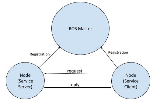
What is a ROS Service? A ROS Service consists of a pair of messages: one for the request and one for the reply. A service-providing ROS node (i.e. Service Server) offers a service (e.g. read sensor data).
A client node (i.e. Service Client) calls the service by sending a request message to the service provider. The client node then awaits the reply.
Here is what the ROS Service model looks like:
In ROS, a service is defined using .srv files.
Let’s create a service now. We need to create a service server and a service client. In this example, the service server provides the service of adding two numbers together. A service client calls this service by sending the server the two numbers it wants to add. The response from the service server will be the sum of those two numbers.
Open a new terminal window, and go to the noetic_basics_part_1 package.
roscd noetic_basics_part_1
Create a folder named srv.
mkdir srv
See if the folder was created.
dir

Now move into that folder.
cd srv
Inside the srv folder, create a file named noetic_basics_part_1_srv.srv.
gedit noetic_basics_part_1_srv.srv
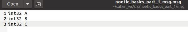
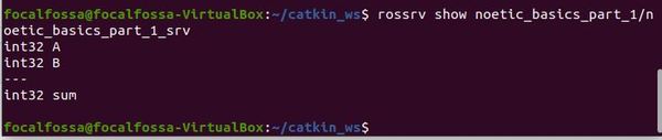
Add the following lines to the file. int32 A and int32 B are the two data types and values that the service client will provide to the service provider.
int32 sum will be the response from the service provider (i.e. the sum of the signed 32-bit integers A and B).
int32 A
int32 B
---
int32 sum
Click Save and close the text editor.
Now go back up one directory.
cd ..
Open the package.xml file. The package.xml file defines the properties of a package like package name, version number, author, maintainer, dependencies on other packages, etc.
gedit package.xml
Make sure these two lines are uncommented.
<build_depend>message_generation</build_depend>
<exec_depend>message_runtime</exec_depend>
Save the package.xml file and close it.
Now open the CMakeLists.txt file. Remember this file contains instructions on how to build the code inside the package.
gedit CMakeLists.txt
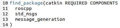
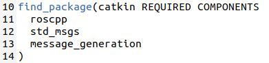
Make sure you put message_generation into the find_package scope.
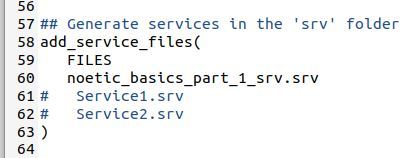
Now uncomment the add_service_file lines.
Add the name of the new .srv file you created.
noetic_basics_part_1_srv.srv
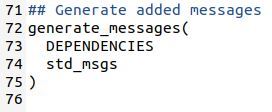
Now make sure these lines are uncommented.
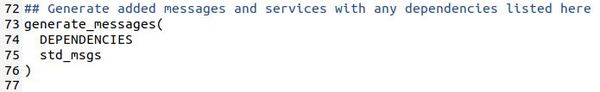
Save the CMakeLists.txt file and close it to return to the terminal window.
Let’s build the package to make sure all the changes we’ve made are incorporated.
cd ~/catkin_ws/
catkin_make
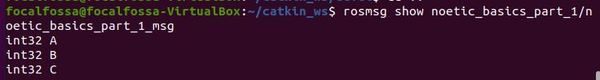
Let’s see if everything was built properly.
rossrv show noetic_basics_part_1/noetic_basics_part_1_srv
Now that we have created the service data type, we need to create two nodes: a service server and a service client.
We will create two files:
- simple_service_server.cpp
- simple_service_client.cpp
Open up a new terminal window.
Move to the src folder of the package we created earlier called noetic_basics_part_1.
roscd noetic_basics_part_1/src
Let’s create a C++ program named simple_service_server.cpp.
Type this command to open a brand new C++ file.
gedit simple_service_server.cpp
Type the code below into the file.
/**
 * A basic program for a Service Server in ROS
 * @author Addison Sears-Collins (https://automaticaddison.com/)
 * @version 1.0
 */

// Include the header file that has declarations for the standard ROS classes
#include "ros/ros.h"

// Include the srv file that we already created
#include "noetic_basics_part_1/noetic_basics_part_1_srv.h"

// Add two numbers and output the sum
bool add(noetic_basics_part_1::noetic_basics_part_1_srv::Request  &req,
         noetic_basics_part_1::noetic_basics_part_1_srv::Response &res) {
  res.sum = req.A + req.B;
  ROS_INFO("Request: A=%d, B=%d", (int)req.A, (int)req.B);
  ROS_INFO("Response: [%d]", (int)res.sum);
  return true;
}

// Main ROS method
int main(int argc, char **argv) {

  // Initialize the node and set the name
  ros::init(argc, argv, "adder_server");

  // Create the main access point for the node
  // This piece of code enables the node to communicate with the ROS system.
  ros::NodeHandle n;

  // Create the service and advertise it to the ROS computational network
  ros::ServiceServer service = n.advertiseService("noetic_basics_part_1/adder", add);

  // Print message to terminal window
  ROS_INFO("adder_server has started");

  // Keep processing information over and over again
  ros::spin();

  // Program completed successfully
  return 0;
}
Click Save and close the editor.
Now type this command to open a brand new C++ file.
gedit simple_service_client.cpp
/**
 * A basic program for a Service Client in ROS
 * @author Addison Sears-Collins (https://automaticaddison.com/)
 * @version 1.0
 */

#include "ros/ros.h"
#include "noetic_basics_part_1/noetic_basics_part_1_srv.h"

// This header is for the C standard general utilities library
// It defines some general purpose functions such as integer arithmetic
#include <cstdlib>

int main(int argc, char **argv) {

  // Initialize the node and set the name
  ros::init(argc, argv, "adder_client");

  // argc is the count of the number of arguments passed in the command line
  // For example, if you're adding two numbers, the three arguments in the
  // Linux terminal would be the stuff in between []:
  //   rosrun <package_name> [client_name] [1st_number] [2nd_number]
  // This code below checks that there are three arguments passed in the command
  // line. If there aren't a message is printed to the terminal window.
  if (argc != 3) {
    ROS_INFO("Usage: adder_client A B ");
    return 1;
  }

  // Create the main access point for the node
  // This piece of code enables the node to communicate with the ROS system.
  ros::NodeHandle n;

  // Create a client for the service named noetic_basics_part_1/adder
  ros::ServiceClient client = n.serviceClient<noetic_basics_part_1::noetic_basics_part_1_srv>("noetic_basics_part_1/adder");

  // Create an instance of the srv request type
  noetic_basics_part_1::noetic_basics_part_1_srv srv;

  // Fill in the two values that will be sent to the Service Server
  srv.request.A = atoll(argv[1]);
  srv.request.B = atoll(argv[2]);

  // Call the service, and send the data
  if (client.call(srv))
  {
    ROS_INFO("Sum: %ld", (long int)srv.response.sum);
  }
  else
  {
    ROS_ERROR("Failed to call service adder_server");
    return 1;
  }

  return 0;
}
Click Save and close the editor.
Let’s edit the CMakeLists.txt file for the noetic_basics_part_1 package. Open a new terminal window, and type this command:
roscd noetic_basics_part_1
gedit CMakeLists.txt
Now add these lines to the bottom of the CMakeLists.txt file:
add_executable(simple_service_server src/simple_service_server.cpp)
target_link_libraries(simple_service_server ${catkin_LIBRARIES})

add_executable(simple_service_client src/simple_service_client.cpp)
target_link_libraries(simple_service_client ${catkin_LIBRARIES})
Click Save and close the text editor.
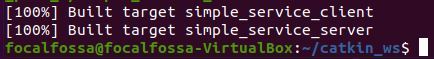
Open a new terminal window, and type the following commands to build all the nodes in the noetic_basics_part_1 package:
cd ~/catkin_ws
catkin_make
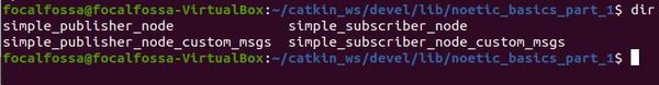
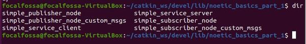
Now, open a new terminal window and go to the catkin_ws/devel/lib/noetic_basics_part_1/ folder.
cd ~/catkin_ws/devel/lib/noetic_basics_part_1/
Type dir to see the files listed. You will see the new executables we just created. Feel free to close the terminal window now.
Ok, now that we have built our nodes, let’s run them.
Open up a new terminal window and launch the ROS Master.
roscore
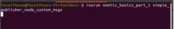
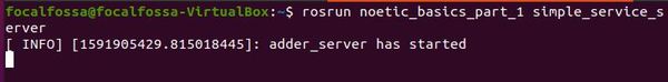
In a new terminal tab, type the following command to run the publisher node:
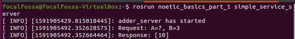
rosrun noetic_basics_part_1 simple_service_server
Here is the output. You should see a message that says “adder_server has started”.
Now, let’s run the subscriber node. Type the following command in a new terminal tab to add the numbers 7 and 3.
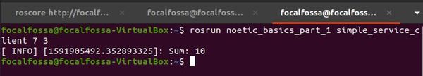
rosrun noetic_basics_part_1 simple_service_client 7 3
Here is the output of the service client window. You should see “Sum : 10”:
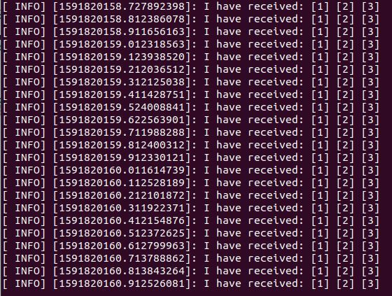
Here is the output of the service server window.
When you’re done, press Ctrl + C in all open terminal windows.