
In this post, I’ll show you how to wire the batteries and motors of a basic wheeled robot.
Shout out to the late Gordon McComb for this project idea. He is the author of an excellent book that I recommend buying if you’re getting started with robotics: How to Make a Robot.
Requirements
Here are the requirements:
- Connect the left servo, right servo, and AA batteries to the solderless breadboard.
You Will Need
The following components are used in this project. You will need:
- Continuous Rotation Servo Motor
- Arduino/Elegoo Uno (Mine is in a protective case, which is optional)
- 9V Battery
- 9V Barrel Jack Connector
- 4xAA Battery Holder
- 4 AA Batteries
- Solderless Breadboard (400 Point)
- Male-to-Male Jumper Wire
- Wire Strippers
Directions
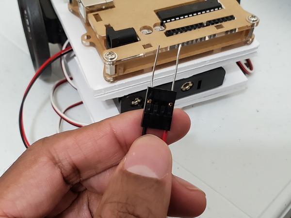
Take off all of the insulation from a 6-inch long male-to male jumper wire.
Cut the jumper wire into eight pieces that are each 0.5 inches in length.
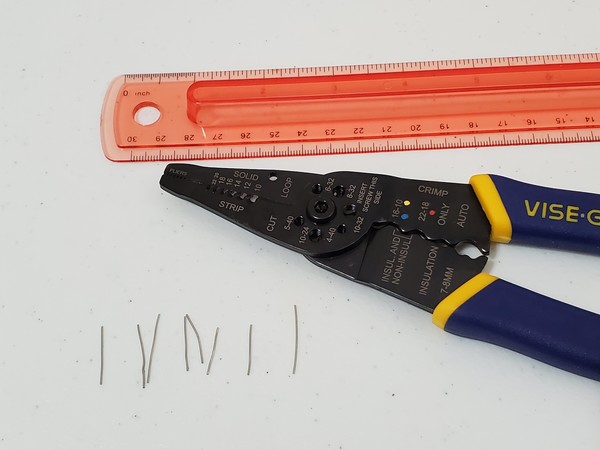
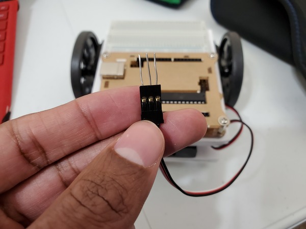
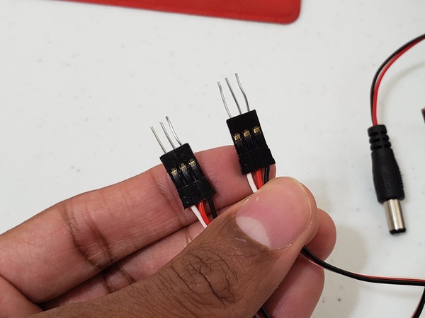
Use pliers or the end of your wire stripper to push the jumper wire pieces into the connectors of the two servos and the 4 x AA battery holder.
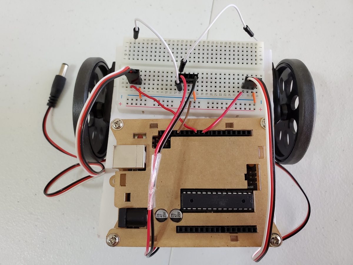
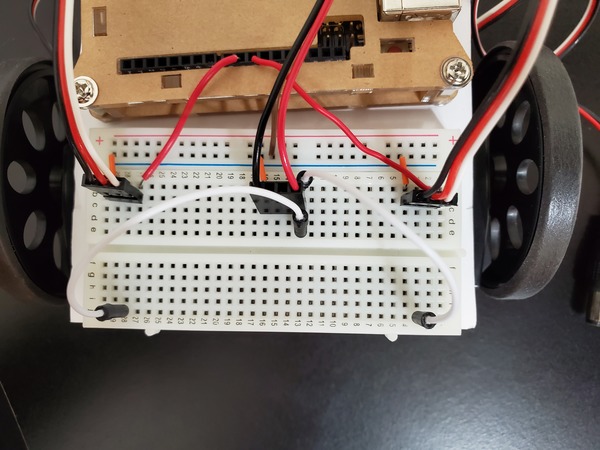
Connect the black lead of the left servo to cell b4 of the solderless breadboard.
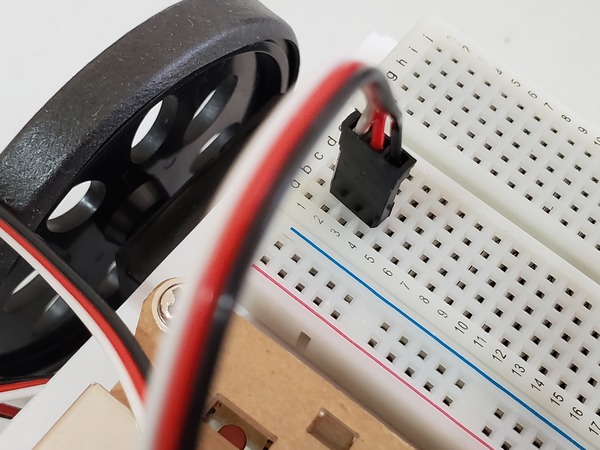
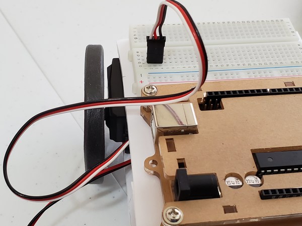
Connect the black lead of the right servo to cell b29 of the solderless breadboard.
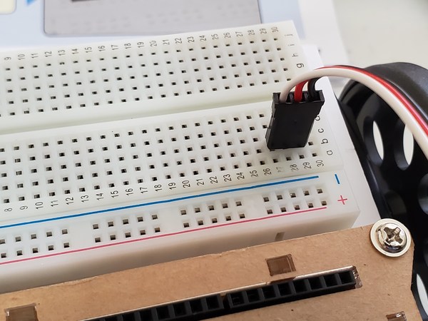
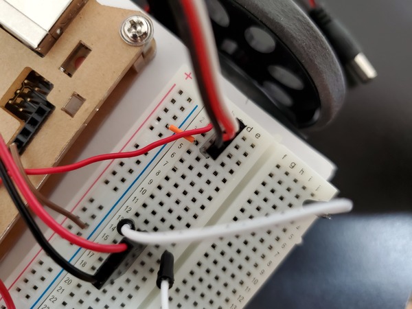
Connect cell a4, a16, and a29 to the blue (-) negative rail of the solderless breadboard using a jumper wire.
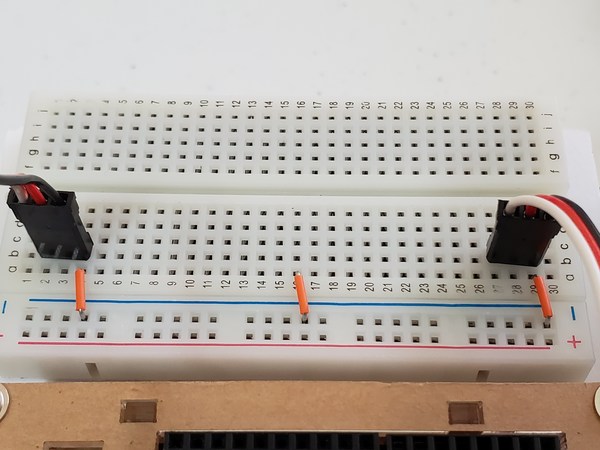
Connect the black lead of the 4 x AA battery connector to cell b16. The red lead should sink down in b13.
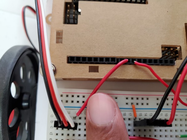
Connect the Digital 10 pin of the Arduino to cell a2 of the breadboard.
Connect the Digital 9 pin of the Arduino to cell a27 of the breadboard.
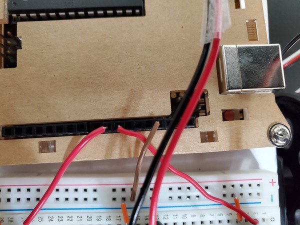
Connect the Ground (GND) pin of the Arduino to the blue negative rail of the breadboard (brown jumper wire in the image below).

Connect a jumper wire from cell a13 to j3 (or any cell on the other side of the groove of the breadboard). This wire provides power (i.e. turned ON) to the left servo when it is connected from cell a13 to cell e3. When it is connected from cell a13 to j2, the left servo is turned OFF.
- a13 to e3 = left servo ON
- a13 to j2 = left servo OFF
Connect a jumper wire from cell e13 to j28 (or any empty cell on the other side of the groove of the breadboard, excluding row 2). This wire provides power (i.e. turned ON) to the right servo when it is connected from cell e13 to cell e28. When it is connected from cell e13 to j28, the right servo is turned OFF.
- e13 to e28 = right servo ON
- e13 to j28 = right servo OFF
That’s it for the wiring. In the next post, we will create a program on Arduino that enables the robot to make basic movements autonomously.