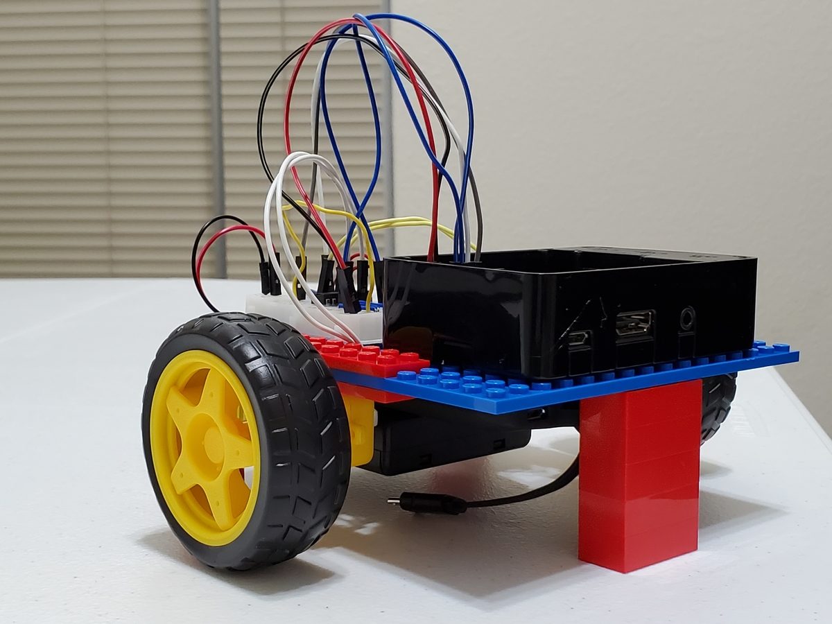
In this post, I will show you how to make a wheeled robot using Raspberry Pi as the “brain” of the robot.
Special shout out to Matt Timmons-Brown for this project idea. He is the author of a really good book on Raspberry Pi robotics: (Learn Robotics with Raspberry Pi). Go check it out!
Requirements
Here are the requirements:
- Make a wheeled robot using Raspberry Pi as the “brain” of the robot.
You Will Need
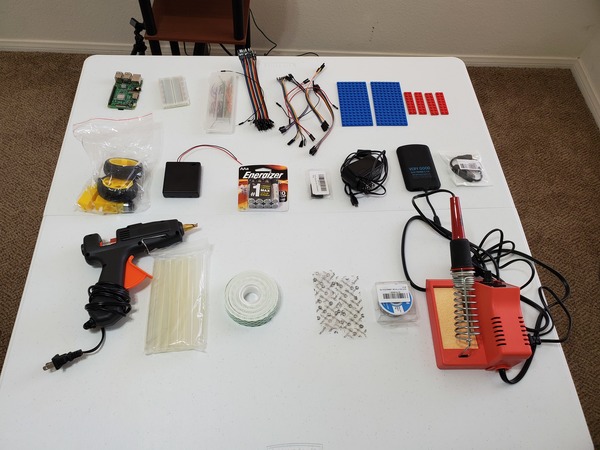
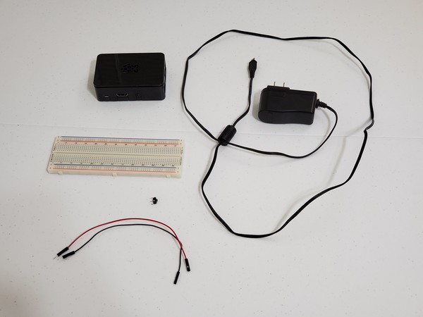
The following components are used in this project. You will need:
- CanaKit Raspberry Pi 3 Complete Starter Kit
- Raspberry Pi 3 Protective Case (optional)
- 400-point Solderless Breadboard (for connecting Raspberry Pi to motors and other components)
- Male-to-male Jumper Wires (for connecting components)
- Female-to-male Jumper Wires (for connecting components)
- Two 8×16 Lego Plates (8 dots x 16 dots) for the robot body (available from eBay)
- Four 2×8 Lego Plates (2 dots x 8 dots) for the robot body (available from eBay)
- Two Robot Tires with 3-6 V DC Gear Motor (available from ebay)
- 4xAA Battery Holder 6V with On/Off Switch (powers the two motors)
- Four AA Batteries (powers the two motors)
- Dual H-Bridge Motor Driver (L293D) for DC or Steppers (I bought Adafruit Part 807)
- Contains two H-bridges. An H-bridge is a circuit that enables a motor to go both forwards AND backwards.
- Power for the Raspberry Pi (requires 5V supply in order to run)
- Option 1 (Recommended, this is what I’ll use):
- Option 2 (More complicated):
- LM2596 DC Step Down Converter Voltage Regulator
- 9V Batteries
- 9V Battery Battery Clip with Leads
- Multimeter
- 60W/100W Dual Power Hot Glue Gun with Glue Sticks
- Scotch Permanent Mounting Tape, 1 Inch
- VELCRO Brand – Thin Clear Fasteners 7/8 in Squares
- Scotch Permanent Mounting Tape
- Black Electrical Tape
- 40-Watt Soldering Station
- 63-37 Tin Lead Rosin Core Solder
- Wire Strippers (I use the IRWIN VISE-GRIP brand)
Directions
Building the Robot’s “Body”
Let’s start by building the body of the robot.
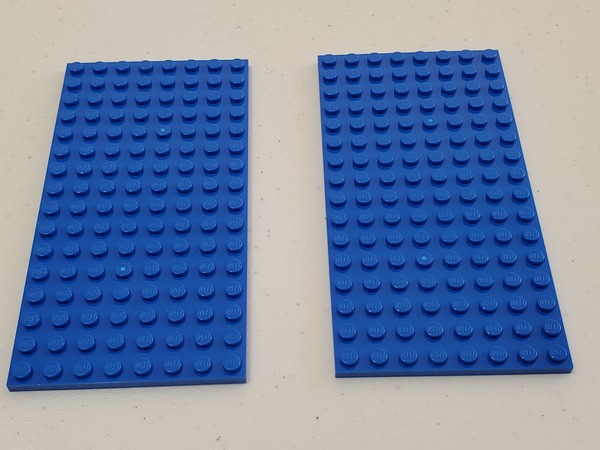
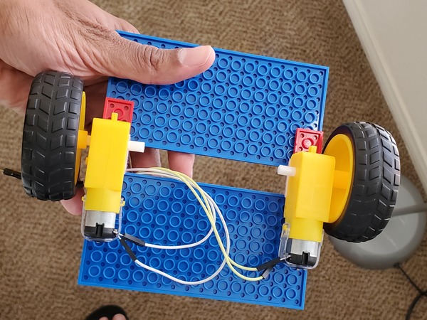
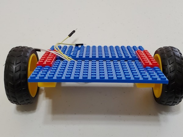
Grab the two 8×16 Lego plates, and place them apart from each other.
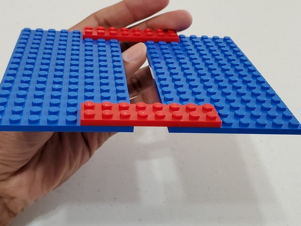
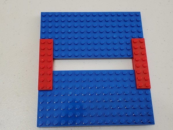
Connect the two 8×16 Lego plates with the two 2×8 Lego plates. Place them across to form a bridge.
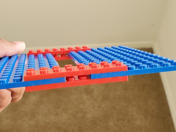
Connect the other two 2×8 Lego plates to the underside of the 8×16 Lego plates to form a sandwich.
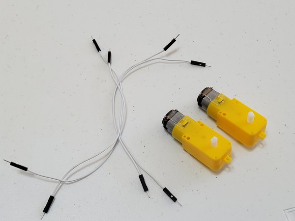
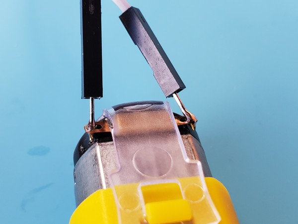
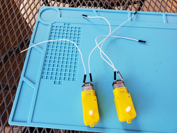
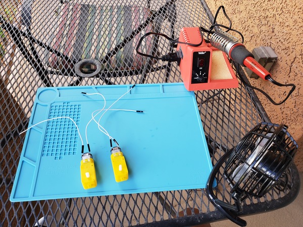
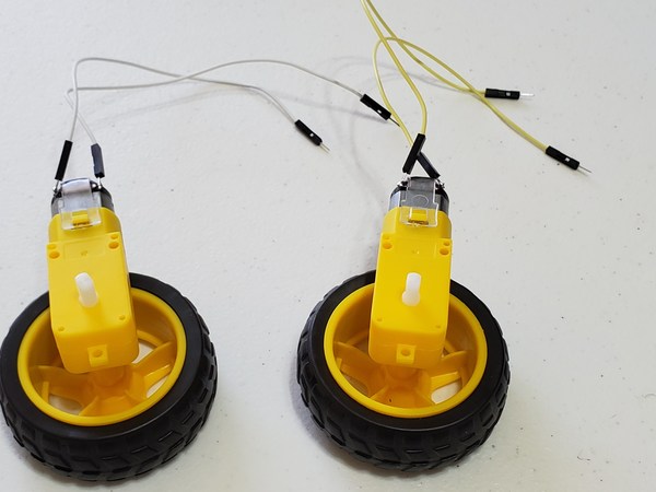
Solder male-to-male wires to both terminals of each motor (they might already be soldered). If you need a quick tutorial on how to solder, check out this video, or just Google “How to Solder”:
Pop the tires on to the white rod on both motors. Give it a strong push in there. The wheels should be on the other side of the motor terminals.
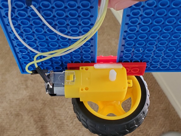
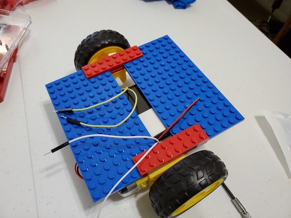
Stick the motor wires up through the gap in the robot body.
Mount the motors with tire to the underside of the robot’s body so that the tires are exactly in the middle of the body. Make sure the tires are exactly parallel to each other.
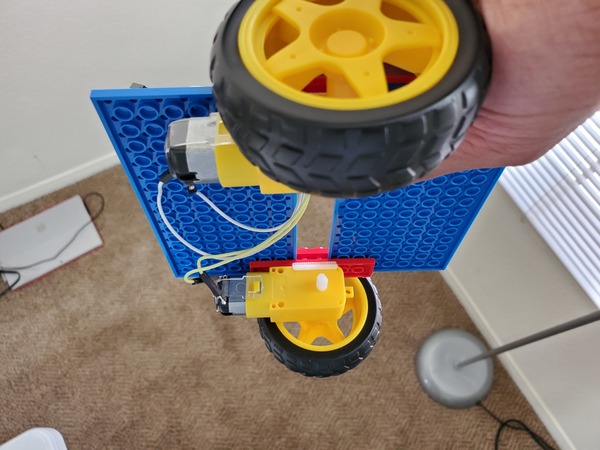
Secure the motors to the body of the robot using your hot glue gun (100W setting). If you don’t want the motors to be permanently stuck to the robot’s body, you can use Velcro or Scotch permanent mounting tape.
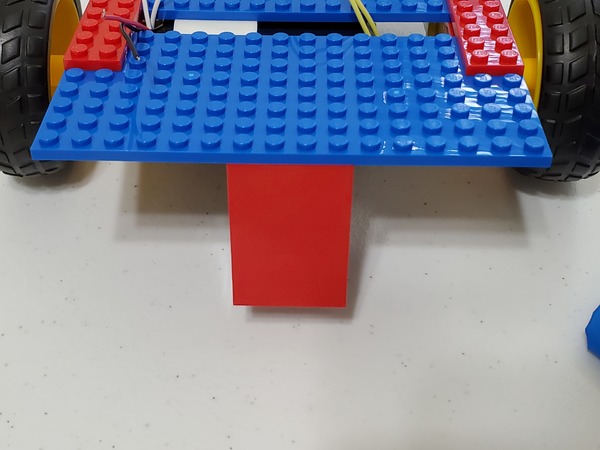
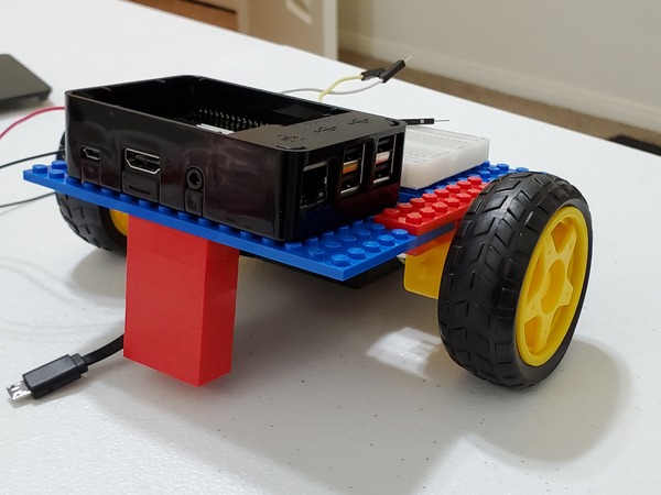
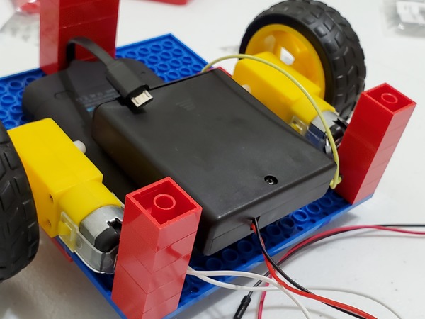
Stabilize the robot by adding five 2×4 Lego bricks to both the front of the body.
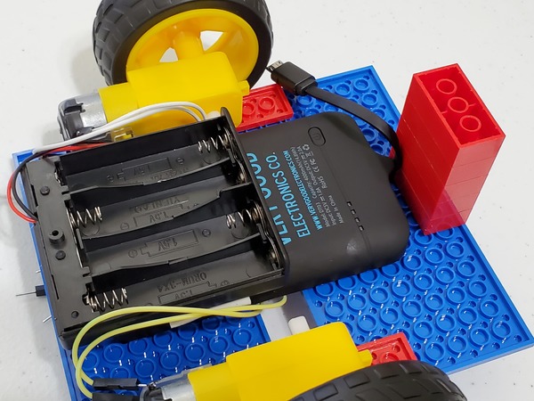
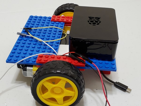
Mount the Raspberry Pi battery pack to the underside of the robot, slightly off-center of the body, using Velcro or Scotch permanent mounting tape. The small cable of the battery pack should face the front of the car.
Mount the 4xAA battery holder to the battery pack. Use Velcro or Scotch permanent mounting tape to secure it into place. Make sure that you are still able to reach the ON/OFF switch of the 4xAA battery pack.
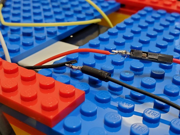
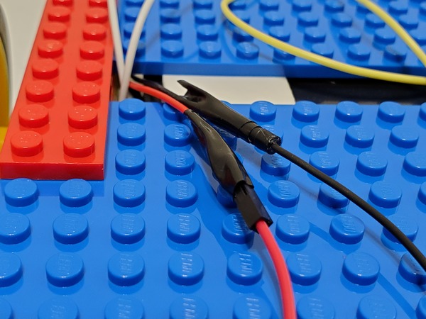
Feed the negative (black) and positive (red) leads through the gap in the robot body.
Strip 1-2 cm of insulation off the end of the battery pack wires using the wire strippers.
Wrap the red and black wires of the battery pack around male-to-male jumper wires.
Solder the wires together so that they remain in place.
Apply black electrical tape around the connection once it has cooled.
Giving the Robot a “Brain” by Adding the Raspberry Pi
Our robot needs to have a brain. Otherwise, it is just a bunch of plastic parts that can’t do anything useful. In this project, we’ll use the Raspberry Pi as the robot’s brain.
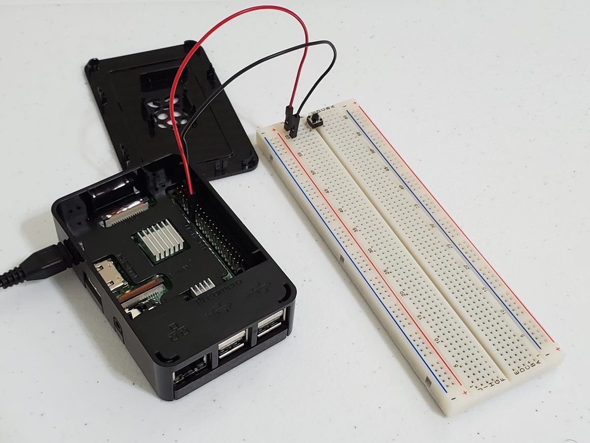
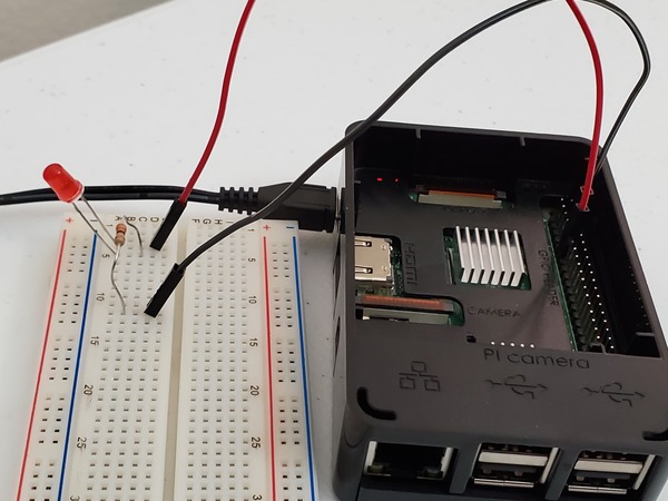
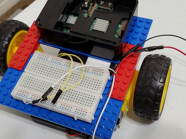
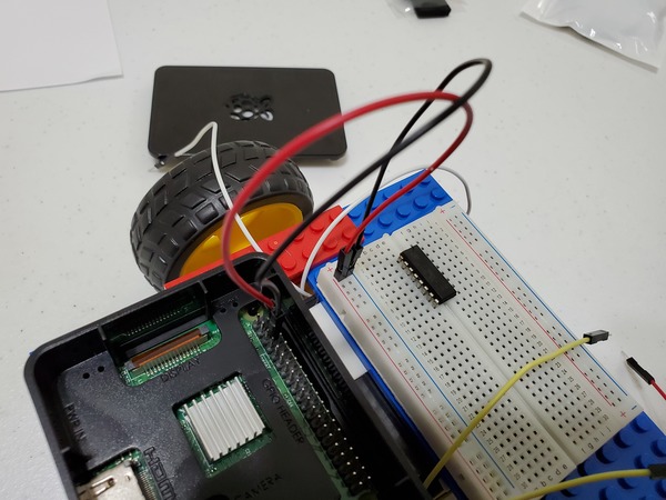
Grab some Velcro and stick the Raspberry Pi on top of the front end of the robot’s body. Make sure it looks exactly like the image below.
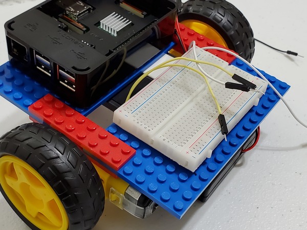
Grab some Velcro and stick the 400-point solderless breadboard on the back end of the robot, opposite to where the Raspberry Pi is located. You could also peel off the back of the sticker on the solderless breadboard.
Giving the Robot a “Nervous System”
Now that the robot has a brain (Raspberry Pi mounted on the front of the robot) and a body, it needs a “nervous system,” communication lines that enable the brain to transmit signals to and from different parts of its body. In the context of this project, those communication lines are the wires that we need to connect between the different parts of the robot we’re building.
Setting up the Breadboard
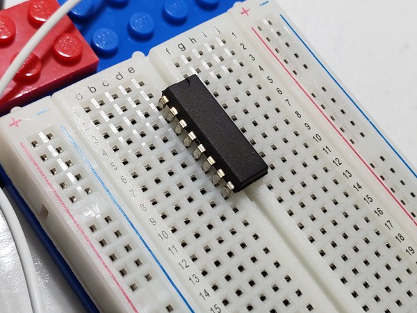
Sink the 16 pins of the L293D motor controller down into the holes of the solderless breadboard so that the controller straddles the gap that runs the length of the breadboard.
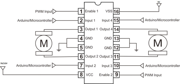
Here is the diagram of the L293D.
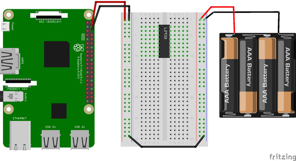
Put pin 1 (the pin just to the left of the half-circle notch in the L293D into pin e3 of the solderless breadboard. You’ll have to bend the legs a bit of the L293D to get it to sink down. Note: Ignore the AAA on the batteries below. They are actually AA.
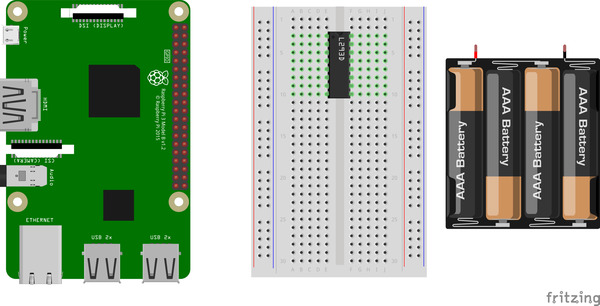
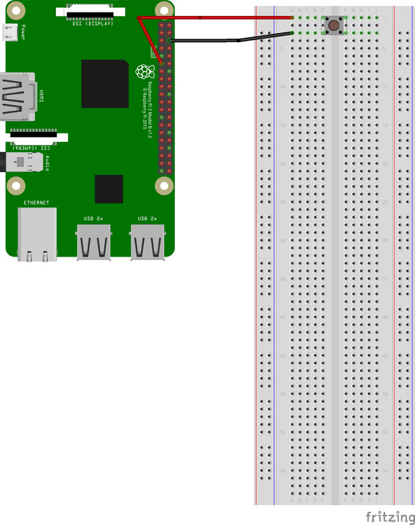
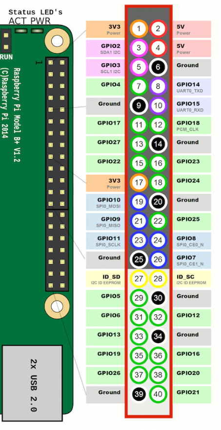
Here is the pin diagram of the Raspberry Pi.
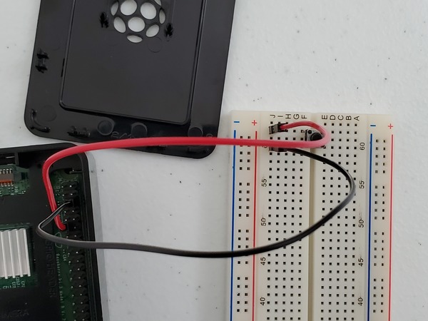
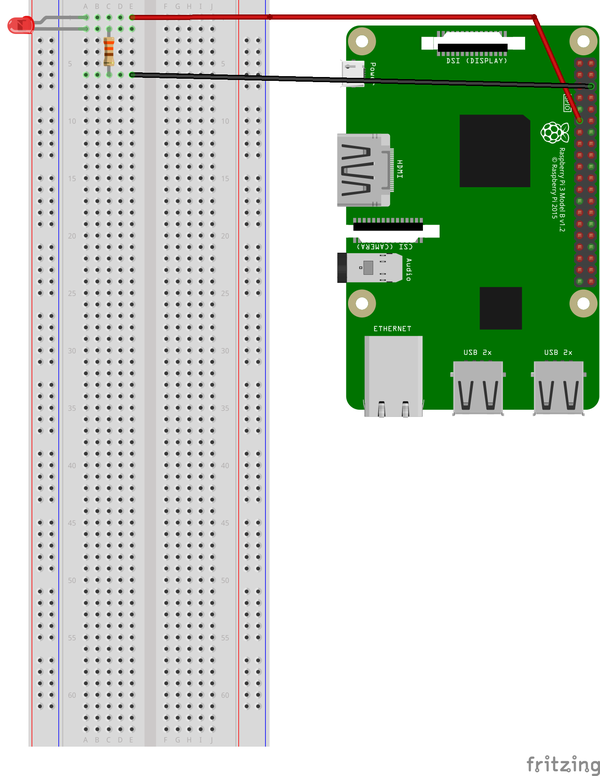
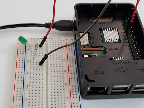
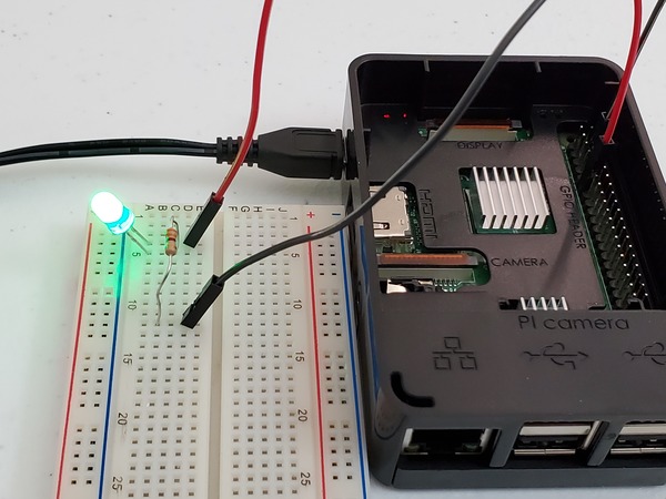
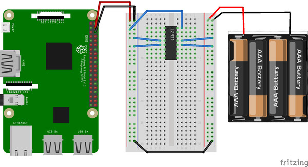
Power up one set of positive/negative rails of the solderless breadboard:
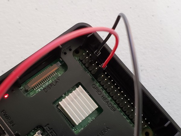
- 5V pin (pin 4) of the Raspberry Pi connects to the red (positive) power rail of the breadboard using a male-to-female jumper wire.
- Connect the Ground pin (pin 6) of the Raspberry Pi to the blue (negative) power rail of the solderless breadboard.
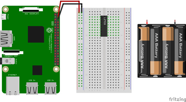
Power up the other set of positive/negative rails of the solderless breadboard:
- Connect the blue (negative) power rail to the other blue (negative) power rail using a male-to-male jumper wire.
- Put the red positive lead of the 4xAA battery holder into a hole on the unused red (positive) rail of the solderless breadboard.
- Put the black lead of the 4xAA battery holder into the blue (negative) rail of the solderless breadboard.
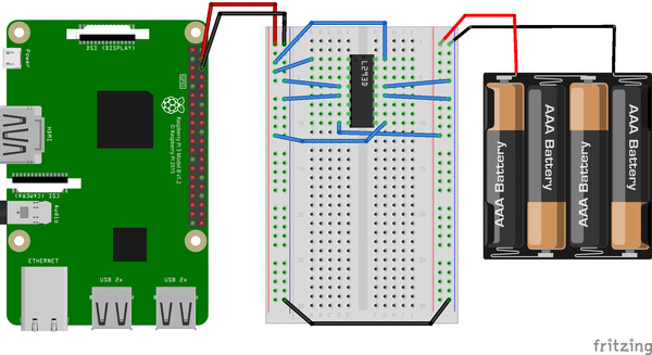
Connecting the 16 Pins of the L293D
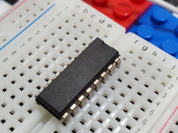
Here is the diagram of the L293D motor controller.

The L293D motor controller needs a power supply:
- Connect pin 16 (vss 1) to the 5V red (positive) power rail of the solderless breadboard, the rail that is powered by the Raspberry Pi. This pin is the one that will provide power to the L293D motor controller. You can stick a male-to-male pin in g3 of the solderless breadboard and connect that to the red rail.
- Connect all the GND pins of the L293D (pins 4, 5, 12, and 13) to the closest blue (ground) power rail of the solderless breadboard.
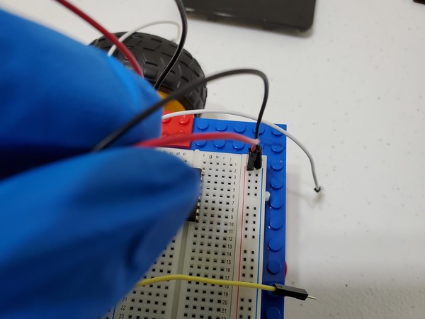
The motors need a power supply:
- Connect a male-to-male wire from the red 6V power rail (the rail connected to the 4xAA battery pack) to pin 8 (vcc) of the L293D integrated chip.

In order for the motors to accept commands from the Raspberry Pi, we need to connect both enable pins (pins 1 and 9) of the L293D to red (positive) 5V power rails. Here are the steps:
- Take a male-to-male jumper wire and make a connection between pin 1 of the L293D and the the red (positive) rail of the breadboard (the one connected to the 5V pin of the Raspberry Pi).
- Take a male-to-male jumper wire and make a connection between pin 9 of the L293D and the the red (positive) rail of the breadboard (the one connected to the 5V pin of the Raspberry Pi).
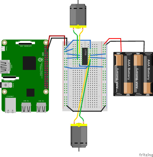
We need to connect the motors to the output pins of the L293D.
- Motor 1 (Right Motor)
- Connect one of the leads to Output 1 (pin 3) of the L293D.
- Connect the other lead to Output 2 (pin 6).
- Motor 2 (Left Motor)
- Connect one of the leads to Output 3 (pin 11) of the L293D.
- Connect the other lead to Output 4 (pin 14).
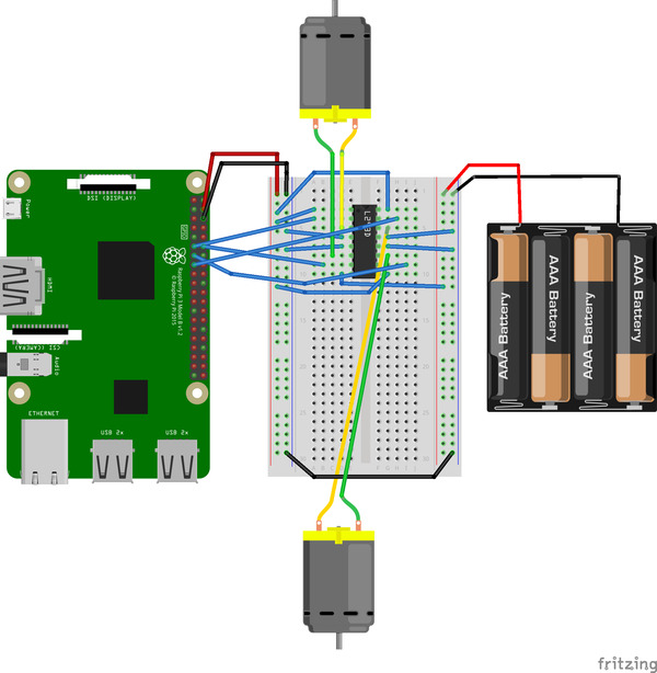
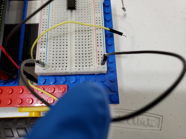
Now, we need to connect the input pins of the L293D to the Raspberry Pi. There are two input pins for each motor.
- Connect Pin 11 (GPIO 17) of the Raspberry Pi to pin 2 (Input 1) of the L293D.
- Connect Pin 12 (GPIO 18) of the Raspberry Pi to pin 7 (Input 2) of the L293D.
- Connect Pin 13 (GPIO 27) of the Raspberry Pi to pin 10 (Input 3) of the L293D.
- Connect Pin 15 (GPIO 22) of the Raspberry Pi to Pin 15 (Input 4) of the L293D.
Insert fresh AA batteries into the 4xAA battery holder.
Whew! That was a lot of work. If you made it this far, congratulations! You have completed construction of your Raspberry Pi wheeled robot.
In order for it to do something useful (e.g. move from one place to another), we need to program its brain, the Raspberry Pi. We will tackle this in the next post.